FCI FS10A Installation & Operation Manual
Analyzer flow switch/monitor
Hide thumbs
Also See for FS10A:
- Installation & operation manual (56 pages) ,
- Installation & operation manual (78 pages)

Related Manuals for FCI FS10A


Summary of Contents for FCI FS10A
- Page 1 Models FS10A, FS10i Analyzer Flow Switch / Monitor Fluid Components International LLC (FCI). All rights reserved.
- Page 2 Any other use is strictly prohibited without the prior written consent of FCI. © Copyright 2018 by Fluid Components International LLC. All rights reserved. FCI is a registered trademark of Fluid Components International LLC. Information subject to change without notice.
-
Page 3: Table Of Contents
FS10 Series 06EN003394 Rev. K Table of Contents TECHNICAL SPECIFICATIONS ..................................1 1 INSTRUMENT DESCRIPTION AND IDENTIFICATION .........................2 2 INSTRUMENT INSTALLATION ................................2 Special Conditions for Safe Use.......................................2 Remote Flow Element Installation Into Zone 1, Division 1 Areas ...........................2 Mounting Orientation ........................................3 3 INSTRUMENT WIRING .....................................4 Recommended Minimum Wire Gauge ....................................4 Grounding ............................................4... - Page 4 06EN003394 Rev. K FS10 Series Preferred Method: Level Can Be Adjusted During Setup ............................28 Probe Normally Wet, Level Cannot Be Adjusted During Setup ..........................28 Probe Normally Dry, Level Cannot Be Adjusted During Setup ...........................28 Output and Display Parameters......................................29 PC Interface and Command Line Interface Configurations ............................31 FS10 Communication Options .....................................31 Windows PC Interface Software ....................................32 Flow Rate Indication on PC Interface ..................................32...
-
Page 5: Technical Specifications
ƒ Process Connection Standard: -40 °F to 250 °F [-40 °C to 121 °C] FS10A: ¼" NPT; compatible with ¼", 3/8" and ½" tube tee, FS10i, Teflon ferrule: -40 °F to 200 °F [-40 °C to 93 °C] ¼" tube tee with 1/8" injection tube adapters and SP76 adapter (FCI Electronics limited to 160 °F [71 °C]... -
Page 6: Instrument Description And Identification
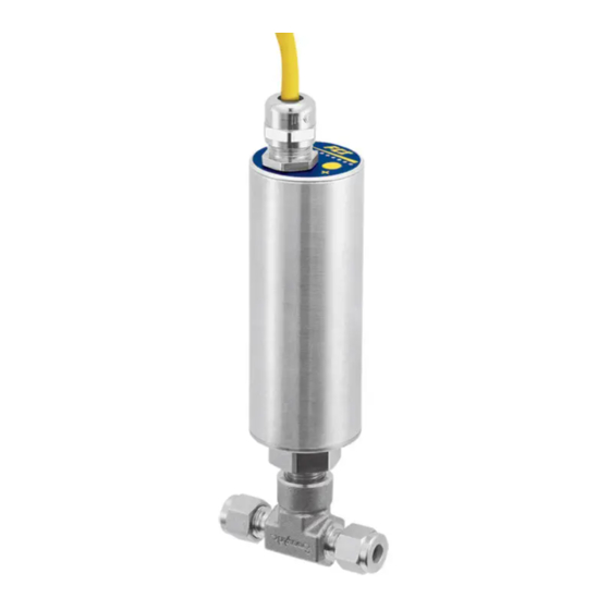
INSTRUMENT DESCRIPTION AND IDENTIFICATION The FS10 Series is a universal flow monitor and switch specifically designed for gas and liquid process analyzer sampling systems. The FS10A is a fast re- sponding, highly repeatable sensor which installs easily into a standard tube tee fitting or SP76 (NeSSI) modular manifold. The FS10i is an insertion type instrument with ¼-inch or ½-inch NPT fitting (fixed 2- or 4-inch length) or ½-inch NPT compression fitting (6-inch length, Teflon or stainless steel ferrule). -
Page 7: Mounting Orientation
FS10 Series Mounting Orientation Left to Right Flow Example in 1/4 and 3/8 inch tube tees For optimum sensitivity in low flow applications, install probes with the “A” (Active) sensor positioned upstream. Horizontal lines: gas or liquid. “A” (Active) mark Vertical lines: gas - flow must be down Upstream... -
Page 8: Instrument Wiring
Input Power, 24 VDC FCI recommends installing an input power disconnect and a fuse near the instrument to interrupt power during installation, maintenance, calibration, alarm selection and troubleshooting procedures. Install conduit according to the local electrical codes or hazardous location requirements. - Page 9 FS10 Series Caution: Instrument power is provided to Pin 1 of the I/O connector/cable (white wire). To avoid equipment damage always be sure that power is connected to Pin 1 (white wire) when making external I/O cable connections. Do NOT apply power to Pin 8 (red wire) or any other pin other than Pin 1.
- Page 10 FLOW ELEMENT CIRCUIT BOARD FROM FLOW ELEMENT WITH POTTED CABLE (2) CONNECTORS 8-WIRE SHIELDED CUT JUMPERS J3 TERMINAL STRIP (FCI 021487-02 CABLE (J4 & J5) SIGNAL NAME/PIN NUMBER PIN NUMBER (LOW/MED TEMP) ACT DRIVE + ACT SENSE + ACT SENSE - ACT &...
- Page 11 FS10 Series (OEM) Fluid Components International LLC...
-
Page 12: Fs10 Output Modes
Switching Inductive Loads If the FS10A/FS10i relay contacts are to be used to energize or de-energize an external relay, diode suppression must be used across the external relay coil. Use the guidelines in the following example to select the proper diode. -
Page 13: Fs10 Outline Installation Drawing
FS10 Series FS10 Outline Installation Drawing Fluid Components International LLC... -
Page 14: Fs10 1/4-Inch Tube Tee Assy With 1/8" Tube Adapters And Injection Tubes
12 = REDUCER SUB-ASSY ONLY, .063 I.D. 94 = PAIR (2) OF REDUCER SUB-ASSY .094 I.D. 63 = PAIR (2) OF REDUCER SUB-ASSY .063 I.D. 4. PRESSURE RATING, PER MAX. ALLOWED FS10A. OPTIONAL TEE REPLACEMENT FOR HAMLET TEE AVAILABLE ON REQUEST. -
Page 15: Fs10 Flow Element Options
FM: 3022666 PLUS FM: 302266 PLUS FM: 302346 PLUS FM: 3023468 PLUS 500° RATED ELEMENT8 500° RATED ELEMENT 500° RATED ELEMENT 500° RATED ELEMENT6 FCI PN 020800 FCI PN 020000 FCI PN 021145 FCI PN 019348 ALL-WELDED ALL-WELDED PRESS-FIT PRESS-FIT 1/2"... -
Page 16: Fs10 Remote Enclosure And Connection Options
FS10 Series FS10 Remote Enclosure and Connection Options PANEL MTG. RING BRACKET, Boot and hex plug removed OPTIONAL (incl. in kit 025719-01) to show RS-232 connection RS-232 2.5 mm TRS (STEREO) PHONE JACK (under hex plug) Ø2.25 , OD Ø 1.50, ENCLOSURE (NO BOOT) Ø... -
Page 17: Fs10I Top Assembly
FS10i Top Assembly Note: An FS10i housing is secured with removable screws. The original FS10A housing was secured with fixed pins that were not removable in the field. Later versions of the FS10A are supplied with removable housing screws. The disassembly instruc- tions below apply to any FS10 unit with removable housing screws. -
Page 18: Sensor Subassembly
FS10 Series Sensor Subassembly Remove only to change jumper selection on board per diagram. Remove screws to reclock BOOT REMOVED FOR probe orientation 90° or 180°. CLARITY Apply Loctite Blue to screw threads before reinstalling. CAUTION: Unit is supplied with sufficient wire slack to rotate probe 180°... -
Page 19: Dimensional Outlines
FS10 Series Dimensional Outlines Fluid Components International LLC... - Page 20 FS10 Series Fluid Components International LLC...
-
Page 21: Installation Dimensions, Fs10 Remote Panel Mounting Ring Kit (025719-01)
FS10 Series Installation Dimensions, FS10 Remote Panel Mounting Ring Kit (025719-01) 4x SET SCREW, SST 18-8, 4-40 x .25 RING BRACKET, REMOTE END 2x SCREW, 18-8 SST CAP, FS10 #8-32 UNC X 3/8 IN. CONFIGURATION SHOWN: (4.19) 025717-40002E00X12 [106.4] (.13) [3.3] (1.13) [28.7]... -
Page 22: Installation Dimensions, Fs10 Remote Mounting Bracket (025442-01)
FS10 Series Installation Dimensions, FS10 Remote Mounting Bracket (025442-01) (Ø1 . 50) [38.1] MOUNTING BRACKET (025442-01) 5.44 [138.1] (.98) [24.9] USE #8 or [M4] SECURING SCREW, LENGTH AS APPROPRIATE FOR MOUNTING SURFACE 1.66 (Ø .18) [42.1] [4.5] (Ø1 .69) [42.9] (.90) [22.8] (1.79) -
Page 23: Installation Details, Fs10 Silicone Boot And Uv Filter
FS10 Series Installation Details, FS10 Silicone Boot and UV Filter SILICONE BOOT, PULL OFF/PUSH ON (P/N 025529-01) UV FILTER DISC (P/N 026125-01A) BUTTONS (2x) (Remove UV filter disc first before actuating buttons.) INSTRUMENT BODY C01437-1-1 Fluid Components International LLC... - Page 24 FS10 Series Intentionally Left Blank Fluid Components International LLC...
-
Page 25: Power Up, Functional Verification And Adjustment
FS10 Series POWER UP, FUNCTIONAL VERIFICATION AND ADJUSTMENT Before applying power to the instrument, it is recommended that a third party inspect the installation workmanship. Make sure wires are not pinched or frayed. Check for matching serial numbers on the sensing element and the control circuit. Verify that the power and alarm circuits are properly connected. -
Page 26: Fs10 Field Quick Setup Procedure
FS10 Series FS10 Field Quick Setup Procedure Select desired setup option A or B below by pressing the (-) or (+) button continuously for the designated time period. In either case, the ability to set up the device in actual flow conditions is required, i.e., actual switch point flow rate, or flow close to intended value (Mode A) or actual zero flow and full scale flow (Mode B). -
Page 27: Quick Setup Mode Summary
FS10 Series Table 4 – Quick Setup Mode Defaults Button Selection (Default Settings Parameter (–) Initial Button Press: Enter Function Mode (A or B) Bank Selection Fail-safe High Hysteresis Relative to Above Below Switch Point Common to Mode A and Mode B NAMUR High Relay Trip Adjust - Step... - Page 28 FS10 Series Mode B: Capture Zero and Span + Set Default Switch Point If Mode A is not selected (button not released), after 10 seconds LED pattern changes to LEDs sequencing down from 3 to 1 and LEDs 8 to 10 sequencing up, indicating Mode B. Release button to enter into this setup option. The FS10 is now cued to remember the low- est and highest flow signal it sees while in this mode.
-
Page 29: Fs10 Button Controls - Alternate Setup Method
FS10 Series Note: If using the 4-20 mA output, create a zero offset to significantly improve the linearization of that output; i.e., instead of scaling between 0 and 10 SCFH (0 to 5000 cc/min), establish the zero and span from 1 to 10 SCFH (500 to 5000 cc/min). This method yields a more accurate representation of the switch point, set at 30% (or 70%) of the span by default. -
Page 30: Normal Set-Up And Operation Using The Button Interface
FS10 Series Table 5 – Button Operation Enter “function selection” Push and hold both buttons simultaneously for 3 seconds Select desired “function” Push (+) or (–) to step through (LEDs indicate function #) Enter “function adjust” Push and hold either (–) or (+) button for 3 seconds Adjust within function Follow instructions for particular function entry Exit “function adjust”... -
Page 31: Additional Switch Settings
FS10 Series Additional Switch Settings Fail-safe Position (Function 3) This function establishes the state of the relay during normal operation and alarm condition. It is common to set the fail-safe so that the relay is “energized” or activated under normal operating conditions. An alarm condition (switch point activated) results in the de-energized state. That assures an alarm state if power is lost to the device as well. -
Page 32: Fs10 Recommended Point Level Interface Setup Procedure
FS10 Series FS10 Recommended Point Level Interface Setup Procedure Special Conditions: Splashing during filling, agitation and wave action due to mixing and other conditions can cause a momentary alarm condition that should not be interpreted as a true alarm. Tune out these transient actions by applying a time delay in seconds to activate or deactivate the relay using the PC interface program. -
Page 33: Output And Display Parameters
FS10 Series Output and Display Parameters Time Delay to De-activate Relay after being tripped (sec) Time Delay to Activate Relay after reaching switch point (sec) Flow (0-100%) Analog (4 mA-20 mA) Display LEDs Figure 4 – FS10 Output and Display Parameters Fluid Components International LLC... - Page 34 FS10 Series Table 7 – Button Controls LED Pattern Function LED Pattern for Function # Parameter Description 0 = LED OFF Name Parameter 1 = LED ON 1 – indicates current Switch Point 1000000000 Button controls adjust relay switch point RELAY_LIMIT value relative to full Adjust...
-
Page 35: Pc Interface And Command Line Interface Configurations
RS232 RxD, RS232 TxD and SIGNAL RETURN (3-connections) must be used to for effective communication. An RS232 to 9-pin serial (DB9) to USB interface cable is available from FCI to connect directly to a PC or PLC. An RS232 interface from either of the 3 configurations above is available from the table on the following page. -
Page 36: Windows Pc Interface Software
Power Supply Interface Kit FCI offers an interface kit that makes it easy to connect to a notebook computer in the field. Kit PN number 022083-02 is described on page 51 of this manual. The power supply interface can be used to simply power up the unit using an AC connection or provide monitoring of the relay function and/or 4-20 mA output. - Page 37 FS10 Series Move mouse pointer over description to uncover notes Setup/Customer Flow Range Setup Window Setup/Switch Point Setup Window Captures customer's zero and full scale flow. Sets switch point with Capture button or by entering % of span. Additional switch point parameters can also be defined on this screen. Setup/Calibration Bank Setup Window Setup/Temperature &...
- Page 38 FS10 Series Setup/Output Configuration Window Setup/Quick Setup Mode Window Selects 4-20 mA and LED mapping (flow or temperature) Sets (+) & (–) button parameters for quick setup. Diagnostics Window Setup/Advanced Quick Setup Window Various diagnostic options are accessed via the Diagnostics window. Sets (+) and (–) buttons for fail-safe, hysteresis and NAMUR modes.
- Page 39 FS10 Series Diagnostics / Calibration Parameters Window Diagnostics / Raw Values Window Displays instrument's calibration values. Displays instrument's raw measurement data. Diagnostics / Normalization Parameters Window Utilities Window Various utility options are accessed via the Utilities window. Fluid Components International LLC...
- Page 40 FS10 Series Utilities/NAMUR Window Utilities/Button Lockout Window Disables/Enables NAMUR (set as High or Low). Enables/Disables front panel buttons. Utilities/Alarm Simulation Window Utilities/K Factors Window Forces a high or low alarm condition for testing. Displays instrument's flow rate K Factor values. This window also allows a trained technician to manually enter K Factor values.
-
Page 41: Using The K Factors Calculation Window
FS10 Series Using the K Factors Calculation Window The K Factors Calculation window provides the means to automatically linearize the FS10’s output signal by entering a reference meter normalized readings corresponding to the same flow rate as the FS10. The interface software computes three sets (1 and 3 order) of K Factors (linearization coefficients). - Page 42 FS10 Series 4. Clicking on Calculate gives 1 and 3 order K Factor coefficients. Click View results for each to see the associated error in the window’s Error column. Look for results that give the smallest error. Typically, the 3 order results yield the smallest error.
- Page 43 FS10 Series Note: To revert to factory settings click RESET DEFAULTS and then GET ALL. Verify that factory default coefficients are in place as shown at left. Fluid Components International LLC...
-
Page 44: Fs10 Serial Interface (Command Line, Alternate Communication Interface)
FS10 Series FS10 Serial Interface (Command Line, Alternate Communication Interface) Interface example using HyperTerminal set-up: HyperTerminal, which comes with Windows95, 98, Me, NT, 2K and XP, can be used to communicate directly with the FS10. For later Win- dows versions use your favorite search engine to search for “hyperterminal alternative” for free, alternative serial terminal programs. Follow the below steps to set up HyperTerminal to interface with a computer serial port (adapt these instructions for other serial terminal programs). - Page 45 FS10 Series 4. The COM port properties box comes up. Make sure that you set the Bits per second to 9600. The other defaults shown here are correct. Click OK. 5. You now get the HyperTerminal win- dow where you are able to control your modem with commands.
-
Page 46: Password Protection
FS10 Series Password Protection Factory settings are protected with a level 1 factory password. End user settings are protected with a level 2 password. The following password allows changes to any level 2 parameter: 19113 Refer to “Table 8 – RS232 Interface Reference Table” for parameter command reference. Access to all level 2 (user configurable) parameters are available through the FC10 PC interface software. - Page 47 FS10 Series Table 8 – RS232 Interface Reference Table Password Bank Item # Item Name Description Type Size Default Level HW_REV Hardware Version FW_REV Firmware Revision Date Code, Year Date Code, Month Date Code, Date Sequence Number RESERVED1 Reserved 1 FREQ_MAX_OUT For output modes 2, 3, 6, &...
- Page 48 FS10 Series Table 8 – RS232 Interface Reference Table (continued) Password Bank Item # Item Name Description Type Size Default Level QSM2_PERCENT_SPAN Default switch point level as percent of float Lev 2 established span BANK_ID Bank Identification char. Bank ID Lev 2 0..9 CUST_FLOW_MIN...
- Page 49 FS10 Series Table 8 – RS232 Interface Reference Table (continued) Password Bank Item # Item Name Description Type Size Default Level 0..9 FLOW_K4 "K4" factor applied float Lev 2 0..9 CUST_TEMP_MIN Customer Temperature final float Lev 2 Min. limit 0..9 CUST_TEMP_MAX Customer Temperature final float...
-
Page 50: Safety Instrumented Systems Requirements (Sis)
If the current output is used as the safety critical output, send a command through PC interface or function buttons to the FS10A to go to the low alarm current output and verify that the analog current reaches that value. -
Page 51: Maintenance And Troubleshooting
FCI service representative. If FCI representative cannot be reached, contact FCI Technical Service. If the instrument is to be returned, obtain a Return Authorization. The form contains a declaration of decontamination cleaning information that the instrument must comply with before it is shipped to FCI. The telephone number in the US is 1-800-854-1993 or 1-760-744-6950 or email: techsupport@fluidcomponents.com... - Page 52 FS10 Series Intentionally Left Blank Fluid Components International LLC...
-
Page 53: Appendix Aapprovals
FS10 Series APPENDIX A APPROVALS EC Declaration of Conformity EU DECLARATION OF CONFORMITY Model FS10 We, Fluid Components International LLC, located at 1755 La Costa Meadows Drive, San Marcos, California 92078-5115 USA, declare under our sole responsibility that the FS10 Flow Switch Flow Monitor Product Family, to which this declaration relates, are in conformity with the following standards and Directives. - Page 54 FS10 Series Safety Instructions for the use of the FS10 flow meter in Hazardous Areas Approval LC 16ATEX14269X / IECEx LC 16.0006X for: Category II 3 G for Gas protection Ex nA IIC T4 Gc Category II 3 D for Dust protection Ex tc IIIC T81°C Dc, IP64 The FS10 series consist of a sensing element and associated integral or remote mounted electronics.
- Page 55 Consignes de sécurité Ces consignes de sécurité sont valables pour le modèle FS10 de la société Fluid Components (FCI) conforme au certificat d’épreuves de type LC 16ATEX14269X / IECEx LC 16.0006X (numéro du certificat sur l’étiquette signalétique) conçu pour les applications dans lesquelles un materiel de la catégorie II3GD est nécessaire.
- Page 56 FS10 Series Intentionally Left Blank Fluid Components International LLC...
-
Page 57: Sil Declaration Of Conformity
______________________________________ Eric Wible, Engineering Manager Flow/Liquid Level/Temperature Instrumentation Visit FCI on the Worldwide Web: www.fluidcomponents.com 1755 La Costa Meadows Drive, San Marcos, California 92078 USA 760-744-6950 800-854-1993 760-736-6250 European Office: Persephonestraat 3-01 5047 TTTilburg – The Netherlands – Phone 31-13-5159989 Fax 31-13-5799036 Doc no. - Page 58 FS10 Series Intentionally Left Blank Fluid Components International LLC...
-
Page 59: Appendix Bauxiliary Drawings
FS10 Series APPENDIX B AUXILIARY DRAWINGS Fluid Components International LLC... - Page 60 FS10 Series Fluid Components International LLC...
- Page 61 FS10 Series Fluid Components International LLC...
-
Page 62: Pc Interface Kits
FS10 Series PC Interface Kits Fluid Components International LLC... -
Page 63: 022083-02 Power Supply/Interface Box Kit
FS10 Series 022083-01 Power Supply/Interface Box 022083-02 Power Supply/Interface Box Kit PN 022083-01 Power Supply/Interface Box PN 021712-05 DB9 to USB Converter with USB PC driver disk PN 021712-04 2.5mm plug to DB9 PN 021438-06E02 interconnecting cable, 2 meters, M12(m) and M12(f) end connections PN 022411-01 M12 (M) to power leads #1 PWR and #2 RTN PN 022421-01 RS232 wire leads to 2.5mm receptacle PN 013369-01 Power Cord (N. -
Page 64: Pc Interface Components
FS10 Series PC Interface Components Relay Output 022474-A02 - 8 pin M12(F) connector with 6 feet [2 meter] pigtail and wire markers 022474-A05 - 8 pin M12(F) connector with 15 feet [5 meter] pigtail and wire markers 022474-A10 - 8 pin M12(F) connector with 30 feet [10 meter] pigtail and wire markers N-Channel MOSFET Output 022474-B02 - 8 pin M12(F) connector with 6 feet [2 meter] pigtail and wire markers 022474-B05 - 8 pin M12(F) connector with 15 feet [5 meter] pigtail and wire markers... -
Page 65: Board Connectors - Oem
FS10 Series Board Connectors - OEM Fluid Components International LLC... -
Page 66: Db9 Connection Schematic
FS10 Series DB9 Connection Schematic Wiring Schematic RS-232 from Cable Pigtail to DB9 Female Connector DB9 Female Connector Wiring Schematic RS-232 through 2.5 mm TRS (Stereo) Plug to DB9 Female Connector Fluid Components International LLC... -
Page 67: Field Wireable Connector, M12, 8-Pin Male/Female, Fs10
FS10 Series Field Wireable Connector, M12, 8-Pin Male/Female, FS10 Fluid Components International LLC... - Page 68 FS10 Series Intentionally Left Blank Fluid Components International LLC...
-
Page 69: Appendix Ccustomer Service
Attn: Customer Service Department By Phone Contact the area FCI regional representative. If a field representative is unable to be contacted or if a situation is unable to be resolved, contact the FCI Customer Service Department toll free at 1 (800) 854-1993. -
Page 70: Extended Warranty
Contact an FCI field representative to request field service. A field service technician is dispatched to the site from either the FCI factory or one of the FCI representative offices. After the work is com- plete, the technician completes a preliminary field service report at the customer site and leaves a copy with the customer. - Page 71 Return Product Information Model No: ____________________________________ Serial No(s): ____________________________________ Failure Symptoms (Detailed Description Required) : ____________________________________________________ ____________________________________________________________________________________________ What Trouble Shooting Was Done Via Phone or Field Visit by FCI: _________________________________________ ____________________________________________________________________________________________ FCI Factory Technical Service Contact: _____________________________________________________________ Reason For Return �...
- Page 72 FCI. Cleanliness of a returned item or acceptability of the MSDS shall be at the sole discretion of FCI. Any item returned which does not comply with this certifi cation shall be returned to your location Freight Collect and at your risk.
- Page 73 FS10 Series WARRANTIES Goods furnished by the Seller are to be within the limits and of the sizes published by the Seller and subject to the Seller’s standard tolerances for variations. All items made by the Seller are inspected before shipment, and should any of said items prove defective due to faults in manufacture or performance under Seller approved applications, or fail to meet the written specifications accepted by the Seller, they will be replaced or repaired by Seller at no charge to Buyer provided return or notice of rejection of such material is made within a reasonable period but in no event longer than...
- Page 74 FS10 Series NOTES Fluid Components International LLC...
- Page 75 FS10 Series NOTES Fluid Components International LLC...
- Page 76 (and does not include manufacture or processing uses). Any other use is strictly prohibited without the prior written consent of FCI. © Copyright 2018 by Fluid Components International LLC. All rights reserved. FCI is a registered trademark of Fluid Components International LLC. Information subject to change without notice.
Need help?
Do you have a question about the FS10A and is the answer not in the manual?
Questions and answers