FCI FS10A Installation & Operation Manual
Analyzer flow switch / monitor
Hide thumbs
Also See for FS10A:
- Installation & operation manual (76 pages) ,
- Installation & operation manual (78 pages)
Table of Contents
Advertisement
Advertisement
Table of Contents

Related Manuals for FCI FS10A


Summary of Contents for FCI FS10A
- Page 2 Any other use is strictly prohibited without the prior written consent of FCI. © Copyright 2013 by Fluid Components International LLC. All rights reserved. FCI is a registered trademark of Fluid Components International LLC. Information subject to change without notice.
-
Page 3: Table Of Contents
FS10 Series 06EN003394 Rev. E Table of Contents Technical Specification ....................................3 1 INSTRUMENT DESCRIPTION AND IDENTIFICATION .........................4 2 INSTRUMENT INSTALLATION ................................4 Special Conditions for Safe Use: .....................................4 Mounting Orientation ........................................5 3 INSTRUMENT WIRING .....................................6 Recommended Minimum Wire Gauge ....................................6 Grounding ............................................6 Input Power, 24 Vdc ..........................................6 4 POWER UP, FUNCTIONAL VERIFICTAION AND ADJUSTMENT ......................6 Switching Inductive Loads........................................9... - Page 4 06EN003394 Rev. E FS10 Series FS10 Serial Interface ........................................26 Command Line Interface Commands....................................28 6 SAFETY INSTRUMENTED SYSTEMS REQUIREMENTS (SIS) ......................32 Compliance through FMEDA (Failure Modes, Effects and Diagnostic Analysis) .......................32 FS10 Safety Identification ......................................32 Installation in SIS applications ....................................32 Calculation of average probability of failure on demand (PFD ) ..........................32 Product Repair ..........................................33 FS10 SIS Reference ........................................33...
-
Page 5: Technical Specification
Gas: Maximum ± 0.025% of reading/°F up to 500 °F [± 0.05% of reading/°C up to 260 °C] (For linearized, calibrated analog outputs see FCI thermal mass Liquid: Maximum ± 0.2% of reading/°F up to 250 °F flow meter products) [±... -
Page 6: Instrument Description And Identification
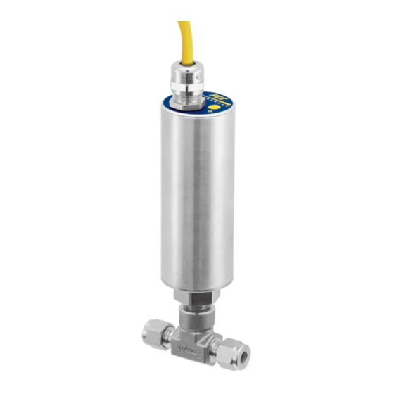
INSTRUMENT DESCRIPTION AND IDENTIFICATION The FS10A is a universal flow monitor and switch specifically designed for gas and liquid process analyzer sampling systems. The FS10A is a fast responding, highly repeatable sensor which installs easily into a standard tube tee fitting or SP76 (NeSSI) modular manifold. -
Page 7: Mounting Orientation
FS10 Series Mounting Orientation Left to Right Flow Example in 1/4 and 3/8 inch tube tees For optimum sensitivity in low flow applications, probes should be installed with the “A” (Active) sensor positioned upstream. “A” (Active) mark Horizontal lines: gas or liquid. Upstream Vertical lines: gas - flow must be down... -
Page 8: Instrument Wiring
Input Power, 24 Vdc FCI recommends installing an input power disconnect and a fuse near the instrument to interrupt power during installation, maintenance, calibra- tion, alarm selection and troubleshooting procedures. Conduit should also be installed according to the local electrical codes or hazardous location requirements. - Page 9 FS10 Series Fluid Components International LLC...
- Page 10 FS10 Series 8 WIRE CABLE FLOW ELEMENT FS10 ENCLOSURE FROM FLOW ELEMENT WITH POTTED CABLE M12, 8 PIN CONN PAIR 8 WIRE FEMALE / MALE SHIELDED REFERENCE ONLY CABLE ACT SENSE + ACT SENSE - ACT & REF DRIVE - REF DRIVE + REF SENSE + REF SENSE -...
-
Page 11: Switching Inductive Loads
Switching Inductive Loads If the FS10A relay contacts are to be used to energize or de-energize an external relay, diode suppression must be used across the external relay coil. Use the guidelines in the following example to select the proper diode. - Page 12 FS10 Series Fluid Components International LLC...
- Page 13 FS10 Series FS10 Flow Element Options Fluid Components International LLC...
- Page 14 FS10 Series FS10 Remote Enclosure and Connector Options Fluid Components International LLC...
-
Page 15: Set-Up And Operation
FS10 Series SET-UP AND OPERATION FS10 Function Overview The FS10 flow monitor may come configured for use as a flow or temperature meter. The output of the switch configuration is a SPDT relay contact or binary collector to ground [N-channel MOSFET] output (sync). A 4-20 mA output signal is also active as a signal reference. In the transmitter configu- ration, either the flow or temperature functions may be assigned to the 4-20 mA output. -
Page 16: Fs10 Field Quick Setup Procedure
In some cases the high liquid flow signal will saturate before reaching the high flow that is simulated, but the FS10A will save the highest value it is capable of sensing in that application and use it as the high end limit. -
Page 17: Fs10 Button Controls
Throttle flow valve to simulate zero and full scale flow. Press either button momentarily to save parameter values and exit into normal operating mode. * FS10A with Firmware version 4.0 or greater FS10 Button Controls It is recommended the unit be powered-up for 10-15 minutes before making changes to any of the flow settings. -
Page 18: Normal Set-Up And Operation Using The Button Interface
FS10 Series Button Operation Enter “function selection” Push and hold both buttons simultaneously 3 seconds Select desired “function” Push “+” or “-“ to step through (LEDs indicate function #) Enter “function adjust” Push and hold either “-“ or “+” button 3 seconds Adjust within function Follow instructions for particular function entry Exit “function adjust”... -
Page 19: Flow Switch Operation
FS10 Series Flow Switch Operation Units supplied without factory trip point setting should be scaled in situ before setting the trip point. Default Universal Setting A from Bank 1 is recommended for most low flow sampling gas or liquid service. Gas and liquid service applications where higher flow rate detection is required may select Universal Setting B from Bank 3. -
Page 20: Time Delay (Function 10 Or 11)
FS10 Series The hysteresis may be applied above the trip point or below the trip point. As an example, if set above the trip-point in an application requir- ing low flow detection, the relay will change state as the signal falls below the trip point, but will not reset until it reaches the trip-point value plus the added hysteresis value. -
Page 21: Output And Display Parameters
FS10 Series Output and Display Parameters Diagram 2 Fluid Components International LLC... - Page 22 FS10 Series Table 5 Button Controls 0 = LED off, 1 = LED on Function # Function LED Pattern for LED Pattern Parameter Description Name Parameter 1 – indicates current Trip Point 1000000000 Button controls adjust relay trip point in RELAY_LIMIT value relative to full Adjust...
- Page 23 FS10 Series Hysteresis 0000011111 = apply Selects whether the hysteresis is to be Applied 1111111100 RELAY_HYSTERESIS_ above applied above (default) or below the Above or EFFECT 1111100000= apply relay trip point. Pressing the buttons will Below Trip below toggle between the two options. Point Buttons adjust the value of the dead 1 –...
-
Page 24: Pc Interface And Command Line Interface Configurations
An RS232 to 9 pin serial (DB9) to USB interface cable is available from FCI to connect directly to a PC or PLC. An RS232 interface from either of the 3 configurations above is available from the table on the following page. NOTE: The USB interface cable is supplied with a device driver disk. -
Page 25: Pc Interface Software
FS10 Series PC Interface Software Typical screen shots using the Windows based PC interface DISPLAy WINDOW SET-UP WINDOW Move mouse cursor over description to uncover additional notes SET-UP / FLOW RANGE WINDOW SET-UP / SWITCH POINT SET-UP WINDOW Capture Zero and Full Scale Flow Set trip-point with Capture button or by entering % of span Fluid Components International LLC... - Page 26 FS10 Series SET-UP / CAL BANK SET-UP WINDOW SET-UP / TEMPERATURE RANGE WINDOW Saving/retrieving calibrations to and from banks Range temperature output if using 4-20 mA out as temperature indication DIAGNOSTICS WINDOW SET-UP / OUTPUT CONFIGURATION WINDOW Select 4-20 mA and LED mapping (flow or temperature) Fluid Components International LLC...
-
Page 27: Pc Interface Software
FS10 Series PC Interface Software Typical screen shots using the Windows based PC interface DIAGNOSTICS / CALIBRATION DIAGNOSTICS / RAW VALUES PARAMETERS WINDOW WINDOW QUICK SETUP UTILITIES / NAMUR SETTINGS Fluid Components International LLC... -
Page 28: Fs10 Serial Interface
FS10 Series FS10 Serial Interface Interface example using HyperTerminal set-up: HyperTerminal, which comes with Windows95, 98, Me, NT, 2K XP & Windows 7 and can be used to communicated directly with the FS10. To set up HyperTerminal to interface with computer modem: 1. - Page 29 FS10 Series 4. The COM port properties box comes up. Make sure that you set the Bits per second to 9600. The other defaults shown here are correct. Click OK. 5. You now get the HyperTerminal win- dow where you are able to control your modem with commands.
-
Page 30: Command Line Interface Commands
FS10 Series Command Line Interface Commands INFO Read version information (Hardware, Firmware, Date code, other values (#1.. #45). [The values in items 1 through 45 are listed] MEAS Read most recent flow measurement values (#220..#238). [The values in items 220 through 238 are listed] RCFG B Read configuration parameters (#80..#132) from bank B (0..9). - Page 31 FS10 Series Table 7 RS232 Interface Reference Table Password Bank Item # Item Name Description Type Size Default Level HW_REV Hardware Version FW_REV Firmware Revision Date Code, Year Date Code, Month Date Code, Date Sequence Number RESERVED1 Reserved 1 FREQ_MAX_OUT For output modes 2, 3, 6, &...
- Page 32 FS10 Series Table 7 RS232 Interface Reference Table continued Password Bank Item # Item Name Description Type Size Default Level QSM2_PERCENT_SPAN Default trip point level as percent of float Lev 2 established span BANK_ID Bank Identification char. Bank ID Lev 2 0..9 CUST_FLOW_MIN Customer Flow_Final Limit Min.
- Page 33 FS10 Series Table 7 RS232 Interface Reference Table continued Password Bank Item # Item Name Description Type Size Default Level 0..9 FLOW_K4 "K4" factor applied float Lev 2 0..9 CUST_TEMP_MIN Customer Temperature final float Lev 2 Min. limit 0..9 CUST_TEMP_MAX Customer Temperature final float Lev 2...
-
Page 34: Safety Instrumented Systems Requirements (Sis)
Bypass the safety function and take appropriate action to avoid a false trip. Send a command through PC interface or function buttons to the FS10A to de-energize the relay or transistor or go to the high alarm current output. Verify that the relay or transistor changes state or that the analog current reaches that value. -
Page 35: Product Repair
FCI service representative. If FCI representative cannot be reached, contact FCI Technical Service. If the instrument is to be returned, obtain a Return Authorization. The form contains a declaration of decontamination cleaning information that the instrument must comply with before it is shipped to FCI. The telephone number in the US is 1-800-854-1993 or 1-760-744-6950 or email: techsupport@fluidcomponents.com... - Page 36 FS10 Series Intentionally Left Blank Fluid Components International LLC...
-
Page 37: Appendix Aapprovals
11:53:50 -07'00' ______________________________________ Eric Wible, Engineering Manager Flow/Liquid Level/Temperature Instrumentation Visit FCI on the Worldwide Web: www.fluidcomponents.com 1755 La Costa Meadows Drive, San Marcos, California 92078 USA 760-744-6950 800-854-1993 760-736-6250 European Office: Persephonestraat 3-01 5047 TT Tilburg – The Netherlands – Phone 31-13-5159989 Fax 31-13-5799036 Doc no. - Page 38 FS10 Series Safety Instructions for the use the FS10 flowmeter in Hazardous Areas Approval KEMA 10ATEX0142 X / IECEx KEM 10.0067X for: Category II 3 G for Gas protection Ex nA IIC T4 Category II 3 D for Dust protection IP64 Ex tc IIIC T 81ºC Dc The FS10 series consist of a sensing element and associated integral or remote mounted electronics.
- Page 39 F B L Consignes de sécurité Ces consignes de sécurité sont valables pour le modèle FS10 de la société Fluid Components (FCI) conforme au certificat d’épreuves de type KEMA 10ATEX0142X/IECEx KEM10.0067(numéro du certificat sur l’étiquette signalétique) conçu pour les applications dans lesquelles un materiel de la catégorie II3GD est nécessaire.
- Page 40 FS10 Series Intentionally Left Blank Fluid Components International LLC...
-
Page 41: Appendix Bauxiliary Drawings
FS10 Series APPENDIX B AUXILIARy DRAWINGS Fluid Components International LLC... - Page 42 FS10 Series Fluid Components International LLC...
- Page 43 FS10 Series Fluid Components International LLC...
-
Page 44: Pc Interface Kits
FS10 Series PC Interface Kits Fluid Components International LLC... -
Page 45: 022083-02 Power Supply/Interface Box Kit
FS10 Series 022083-01 Power Supply/Interface Box 022083-02 Power Supply/Interface Box Kit PN 022083-01 Power Supply/Interface Box PN 021712-05 DB9 to USB Converter with USB PC driver disk PN 021712-04 2.5mm plug to DB9 PN 021438-06E02 interconnecting cable, 2 meters, M12(m) and M12(f) end connections PN 022411-01 M12 (M) to power leads #1 PWR and #2 RTN PN 022421-01 RS232 wire leads to 2.5mm receptacle FS10 PC interface software 09EN000209... -
Page 46: Pc Interface Components
FS10 Series PC Interface Components Relay Output 022474-A02 - 8 pin M12(F) connector with 6 feet [2 meter] pigtail and wire markers 022474-A05 - 8 pin M12(F) connector with 15 feet [5 meter] pigtail and wire markers 022474-A10 - 8 pin M12(F) connector with 30 feet [10 meter] pigtail and wire markers N-Channel MOSFET Output 022474-B02 - 8 pin M12(F) connector with 6 feet [2 meter] pigtail and wire markers 022474-B05 - 8 pin M12(F) connector with 15 feet [5 meter] pigtail and wire markers... -
Page 47: Board Connectors - Oem
FS10 Series Board Connectors - OEM Fluid Components International LLC... -
Page 48: Db9 Connection Schematic
FS10 Series DB9 Connection Schematic Wiring Schematic RS232 from Cable Pigtail to DB9 Female Connector DB9 Female Connector Wiring Schematic RS232 through 2.5mm Stereo Plug to DB9 Female Connector Fluid Components International LLC... -
Page 49: Appendix Ccustomer Service
Attn: Customer Service Department By Phone Contact the area FCI regional representative. If a field representative is unable to be contacted or if a situation is unable to be resolved, contact the FCI Customer Service Department toll free at 1 (800) 854-1993. -
Page 50: Extended Warranty
Contact an FCI field representative to request field service. A field service technician is dispatched to the site from either the FCI factory or one of the FCI representative offices. After the work is com- plete, the technician completes a preliminary field service report at the customer site and leaves a copy with the customer. -
Page 51: Return Authorization Request
Return Product Information Model No: ____________________________________ Serial No(s): ____________________________________ Failure Symptoms (Detailed Description Required) : ____________________________________________________ ____________________________________________________________________________________________ What Trouble Shooting Was Done Via Phone or Field Visit by FCI: _________________________________________ ____________________________________________________________________________________________ FCI Factory Technical Service Contact: _____________________________________________________________ Sensor Element ... - Page 52 FCI. Cleanliness of a returned item or acceptability of the MSDS shall be at the sole discretion of FCI. Any item returned which does not comply with this certification shall be returned to your location Freight Collect and at your risk.
- Page 53 FS10 Series WARRANTIES Goods furnished by the Seller are to be within the limits and of the sizes published by the Seller and subject to the Seller’s standard tolerances for variations. All items made by the Seller are inspected before shipment, and should any of said items prove defective due to faults in manufacture or performance under Seller approved applications, or fail to meet the written specifications accepted by the Seller, they will be replaced or repaired by Seller at no charge to Buyer provided return or notice of rejection of such material is made within a reasonable period but in no...
- Page 54 FS10 Series NOTES Fluid Components International LLC...
- Page 55 FS10 Series NOTES Fluid Components International LLC...
- Page 56 (and does not include manufacture or processing uses). Any other use is strictly prohibited without the prior written consent of FCI. © Copyright 2013 by Fluid Components International LLC. All rights reserved. FCI is a registered trademark of Fluid Components International LLC. Information subject to change without notice.
Need help?
Do you have a question about the FS10A and is the answer not in the manual?
Questions and answers