
Related Manuals for Phoenix Contact TC ROUTER 3002T-4G

Summary of Contents for Phoenix Contact TC ROUTER 3002T-4G
- Page 1 Industrial mobile router with integrated firewall and VPN User manual UM EN TC ROUTER ... 3G/4G...
- Page 2 TC ROUTER 3002T-3G 2.04.11 2702529 TC ROUTER 2002T-4G 2.04.11 2702530 TC ROUTER 2002T-3G 2.04.11 2702531 TC ROUTER 3002T-4G VZW 2.04.11 2702532 TC ROUTER 3002T-4G ATT 2.04.11 2702533 PHOENIX CONTACT GmbH & Co. KG • Flachsmarktstraße 8 • 32825 Blomberg • Germany phoenixcontact.com...
-
Page 3: Table Of Contents
Identification of warning notes ................5 Qualification of users ..................... 5 Field of application of the product................6 Safety notes ......................6 UL warning notes (only TC ROUTER 3002T-4G VZW and TC ROUTER 3002T-4G ATT)................7 Installation ..........................9 Product description....................9 Structure...................... - Page 4 Technical data ....................106 Dimensions......................110 Technical appendix.........................111 XML elements ....................111 Structure of the XML configuration file............... 114 Wireless network ....................117 CIDR (Classless Inter-Domain Routing) ............136 Appendixes..........................137 List of figures ..................... 137 Index........................141 4 / 146 PHOENIX CONTACT 107025_en_01...
-
Page 5: For Your Safety
– Qualified application programmers and software engineers. The users must be familiar with the relevant safety concepts of automation technology as well as applicable stan- dards and other regulations. 5 / 146 107025_en_01 PHOENIX CONTACT... -
Page 6: Field Of Application Of The Product
• Operation of the wireless system is only permitted if accessories available from Phoenix Contact are used. The use of other accessory components could invalidate the operating license. You can find the approved accessories for this wireless system listed with the product at phoenixcontact.net/products. -
Page 7: Ul Warning Notes (Only Tc Router 3002T-4G Vzw And Tc Router 3002T-4G Att)
For your safety UL warning notes (only TC ROUTER 3002T-4G VZW and TC ROUTER 3002T-4G ATT) • Use copper wires rated 85°C. • If the equipment is used in a manner not specified, the protection provided by the equip- ment may be impaired. - Page 8 TC ROUTER ... 3G/4G 8 / 146 PHOENIX CONTACT 107025_en_01...
-
Page 9: Installation
Europe TC ROUTER 2002T-4G 4G (LTE) 3G (UMTS/HSPA) 2G (GPRS/EDGE) TC ROUTER 2002T-3G 3G (UMTS/HSPA) 2G (GPRS/EDGE) TC ROUTER 3002T-4G VZW IPsec and OpenVPN, up USA (HazLoc 4G (LTE) to three VPN tunnels approval) TC ROUTER 3002T-4G ATT 3G (UMTS/HSPA) -
Page 10: Structure
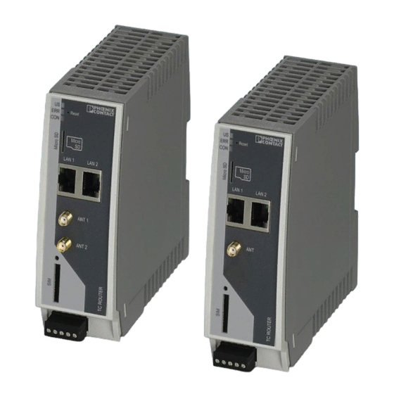
LAN interface 1 LAN interface 2 SMA antenna connection 1, primary antenna SMA antenna connection 2, secondary antenna COMBICON plug-in screw terminal block SIM interface Slot for microSD card CON LED ERR LED 10 US LED 10 / 146 PHOENIX CONTACT 107025_en_01... - Page 11 Searching for cellular network Connect Yellow Connection established In the case of the TC ROUTER 3002T..., the CON LED can be configured via web-based management. You can therefore monitor the mobile IP connection or the VPN tunnel. 11 / 146 107025_en_01 PHOENIX CONTACT...
-
Page 12: Mounting And Removal
Pull down the locking latch using a screwdriver, needle-nose pliers or similar. • Pull the bottom edge of the device slightly away from the mounting surface. • Pull the device away from the DIN rail. Figure 2-4 Removal 12 / 146 PHOENIX CONTACT 107025_en_01... -
Page 13: Inserting The Sim Card
Insert the SIM card so that the SIM chip remains visible. • Fully insert the SIM card holder together with the SIM card into the device until this ends flush with the housing. Figure 2-5 Removing the SIM card holder, inserting the SIM card 13 / 146 107025_en_01 PHOENIX CONTACT... -
Page 14: Connection
Check the signal quality in the web-based management software under “Device Infor- mation, Status, Radio”. • Fix the antenna in place when reception is good or very good. • Screw the antenna hand-tight on to the device (1.7 Nm). 14 / 146 PHOENIX CONTACT 107025_en_01... - Page 15 Connect the supply voltage to 24 V and 0 V at the plug-in screw terminal block. Ensure the correct polarity when doing so. • The device is ready for operation as soon as the US LED lights up. 15 / 146 107025_en_01 PHOENIX CONTACT...
- Page 16 The 0 V potential of the switching inputs and outputs must be connected to the “0 V” ter- minal block of the power supply connection. – 24V 0V I1 I2 O1 Figure 2-9 Wiring inputs 16 / 146 PHOENIX CONTACT 107025_en_01...
-
Page 17: Resetting The Router
Disconnect the Ethernet cable from the LAN connection on the router. • Reconnect the Ethernet cable. • Press and hold down the reset button for a further five seconds. The IP address is now reset to its default address (192.168.0.1). 17 / 146 107025_en_01 PHOENIX CONTACT... - Page 18 TC ROUTER ... 3G/4G 18 / 146 PHOENIX CONTACT 107025_en_01...
-
Page 19: Configuration Via Web-Based Management
For security reasons, we recommend you change the password during initial configura- tion (see “User (password change)” on page 85). There are two user levels: – user: read-only access to the “Device Information” menu item – admin: full access to all areas 19 / 146 107025_en_01 PHOENIX CONTACT... -
Page 20: Device Information (Viewing The Device Status)
Type of radio engine used Radio firmware Firmware version of the radio engine IMEI IMEI = International Mobile Station Equipment Identity 15-digit serial number that can be used to clearly identify each mobile network device 20 / 146 PHOENIX CONTACT 107025_en_01... -
Page 21: Status
Wrong PIN: wrong PIN stored in device – No SIM card: SIM card not inserted – Busy: radio engine starting – Power off: radio engine switched off Signal level Signal strength as a dBm value and bar 21 / 146 107025_en_01 PHOENIX CONTACT... - Page 22 4G mobile network via LTE IMSI IMSI = International Mobile Subscriber Identity, number used to clearly identify the user of a network Local area code Area code in the mobile network Cell ID Unique mobile phone cell ID 22 / 146 PHOENIX CONTACT 107025_en_01...
- Page 23 Sum of data sent since last login to the mobile network Local network LAN 1/2 – connected: LAN 1/2 connected – not connected: LAN 1/2 not connected IP address Current Ethernet IP address Netmask Netmask of the local Ethernet network 23 / 146 107025_en_01 PHOENIX CONTACT...
- Page 24 This page shows current status information and the configuration of the inputs and outputs. Figure 3-5 Status, I/O status 3.4.4 Routing table This page shows all entries of the routing table. Figure 3-6 Status, Routing table 24 / 146 PHOENIX CONTACT 107025_en_01...
- Page 25 This page shows the IP addresses that the mobile router has currently assigned to the DHCP clients. Figure 3-7 Status, DHCP leases 3.4.6 System info This page shows the current system utilization. Figure 3-8 Status, System info 25 / 146 107025_en_01 PHOENIX CONTACT...
-
Page 26: Local Network (Local Network Setup)
Using alias addresses, you can assign up to 8 additional IP addresses to the router. This means that the router can be ac- cessed from various subnetworks. Click on “New” and enter the desired IP address and subnet mask. 26 / 146 PHOENIX CONTACT 107025_en_01... - Page 27 DHCP server should assign IP addresses to locally con- nected devices. End of IP range End of DHCP area: the end of the address area from which the DHCP server should assign IP addresses to locally connected devices. 27 / 146 107025_en_01 PHOENIX CONTACT...
- Page 28 Figure 3-11 Local network, Static routes Local network, Static routes Local static routes Network Network in CIDR format, see “CIDR (Classless Inter-Domain Routing)” on page 136 Gateway Gateway via which this network can be accessed 28 / 146 PHOENIX CONTACT 107025_en_01...
-
Page 29: Wireless Network (Mobile Network Settings)
(in min- utes) Daily relogin – Disabled: daily login deactivated – Enabled: daily login activated Time Time at which the router logs out of the mobile network under controlled conditions and logs in again. 29 / 146 107025_en_01 PHOENIX CONTACT... - Page 30 Depending on your contract, this may incur ad- ditional costs. Alternatively, you can specify a provider. – Disabled: roaming is deactivated and only the provider's home network is used. If this network is unavailable, the router cannot establish an Internet connection. 30 / 146 PHOENIX CONTACT 107025_en_01...
- Page 31 Select the protocols for logging in to the provider: – None: the provider's APN does not require login (default). – Refuse MSCHAP: MSCHAP is not accepted. – CHAP only: Only CHAP is accepted. – PAP only: Only PAP is accepted. 31 / 146 107025_en_01 PHOENIX CONTACT...
- Page 32 TC ROUTER ... 3G/4G Settings for the US devices (TC ROUTER 3002T-4G VZW and TC ROUTER 3002T-4G ATT) The devices for the American market require special APN settings. Figure 3-14 Wireless network, SIM (US) Wireless network, SIM Settings for the primary mobile network connection, US...
- Page 33 Select the protocols for logging in to the provider: – None: the provider's APN does not require login (default). – Refuse MSCHAP: MSCHAP is not accepted. – CHAP only: Only CHAP is accepted. – PAP only: Only PAP is accepted. 33 / 146 107025_en_01 PHOENIX CONTACT...
- Page 34 Switch output n: ON/OFF, n={1...4} IPSEC Start or stop IPsec VPN 1: ON/OFF IPSEC:n Start or stop IPsec VPN n: ON/OFF, n={1...3} OPENVPN Start or stop VPN 1: ON/OFF OPENVPN:n Start or stop VPN n: ON/OFF, n={1...3} 34 / 146 PHOENIX CONTACT 107025_en_01...
- Page 35 Port to which the SMS message should be forwarded 1432) Example SMS message text for starting IPsec tunnel #2 with the password 1234: #1234:SET:IPSEC:2 To stop this connection, you must send the following SMS message: #1234:CLR:IPSEC:2 35 / 146 107025_en_01 PHOENIX CONTACT...
- Page 36 – Enabled: manual DNS setting is enabled. DNS server IP address of the primary DNS server in the mobile network Sec. DNS server IP address of the alternative DNS server in the mobile network 36 / 146 PHOENIX CONTACT 107025_en_01...
- Page 37 Wireless network, Wireless static routes Wireless network, wireless static routes Wireless static routes Network The network in CIDR format, see “CIDR (Classless Inter-Do- main Routing)” on page 136 Gateway Gateway via which this network can be accessed 37 / 146 107025_en_01 PHOENIX CONTACT...
- Page 38 User name for your DynDNS account DynDNS password Password for your DynDNS account DynDNS host name Host name that was specified for this router with the DynDNS service The router can be accessed via this host name. 38 / 146 PHOENIX CONTACT 107025_en_01...
- Page 39 Wireless network: the mobile network interface sends the connection monitoring IP packets with the IP address assigned by the provider. Check every Check interval in minutes Max. retry Number of times to retry until the configured action is per- formed 39 / 146 107025_en_01 PHOENIX CONTACT...
- Page 40 Relogin: shut down mobile network interface and restart by logging into the mobile network again. – None: no action As an option, you can configure information regarding the status of connection monitoring via a switching output. 40 / 146 PHOENIX CONTACT 107025_en_01...
- Page 41 IP address or host name of the reference point for monitoring Clear Clear log file in the router for a new monitoring session View View current log file Save Save log file on local computer 41 / 146 107025_en_01 PHOENIX CONTACT...
- Page 42 WCDMA HSDPA ONLINE WCDMA HSUPA ONLINE WCDMA HSDPA+HSUPA ONLINE LTE ONLINE Location lac= Location Area Code ci= mobile phone cell ID Current own IP address myip= Reference IP ping= Ping times in msd round-trip min/avg/max= (minimum/average/maximum) 42 / 146 PHOENIX CONTACT 107025_en_01...
-
Page 43: Network Security (Security Settings)
Drop invalid packets The firewall of the mobile router can filter and drop invalid or damaged IP packets. – Disabled: invalid IP packets are also sent. – Enabled: invalid IP packets are dropped (default). 43 / 146 107025_en_01 PHOENIX CONTACT... - Page 44 Disabled: the SSH service is not available. No external access to the router via SSH (default) – Enabled: external access to the router via the SSH ser- vice is possible, from the local network or via a VPN tun- nel. 44 / 146 PHOENIX CONTACT 107025_en_01...
- Page 45 CIDR format (see “CIDR (Classless Inter-Domain Rout- ing)” on page 136). From port / To port (Only evaluated for TCP and UDP protocols) – any: any port – startport-endport: a port range (e.g., 110 ... 120) 45 / 146 107025_en_01 PHOENIX CONTACT...
- Page 46 No: event is not logged (default). – New: add a new firewall rule below the last rule. – Delete: delete rule from the table. The arrows can be used to move the respective rule one row up/down. 46 / 146 PHOENIX CONTACT 107025_en_01...
- Page 47 For each individual firewall rule you can specify whether the event is to be logged if the rule is applied. – Yes: event is logged. – No: event is not logged (default). 47 / 146 107025_en_01 PHOENIX CONTACT...
- Page 48 Internet are given the IP address of the router. A response via the Internet is possible, even without a de- fault gateway. – No: a response via the Internet is only possible with the default gateway (default). 48 / 146 PHOENIX CONTACT 107025_en_01...
- Page 49 No: event is not logged (default). – New: add a new firewall rule below the last rule. – Delete: delete rule from the table. The arrows can be used to move the rule one row up or down. 49 / 146 107025_en_01 PHOENIX CONTACT...
- Page 50 Disabled: a response via the Internet is only possible with the default gateway (default). Log traffic to exposed Specify whether IP connections are logged. host – Enabled: IP connections are logged. – Disabled: IP connections are not logged (default). 50 / 146 PHOENIX CONTACT 107025_en_01...
- Page 51 The device supports a maximum of 16 rules for IP masquerading. Figure 3-26 Network security, Masquerading Network security, masquerading Masquerading From IP 0.0.0.0/0 means all IP addresses. To specify an address area, use CIDR format (see “CIDR (Classless Inter-Domain Rout- ing)” on page 136). 51 / 146 107025_en_01 PHOENIX CONTACT...
-
Page 52: Vpn
The following functions are supported for OpenVPN connections: – OpenVPN Client – TUN device – Authentication via X.509 certificate or pre-shared secret key (PSK) – Static key – TCP and UDP transmission protocol – Keep Alive 52 / 146 PHOENIX CONTACT 107025_en_01... - Page 53 Click on Edit to specify the settings for IPsec (see Page 54). Internet Key Exchange protocol for automatic key manage- ment for IPsec Click on Edit to specify the settings for IKE (see Page 58). 53 / 146 107025_en_01 PHOENIX CONTACT...
- Page 54 “Remote host” is only used if “Initiate” has been selected under “Remote connection” (the router establishes the con- nection). If “Remote connection” is set to “Accept”, the value “%any” is set internally for “Remote host”. It therefore waits for a connec- tion. 54 / 146 PHOENIX CONTACT 107025_en_01...
- Page 55 One of the “Subject Alternative Names”, if they are listed in the certificate. If the certificate contains “Subject Alter- native Names”, these are specified under “Valid values”. These can include IP addresses, host names with “@” prefix or e-mail addresses, for example. 55 / 146 107025_en_01 PHOENIX CONTACT...
- Page 56 1:1 NAT. You can use this function, for ex- ample, to access two machines with the same IP address via a VPN tunnel. 56 / 146 PHOENIX CONTACT 107025_en_01...
- Page 57 Initiate on call: VPN tunnel is started via a call. You must also specify the number of minutes until the VPN tunnel is to be stopped via Autoreset. – Initiate on XML: VPN tunnel is started or stopped via an XML command via socket server. 57 / 146 107025_en_01 PHOENIX CONTACT...
- Page 58 The longer the key, the more time-consuming the encryption pro- cedure. ISAKMP SA hash Leave this set to SHA-1/MD5. It then does not matter whether the peer works with MD5 or SHA-1. 58 / 146 PHOENIX CONTACT 107025_en_01...
- Page 59 Behavior in the event that the IPsec connection is aborted: – Off: no DPD – On: DPD activated – in “Restart” mode for VPN Initiate – in “Clear” mode for VPN Accept 59 / 146 107025_en_01 PHOENIX CONTACT...
- Page 60 This can be a self- signed or CA-signed machine certificate. To use a certificate that is installed, the certificate must be assigned under “VPN, IPsec, Connections, Settings, Edit“. Click on “Apply” to load the certificate onto the router. 60 / 146 PHOENIX CONTACT 107025_en_01...
- Page 61 “Remote certificate“ “Local cer- tificate“ can be assigned to each VPN connection. Password: password used to protect the private key of the PKCS#12 file. The password is assigned when the key is ex- ported. 61 / 146 107025_en_01 PHOENIX CONTACT...
- Page 62 CA certificate, a machine certificate or a private key. 3.8.3 IPsec status (status of the VPN connection) Figure 3-31 VPN, IPsec, Status VPN, IPsec, Status IPsec status Active IPsec Status of the active VPN connection connections 62 / 146 PHOENIX CONTACT 107025_en_01...
- Page 63 Tunnel Click on “Edit” to specify the settings for OpenVPN (see “Tun- nel, Edit” on page 64). Advanced Click on “Edit” to specify advanced settings for OpenVPN (see “Advanced, Edit” on page 67). 63 / 146 107025_en_01 PHOENIX CONTACT...
- Page 64 Initiate on Input #1 ... #2: manual start via switching input Remote host IP address or URL of the peer to which the tunnel will be cre- ated. Remote port Port of the peer to which the tunnel will be created (default: 1194) 64 / 146 PHOENIX CONTACT 107025_en_01...
- Page 65 IP address enables the IP addresses for the remote net- work to be accessed through the VPN tunnel. You must enter the same settings as the remote network on the remote VPN router. 65 / 146 107025_en_01 PHOENIX CONTACT...
- Page 66 Duration in seconds after which the connection to the peer should be restarted if there has been no response to the Keep Alive requests. Default: 120 seconds Only if “Local 1:1 NAT” is activated. 66 / 146 PHOENIX CONTACT 107025_en_01...
- Page 67 Lifetime in seconds of the agreed keys. interval Default: 3600 seconds (one hour) The keys of the OpenVPN connection are renewed at defined intervals in order to increase the difficulty of an attack on the OpenVPN connection. 67 / 146 107025_en_01 PHOENIX CONTACT...
- Page 68 The CA certificate must be in crt format. Click on the “Browse” button to select the certificate to be imported. Under “VPN, OpenVPN, Connections, Tunnel, Edit“, Local Certificate, one of these certificates can be assigned to each VPN connection. 68 / 146 PHOENIX CONTACT 107025_en_01...
- Page 69 Generate static key Generates a key for the OpenVPN connection. You can store this key locally on the computer. Load static key Loads the key on the mobile router. Static keys Keys stored in the router 69 / 146 107025_en_01 PHOENIX CONTACT...
- Page 70 TC ROUTER ... 3G/4G 3.8.7 OpenVPN status (status of the VPN connection) Figure 3-37 VPN, OpenVPN, Status VPN, OpenVPN, Status Open VPN status Active OpenVPN Status of the active VPN connection connections 70 / 146 PHOENIX CONTACT 107025_en_01...
- Page 71 The inputs can be used to send alarms by SMS or e-mail. Each input can be configured in- dividually. Please note that inputs that are used to start a VPN connection, for example, can- not also be used to send alarms. Figure 3-38 I/O, Inputs 71 / 146 107025_en_01 PHOENIX CONTACT...
- Page 72 Enter the following for an SMS message: – Recipient from the phonebook – Message text Enter the following for an e-mail alert: – To: recipient – Cc: recipient of a copy – Subject – Message text 72 / 146 PHOENIX CONTACT 107025_en_01...
- Page 73 – Connection lost: the output is switched if the router con- nection check does not reach the configured reference address. Autoreset Duration in minutes until the output is reset automatically 73 / 146 107025_en_01 PHOENIX CONTACT...
- Page 74 TC ROUTER ... 3G/4G 3.9.3 Phonebook Enter phone numbers here: – For the recipients of alarm SMS messages – For those authorized to switch the outputs Figure 3-40 I/O, Phonebook 74 / 146 PHOENIX CONTACT 107025_en_01...
- Page 75 Character which creates a line break in the XML file – LF: line feed, line break after 0x0A (hex) – CR: carriage return, line break after 0x0D (hex) – CR+LF: line break after carriage return, followed by a line feed 75 / 146 107025_en_01 PHOENIX CONTACT...
- Page 76 Make sure that the XML data does not contain any line breaks. Query outputs and inputs Request state of output 1 Request state of input 1 Response from the router (shown with line break): State output 1 State input 1 76 / 146 PHOENIX CONTACT 107025_en_01...
- Page 77 Under "Event", select the option "Initiate on XML". ⇒ You can now switch on the data connection of the router through XML. Switch on data connection Response from the router (shown with line break): Connection on 77 / 146 107025_en_01 PHOENIX CONTACT...
- Page 78 You can read status information from the device: Request device data Data for the wireless connection (mobile devices only) Request data for the Internet connection Logical states at the connections Response from the router (shown with line break): 78 / 146 PHOENIX CONTACT 107025_en_01...
- Page 79 The response means that an SMS message has not been received yet. The following error codes are possible: Empty = no SMS message received Busy = try again later System error = communication problem with the radio engine 79 / 146 107025_en_01 PHOENIX CONTACT...
- Page 80 Send e-mails Send XML data with the following structure to the device IP address via Ethernet: Response from the router (shown with line break): Response from the router in the event of an error: 80 / 146 PHOENIX CONTACT 107025_en_01...
- Page 81 To start and stop IPsec and OpenVPN connections, send XML data with the following struc- ture to the device IP address via Ethernet: Start IPsec connection 2 Start OpenVPN connection Response from the router (shown with line break): 81 / 146 107025_en_01 PHOENIX CONTACT...
-
Page 82: System
The web-based management of the router can be accessed via this port using HTTPS (default: 443). Certificate validity Specify the validity period of the certificate for HTTPS access to web-based management here (default: 1825 days). 82 / 146 PHOENIX CONTACT 107025_en_01... - Page 83 The configuration will be de- leted. Connect LED function – Internet connectivity: packet data connection via mobile network active – VPN connectivity: VPN connection active (IPsec or OpenVPN) 83 / 146 107025_en_01 PHOENIX CONTACT...
- Page 84 If energy-saving mode is active, mobile communication is no longer possible. Ethernet LAN1/2: energy-saving mode deactivates Ethernet interface LAN 1/2. If energy-saving mode is active, communi- cation is no longer possible via this interface. 84 / 146 PHOENIX CONTACT 107025_en_01...
- Page 85 User setup Admin Unrestricted access to all areas – Old password – New password – Retype new password User Restricted access (read-only) Default: public – Old password – New password – Retype new password 85 / 146 107025_en_01 PHOENIX CONTACT...
- Page 86 System, Log file System, log file Log file Clear Delete all entries in the log file View View log file in the browser window Save Save log file as text file on local computer 86 / 146 PHOENIX CONTACT 107025_en_01...
- Page 87 Password for read access via SNMP Read and write Password for read and write access via SNMP Enable SNMPv3 – Yes: SNMP Version 3 is used. access – No: the service is deactivated (default). 87 / 146 107025_en_01 PHOENIX CONTACT...
- Page 88 E-mail configuration To send alarms by e-mail, the e-mail server via which these alerts are sent can be config- ured here. The e-mail server must support the SMTP protocol. Figure 3-46 System, E-mail configuration 88 / 146 PHOENIX CONTACT 107025_en_01...
- Page 89 User name and password are transmitted in encrypted form. User name User name for login to the e-mail server Password Corresponding password for login to the e-mail server From E-mail address of the sender 89 / 146 107025_en_01 PHOENIX CONTACT...
- Page 90 (cfg format or XML format). Reset to factory Click on “Apply” to reset the router to the default state upon de- defaults livery. This will reset all settings, including IP settings. Imported certificates remain unaltered. 90 / 146 PHOENIX CONTACT 107025_en_01...
- Page 91 The time is therefore adjusted as accurately as possible. Only then can the router act as the NTP serv- er for the devices connected to the LAN interface. The router then provides the system time. 91 / 146 107025_en_01 PHOENIX CONTACT...
- Page 92 Select the time zone. Daylight saving time – Enabled: daylight savings is taken into account. – Disabled: daylight savings is not taken into account. Time server for local Time server for the local network network 92 / 146 PHOENIX CONTACT 107025_en_01...
- Page 93 Choose the digital input with the “High” signal which will be used to restart the router if required. Make sure that following a restart the signal is “Low” again. This ensures that the router starts up normally. 93 / 146 107025_en_01 PHOENIX CONTACT...
- Page 94 Wait until the update is completed and the router restarts automatically. Do not start the router manually. Do not interrupt the power supply during the up- date process. Package update If necessary you can also just update individual router func- tions. 94 / 146 PHOENIX CONTACT 107025_en_01...
-
Page 95: Creating X.509 Certificates
Start the setup file. Follow the instructions in the setup program. Creating a new database • Start the XCA program. • Create a new database via “File, New Database”. Figure 4-1 Creating a new database 95 / 146 107025_en_01 PHOENIX CONTACT... -
Page 96: Creating A Ca Certificate
Switch to the “Certificates” tab and create a new certificate. In the program window shown, there is already a preset self-signed certificate with the sig- nature algorithm SHA-1. Figure 4-3 Creating a new CA certificate 96 / 146 PHOENIX CONTACT 107025_en_01... - Page 97 On the “Subject” tab, enter the information about the owner of the root certificate. Figure 4-4 Entering information about the owner • Create a key for this certificate. The default name, key type, and key size can be re- tained. Figure 4-5 Creating a key 97 / 146 107025_en_01 PHOENIX CONTACT...
- Page 98 Setting the validity and type for the CA certificate • Click OK. The certificate is created. A new root certificate from which further machine certificates can be derived now appears in the overview. Figure 4-7 CA certificate created 98 / 146 PHOENIX CONTACT 107025_en_01...
-
Page 99: Creating Templates
The name must be specified in the relevant certificates. The text specified in the angle brackets is a placeholder which is replaced when the template is applied. Figure 4-9 Creating a template, entering information about the owner 99 / 146 107025_en_01 PHOENIX CONTACT... - Page 100 Creating a template, entering the validity and type of certificate • Click OK. The template is created. You can now use the template as a basis to create certificates signed by the root certificate. 100 / 146 PHOENIX CONTACT 107025_en_01...
-
Page 101: Creating Certificates
A program window opens. On the “Source” tab, the root certificate that is to be used for signing is specified. In addition, you can select a template that was created earlier. The data is imported when you click on “Apply all”. Figure 4-11 Creating a certificate 101 / 146 107025_en_01 PHOENIX CONTACT... - Page 102 Creating a certificate, “Subject” tab • Create a new private key for this certificate. Figure 4-13 Creating a key for a certificate • Click OK. You have now created a machine certificate signed by the Certification Authority (CA). 102 / 146 PHOENIX CONTACT 107025_en_01...
-
Page 103: Exporting Certificates
The complete certificate, including the private key and the CA certificate, must be in “PKCS #12 with Certificate Chain” format. You can then upload it to the relevant device as a ma- chine certificate. Figure 4-15 Exporting a certificate 103 / 146 107025_en_01 PHOENIX CONTACT... - Page 104 Figure 4-16 Entering the password • The certificate for the partner must also be exported. This certificate is stored in PEM format without the private key. Figure 4-17 Exporting the partner certificate 104 / 146 PHOENIX CONTACT 107025_en_01...
-
Page 105: Technical Data
GPRS/EDGE, 2 Ethernet interfaces, firewall, NAT, SMA-F antenna socket Industrial LTE 4G router, version for Verizon Wireless TC ROUTER 3002T-4G VZW 2702532 (US), 2 Ethernet interfaces, firewall, NAT, IPsec and OpenVPN support, 2x SMA-F antenna socket Industrial LTE 4G router, version for AT&T (US), fallback... -
Page 106: Technical Data
RJ45 socket, shielded Serial transmission speed 10/100 Mbps, auto-negotiation Transmission length 100 m (twisted pair, shielded) Supported protocols TCP/IP, UDP/IP, FTP, HTTP(S) Secondary protocols ARP, DHCP, PING (ICMP), SNMP V1/V2, SMTP(S), NTP, SSL/TLS, STARTTLS 106 / 146 PHOENIX CONTACT 107025_en_01... - Page 107 50 Ω impedance SMA antenna socket SIM interface 1.8 V, 3 V GPRS Class 12, Class B CS1 ... CS4 EDGE Multislot Class 10 UMTS HSPA 3GPP R9 HSPA 3GPP R7 HSPA 3GPP R9 CAT4 CAT4 CAT4 107 / 146 107025_en_01 PHOENIX CONTACT...
- Page 108 (maximum transmission power of 23 dBm) 23 dBm) Ambient temperature -40°C ... 85°C (storage/transport) Permissible humidity (operation) 30% ... 95% (non-condensing) Permissible humidity 30% ... 95% (non-condensing) (storage/transport) Altitude 5000 m (for restrictions see manufacturer's declaration) 108 / 146 PHOENIX CONTACT 107025_en_01...
- Page 109 Technical data Approvals TC ROUTER 3002T-4G TC ROUTER 3002T-4G VZW TC ROUTER 3002T-3G TC ROUTER 3002T-4G ATT TC ROUTER 2002T-4G TC ROUTER 2002T-3G Conformance CE-compliant Noxious gas test ISA-S71.04-1985 G3 Harsh Group A UL, USA/Canada Class I, zone 2, AEx nA IIC T4 / Ex nA IIC T4 Gc Class I, Div.
-
Page 110: Dimensions
July 12,1999 Radio - effective use of the frequency spectrum and avoid- DIN EN 301511 ance of radio interference Dimensions 127,5 RESET Micro LAN 1 LAN 2 ANT 1 ANT 2 Figure 5-1 Dimensions 110 / 146 PHOENIX CONTACT 107025_en_01... -
Page 111: A Technical Appendix
Location Area Code (LAC) of the device in a mobile network (hexadecimal number, maximum of 4 digits) Cell ID, unique identification of the radio cell within the LAC (hexadecimal number, maximum of 8 digits) 111 / 146 107025_en_01 PHOENIX CONTACT... - Page 112 The UTF-8 coded text is specified in the element content. The text may con- sist of characters that are defined in the GSM 03.38 6.2.1 default alphabet. However, coding must be in UTF-8 as per XML rules. 112 / 146 PHOENIX CONTACT 107025_en_01...
- Page 113 Decimal number 1 ... 6 value Returned data type depending on server configuration. Both variants are recognized to set or reset outputs: Verbose Response in words, e.g., on/off Numeric Short numerical response, e.g., 1/0 113 / 146 107025_en_01 PHOENIX CONTACT...
-
Page 114: A 2 Structure Of The Xml Configuration File
./ipaddr IPv4 address of the device ./netmask IPv4 netmask ./proto Type of address assignment: “static” or “dhcp” ./ipalias This value represents a special list and should only be modified via the configuration page. 114 / 146 PHOENIX CONTACT 107025_en_01... - Page 115 Not used at present, must not be modified ./options Not used at present, must not be modified Static routes ./sroute List of local static routes This list should only be modified via the configuration page. 115 / 146 107025_en_01 PHOENIX CONTACT...
- Page 116 ./v3_enable Activate SNMPv3 The values represent a special list and should only be modified via the configuration page ./fw_local List of firewall rules for local data ./fw_external List of firewall rules for external data 116 / 146 PHOENIX CONTACT 107025_en_01...
-
Page 117: A 3 Wireless Network
Code of the selected provider Auto ./username User name for packet data network access ./password Password for packet data network access ./apn APN access point of the provider ./authallow Bit mask for permitted access protocols 117 / 146 107025_en_01 PHOENIX CONTACT... - Page 118 TC ROUTER ... 3G/4G SMS configuration ./sms_control Control device via SMS ./sms_password Password used for control ./sms_forward Forward received SMS message to a server ./sms_server IP address of the SMS server ./sms_port SMS server port 118 / 146 PHOENIX CONTACT 107025_en_01...
- Page 119 Reserved (do not use) Control via XML server 4 ... 5 Control via input 1 ... 2 Static routes ./sroute List of local static routes. This list should only be modified via the con- figuration page. 119 / 146 107025_en_01 PHOENIX CONTACT...
- Page 120 Hurricane Electric ./server Server URL for the custom DynDNS server ./username User name for the DynDNS service ./password Password for the DynDNS service ./hostname Own host name which is registered for the DynDNS service 120 / 146 PHOENIX CONTACT 107025_en_01...
- Page 121 Reconnect to GSM/UMTS network (Relogin) Monitoring ./log_enable Activate monitoring ./log_duration Monitoring duration in hours ./log_interval Time between two echo requests ./log_ping URL or IP address of a host that should respond to the echo requests 121 / 146 107025_en_01 PHOENIX CONTACT...
- Page 122 Perform IP masquerading at the external interface ./xssh External device access via SSH ./xwbm External device access via HTTP or HTTPS ./enable Device access via SSH ./port Port used for SSH access, normally 22 122 / 146 PHOENIX CONTACT 107025_en_01...
- Page 123 List of firewall rules for the NAT table (port forwarding) ./nat_vs List of forwarding rules for the NAT table (port forwarding) A 3.2 A 3.2.1 IPsec Higher-level settings ./enableupdate Monitoring of IP address changes ./autoupdate Monitoring interval in seconds 123 / 146 107025_en_01 PHOENIX CONTACT...
- Page 124 ./local_cert Local certificate ./remote_id Partner ID ./local_id Own ID ./remote_addr Partner tunnel end ./local_addr Local tunnel end ./psk Pre-shared key ./nat Connection NAT None Local 1:1 NAT Remote masquerading ./local_net Target of local NAT 124 / 146 PHOENIX CONTACT 107025_en_01...
- Page 125 Time in seconds after which the key is renegotiated ./esp_crypt Phase 2 IPsec SA encryption, valid values: 3des, aes128, aes192, aes256 ./esp_hash Phase 2 IPsec SA hash SHA-1 ./esp_life Time in seconds after which the key is renegotiated 125 / 146 107025_en_01 PHOENIX CONTACT...
- Page 126 Number of attempts to establish a connection Unlimited ./rekeyfuzz Value as a percentage ./rekeymargin Time in seconds A 3.2.2 Certificates ./cacerts/* CA certificates ./certs/local/* Local certificates ./certs/remote/* Partner certificates ./private/* Private key ./ldir/* Bit mask for certificate validity 126 / 146 PHOENIX CONTACT 107025_en_01...
- Page 127 Start immediately Control via SMS message Control via call Control via XML server 4...5 Control via input 1 ... 2 ./host URL or IP address of the partner ./rport Used partner port ./proto Protocol 127 / 146 107025_en_01 PHOENIX CONTACT...
- Page 128 Pre-shared key ./username User name ./password Password ./remote_ifc Partner tunnel end ./local_ifc Local tunnel end ./remote_addr Partner tunnel network ./nat Connection NAT None Local 1:1 NAT Local masquerading Remote masquerading Port forwarding Host forwarding 128 / 146 PHOENIX CONTACT 107025_en_01...
- Page 129 Size of packets with MSSFIX ./reneg_sec Time in seconds for renewing the key Port forwarding The values represent a special list and should only be modified via the configuration page. .napt List of settings for port forwarding 129 / 146 107025_en_01 PHOENIX CONTACT...
- Page 130 ./ldir/* Bit mask for certificate validity ./casonly/* CA certificates for authentication with user name and password Static keys ./ keys/* Static keys Diffie-Hellman parameters ./dh1024.pem DH parameter, 1024 bits ./dh2048.pem DH parameter, 2048 bits 130 / 146 PHOENIX CONTACT 107025_en_01...
- Page 131 Bit mask for phonebook selection ./sms/message SMS text ./email/to Recipient of the message ./email/cc Recipient of a copy ./email/subject Subject ./email/message Text message ./alarm_enable Activate alarm ./alarm_time Automatic reset time for the alarm in minutes 131 / 146 107025_en_01 PHOENIX CONTACT...
- Page 132 Remote controlled Radio Network Packet Service VPN Service Incoming Call Connection Lost Alarm ./autoreset Automatically reset alarm ./time Time in minutes to reset the alarm Phonebook ./n[xx] Telephone number in national or international format 132 / 146 PHOENIX CONTACT 107025_en_01...
- Page 133 Port used for the web server for HTTPS ./logremote Send log data to a log server ./logserver IP address of the log server ./logport Log server port ./lognvm Reserved, must be set to 0 133 / 146 107025_en_01 PHOENIX CONTACT...
- Page 134 Commands before PIN entry (without prefixed AT) ./gsm/at2cmd Commands after PIN entry (without prefixed AT) ./gprs/at1cmd Commands before PPP dial-in (without prefixed AT) ./gprs/dialup Dial-in into the packet data network that is used (not used at present) 134 / 146 PHOENIX CONTACT 107025_en_01...
- Page 135 Make own time available to the local network Reboot ./rebootenable Bit mask of weekdays on which a reboot should be performed ./reboottime Time for the reboot ./rebootevent Selected event for a reboot None 1 ... 2 Triggered by the relevant input 135 / 146 107025_en_01 PHOENIX CONTACT...
-
Page 136: A 4 Cidr (Classless Inter-Domain Routing)
CIDR notation. This may be necessary when configuring the firewall, for example. In the table below, the left-hand column shows the IP netmask, while the far right-hand column shows the corresponding CIDR notation. IP netmask binary CIDR Example: 192.168.1.0/255.255.255.0 corresponds to CIDR: 192.168.1.0/24 136 / 146 PHOENIX CONTACT 107025_en_01... -
Page 137: Appendixes
Wireless network, Monitoring .............. 41 Figure 3-21: Network security, General setup ............43 Figure 3-22: Network security, Firewall ..............45 Figure 3-23: Network security, SNMP Firewall ............47 Figure 3-24: Network security, IP and port forwarding ..........48 137 / 146 107025_en_01 PHOENIX CONTACT... - Page 138 Figure 4-9: Creating a template, entering information about the owner ....99 Figure 4-10: Creating a template, entering the validity and type of certifica- te ....................... 100 Figure 4-11: Creating a certificate ................. 101 138 / 146 PHOENIX CONTACT 107025_en_01...
- Page 139 Selecting a certificate for export ............103 Figure 4-15: Exporting a certificate ............... 103 Figure 4-16: Entering the password ..............104 Figure 4-17: Exporting the partner certificate ............104 Figure 5-1: Dimensions ..................110 139 / 146 107025_en_01 PHOENIX CONTACT...
- Page 140 TC ROUTER ... 3G/4G 140 / 146 PHOENIX CONTACT 107025_en_01...
-
Page 141: Index
Structure..............42 DIN rail ................ 12 See DIN rail Download managed application APN .......... 33 See Configuration up-/download managed Internet APN..........33 DPD (Dead Peer Detection) ........59 Masquerading ............. 51 DynDNS (dynamic DNS)..........38 141 / 146 107025_en_01 PHOENIX CONTACT... - Page 142 Technical data ............106 Radio status ..............21 Time settings Reboot ................ 93 See Date/time Redirection of data packets......... 28 Tunnel Removal..............12 See VPN tunnel Reset ................17 Resetting to the default settings See Reset 142 / 146 PHOENIX CONTACT 107025_en_01...
- Page 143 Web-based management Login ..............19 Starting..............19 Wireless network............29 Wireless static routes ..........37 X.509 certificate ............ 60, 95 XCA ................95 XML configuration file..........114 XML element............. 111 XML file format ............114 143 / 146 107025_en_01 PHOENIX CONTACT...
- Page 144 TC ROUTER ... 3G/4G 144 / 146 PHOENIX CONTACT 107025_en_01...
- Page 145 The receipt of technical documentation (in particular user documentation) does not constitute any further duty on the part of Phoenix Contact to furnish information on modifications to products and/or technical documentation. You are responsible to verify the suitability and intended use of the products in your specific application, in particular with regard to observing the applicable standards and regulations.
- Page 146 Should you have any suggestions or recommendations for improvement of the contents and layout of our manuals, please send your comments to: tecdoc@phoenixcontact.com 146 / 146 PHOENIX CONTACT GmbH & Co. KG • Flachsmarktstraße 8 • 32825 Blomberg • Germany phoenixcontact.com...
Need help?
Do you have a question about the TC ROUTER 3002T-4G and is the answer not in the manual?
Questions and answers