Table of Contents
Advertisement
Advertisement
Table of Contents

Subscribe to Our Youtube Channel
Related Manuals for MAHLE ACX1180


Summary of Contents for MAHLE ACX1180
- Page 1 MAHLE ACX1180 Original instructions AC Service Units...
-
Page 2: Table Of Contents
2 | ACX1 1 8 0 | Cont ent s Com m issioning Removing transportation packaging Sym bols use Attaching handle In the documentation ACX1180 1.1.1 Warning notices—Structure and meaning 4 4.3.1 Setting language 1.1.2 Symbols in this documentation 4.3.2... -
Page 3: Acx1 1 8 0 | 3
(Refrigerant identi cation unit) 7.10 Resetting the circuit breaker 7.11 System information 7.12 Spare and wearing parts 7.12.1 ACX1180 7.12.2 Refrigerant identi cation unit Disposal Disposal of electronic parts Disposal of LCD screen Disposal of refrigerants, UV dye, lubricants and oils... -
Page 4: Sym Bols Use
Practical hints and other useful information. Copyr ight Multi-step Instruction consisting of several steps. Software and data are the property of MAHLE or its sup- operation pliers and protected against copying by copyright laws, One-step Instruction consisting of one step. -
Page 5: Obligation Of Contractor
Whatever the event, MAHLE liability is re- out. stricted to the amount for which the customer actually pays for this product. -
Page 6: Safety Regulations
The ACX1180 must always be transported in its operat- The ACX1180 is provided with a refrigerant identification ing position. Never lay the ACX1180 on its side, as oil system designed to prevent contamination with other could then escape from the vacuum pump or the built in refrigerants. -
Page 7: Acx1 1 8 0 | 7
ACX1180 must be connected to a properly grounded electrical connection. If there is damage to the ACX1180, terminate usage im- mediately and contact customer service. The service hoses and service quick-release couplings must be regularly checked for wear and replaced if dam- aged. -
Page 8: Pr Oduc T Desc R Ipt Ion
Flushing. Refrigerant identification. The ACX1180 can only be operated with R134a. The ACX1180 is not to be used for service work on vehicles with air conditioning systems employing refrigerants other than R134a, as this will cause damage. Prior to A/C service check the type of refrigerant used in the vehicle air conditioning system. -
Page 9: Description Of Unit
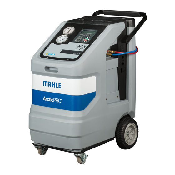
Spare refrigerant bottle/Flush device storage shelf Fig. 1: Front view Rear handle and grip Tool tray and storage Display and operating unit Front handle ACX1180 front housing Locking caster Rear wheel Service door Vacuum pump sight glass viewing window 10 USB port Fig. 3: Left-rear view 1. -
Page 10: Selection And Function Keys
TechALERT mounting area (Accessory) Selection and function keys Various functions are assigned to the function keys in the Refrigerant identi er (Accessory) ACX1180 software. The functions of the keys are defined in Printer (Accessory) the menu line of the ACX1180 software. Low-pressure gauge... -
Page 11: Printer (Optional)
Tools can be placed on the upper cover. The housing of the ACX1180 was designed with a built- in ventilation fan to prevent the accumulation of poten- The service door on the side provides access to the the tially flammable R134a refrigerant vapors. -
Page 12: Oil Bottles
To remove the service quick-release couplings from the parking/flush coupler, (Fig. 8, Pos. 2), press the coupling slightly towards the connection and carefully pull the knurled section back to unfasten it from the coupler. © MAHLE... -
Page 13: Inline Lters
3 .3 .7 Inline f ilt er s unit (Opt ional) The service hoses are connected to the ACX1180 by way of the inline filters. The inline filters prevent the ingress of fine The refrigerant identification unit permits precise determina- particles into the internal hydraulic circuit of the ACX1180. -
Page 14: Functional Description
The vehicle air conditioning system is partly filled with UV The ACX1180 can be used to perform a fully automatic A/C dye to facilitate the detection of leaks in the event of dam- service. The technician will be prompted for entry of data age to the vehicle air conditioning system. -
Page 15: Com M Issioning
Rem oving t r anspor t at ion pac k aging mounting spacers. When removing the packaging, use care to ensure there is no damage caused to the ACX1180 unit or any of the included accessories. 1. Remove the cardboard box. -
Page 16: Acx1180
Set up 4 .4 .1 Selec t able Opt ions The ACX1180 is designed for 120 VAC ± 10 % , 50/60 1. From main screen, use to get to Set up and Hz. Follow the information on ACX1180 rating plate. -
Page 17: Default Values
Total Refrigerant Recycled Total refrigerant recovered throughout life of unit. Total Refrigerant Charged Total refrigerant charged throughout life of unit. Vacuum Pump Oil Life Remain- Time remaining until vacuum pump oil must be replaced. © MAHLE... -
Page 18: Filling Internal Refrigerant Bottle
To ensure a reliable procedure, it is advisable to use the optimum quantity of refrigerant. The optimum quantity of refrigerant for the ACX1180 is 10lbs (4.5kg) – 18lbs (8.16kg). An inadequate quantity may make efficient filling of the ve- hicle air conditioning system impossible. -
Page 19: A/ C Ser Vic E Pr Epar At Ion 1
(quick-release couplers) at the connection point to the A/C to minimize the introduction of air into the ACX1180 and to minimize the amount of refrig- erant released while disconnecting the hoses. Inspect hoses for signs of damage prior to performing A/C service. -
Page 20: Oper At Ion 2
Year, Make, Model, Engine, and any other options prior to repeating identification. the vehicle may have. Database is updated yearly with current model year vehicles. Updates can be purchased and downloaded through the MAHLE Aftermarket Inc. website. © MAHLE... -
Page 21: Automatic A/C Service
(If Ref. ID enabled). installed and enabled). The contamination of the ACX1180 internal bottle can The contamination of the ACX1180 internal bottle can only be removed by a service provider at additional cost. -
Page 22: Automatic/Manual Vehicle A/C Service Overview
A/C system should be noted to prevent a cross-contam- Phases Aut om at ic M an ual ination inside the ACX1180. If a PAG system is serviced m ode m od e and another vehicle with a POE system is to be serviced next, a flush routine must be performed to prevent a cross-contamination of the oils. -
Page 23: Non-Condensable Gases
| 2 3 6 .9 Non-c ondensable gases Purging takes place automatically in the ACX1180 on the basis of a pressure and temperature algorithm. The purged non-condensable gases are routed to the built-in ventilation fan and removed from the ACX1180. -
Page 24: M Aint Enanc E
"Set up >> M aint enanc e Op- t ions". 2. Select a Sit e Calibr at ion to perform a calibration using the MAHLE 4kg weight. Fig. 12: Removing adapter 3. Follow on screen instructions to recalibrate unit. -
Page 25: Vacuum Pump
Allow the vacuum pump to cool down. Wear protective gloves. The vacuum pump oil must be changed after 10 hours of operation. The ACX1180 will display a reminder every 10 hours of vacuum pump use. Use the vacuum pump oil specified by MAHLE (part number 360 82946 00). -
Page 26: Combo Lter
Code must be entered when replacing the filter. It is not possi- ble to operate the ACX1180 if the same code is re-used. 1. Drain the service hoses. It is advisable to keep a supply of filters in stock to avoid 2. -
Page 27: Software Update
7 .1 0 Reset t ing t he c ir c uit br eak er introduction screen during power up will change. 1. Switch off the ACX1180 and unplug from receptacle. 7 .8 Replac ing pr int er paper 2. Allow unit to sit for a minute. -
Page 28: Spare And Wearing Parts
White sample filter 360 82958 00 the local regulations governing the disposal of hazardous waste. 8 .4 Disposal of c om bo f ilt er Dispose of the filter via official collection points or in accordance with the local regulations. © MAHLE... -
Page 29: Tec Hnic Al Dat
Feat ur e Valu e/ Range the internal bottle of the ACX1180. The refrigerant oil col- Dimensions H x W x D 1016 x 580 x 840 mm lected in the process is drained into the used oil bottle at... - Page 30 3 0 | ACX1 1 8 0 | Not es 1 1 . Not es © MAHLE...
- Page 31 Not es | ACX1 1 8 0 | 3 1 ACX1 1 8 0 | 3 1 | 3 1 © MAHLE...
- Page 32 MAHLE Aftermarket Inc. 10 Innovation Drive York, PA 17402 717-840-0678 w w w.servicesolutions.mahle.com...
Need help?
Do you have a question about the ACX1180 and is the answer not in the manual?
Questions and answers