BLiNQ Networks Inc. FW-300i User Manual
Intelligent lte base station
Hide thumbs
Also See for FW-300i:
- Installation manual (48 pages) ,
- Quick installation manual (3 pages) ,
- Quick installation manual (4 pages)

Subscribe to Our Youtube Channel
Related Manuals for BLiNQ Networks Inc. FW-300i


Summary of Contents for BLiNQ Networks Inc. FW-300i
- Page 1 BLiNQ Networks FW-300i Intelligent LTE Base Station User Manual Release 2.0 Issue 01 June 2019...
- Page 2 BLiNQ Networks Inc. FW-300i User Manual Release 2.0 Revision History DATE RELEASE ISSUE REASON FOR ISSUE November 2018 Release 1.0 Issue 01 Initial Release June 2019 Release 2.0 Issue 01 Launching new WebUI Contact Information: BLiNQ Networks (CCARI) 140 Renfrew Drive, Suite 205...
-
Page 3: Table Of Contents
Local Networking Protocols ................... 8 Technical Specifications ......................9 System Parameters ........................10 System Enclosure ......................... 12 Antenna Patterns ......................... 13 Getting Started with the FW-300i ..................14 FW-300i Web User Interface (WebUI)..................15 4.1.1 Common Tools ........................17 4.1.1.1 Title Bar: Tool Area ....................... 17 4.1.1.2... - Page 4 BLiNQ Networks Inc. FW-300i User Manual Release 2.0 5.2.5 Management........................45 5.2.5.1 SSH/Web Users ......................45 5.2.5.2 Syslog..........................48 5.2.5.3 SNMP ..........................49 5.2.6 Verify, Save and Activate Current Running Configuration............54 5.2.6.1 Verify and Save Running Configuration ............... 54 5.2.7...
- Page 5 Appendix D List of Acronyms ...................... 112 List of Figures Figure 2-1 FW-300i Mounted on a Pole ...................... 3 Figure 2-2 FW-300i Sectors with Antenna Pattern ..................5 Figure 2-3 Antenna Sectors with Examples of CA Mapping ................ 5 Figure 3-1 FW-300i (back and front respectively) ..................12 Figure 3-2 Band 42, 43, 48 Antenna Patterns ...................
- Page 6 FW-300i User Manual Release 2.0 Figure 4-3 View Maximized ........................18 Figure 4-4 FW-300i WebUI System Success Status Message ..............18 Figure 4-5 FW-300i WebUI Warning Message ..................19 Figure 4-6 FW-300i WebUI Error Message....................19 Figure 5-1 FW-300i Configuration Process ....................22 Figure 5-2 FW-300i Sectors ........................
-
Page 7: About This Manual
Each chapter contains step-by-step instructions for the applicable method. Choose either the FW-300i WebUI or the CLI method and follow the procedures under the desired chapter. Note: If you need more information on the FW-300i WebUI or CLI, consult the separate manual: “Complete WebUI and CLI Overview”... -
Page 8: Manual Conventions
In the LTE Baseline Parameters section, set the Cell range to the desired kilometer range. The range is from 1 to 100 kilometers. Most FW-300i WebUI pages have a Commit button in the top right hand corner. Commit Button ... -
Page 9: Fw-300I System Overview
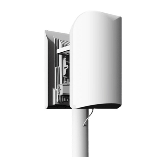
Figure 2-1 FW-300i Mounted on a Pole The BLiNQ FW-300i system is a tri-sector and tri-carrier Long-Term Evolution (LTE) Evolved Node B (eNB) with the capability to operate in the following bands: 42, 43, 46 and 48 (Citizens Broadband Radio Service (CBRS)). -
Page 10: Technical Features
Citizens Broadband Radio Service (CBRS) deployments. With each cell designed to operate as an independent Type B CBSD, the FW-300i can operate on a Priority Access or General Authorized Access basis in the CBRS band consistent with Title 47 CFR Part 96. -
Page 11: Figure 2-2 Fw-300I Sectors With Antenna Pattern
1 Sector Figure 2-3 Antenna Sectors with Examples of CA Mapping Multiple Input Multiple Output (MIMO): The FW-300i system features standard 2x2 MIMO configurations in both downlink (DL) and uplink (UL) directions for each active sector. High Modulation and Coding Scheme (MCS): The FW-300i hardware supports high MCS: ... -
Page 12: Network Management Features
FW-300i Web Interface (WebUI) — Accessible via HTTP(S), the FW-300i WebUI provides an interactive visual toolset that allows you to modify the full configuration of the FW-300i system, as well as view state, fault and performance indicators. The FW-300i WebUI displays performance data using visual charts and provides applications to visualize up to 24 hours of historical performance data stored on the system. - Page 13 SNMP traps or Syslog relays all alarms and events to higher level managers. The system also allows you to access active alarm and event history information using either the FW-300i CLI or WebUI. Performance Management — The FW-300i system maintains a comprehensive set of performance counters and indicators to facilitate: ...
-
Page 14: Fw-300I Security Protocols
(that is, the system modules retrieve the software package files from external FTP servers) or a push scheme using the FW-300i WebUI (that is, you upload a software package file to the system modules using the FW-300i WebUI). The FW-300i system also supports remote configuration backups and backup restoration. -
Page 15: Technical Specifications
BLiNQ Networks Inc. FW-300i User Manual Release 2.0 3 Technical Specifications This chapter covers: System Parameters, System Enclosure and Antenna Patterns. Confidential - Restricted Use and Duplication Issue 01... -
Page 16: System Parameters
BLiNQ Networks Inc. FW-300i User Manual Release 2.0 System Parameters Table 3-1 lists the FW-300i system parameters for the North American (NA) product line. Table 3-1 FW-300i System Parameters RADIO SPECIFICATIONS Frequency Band TDD LTE Bands: 42, 43, 48, 46... - Page 17 BLiNQ Networks Inc. FW-300i User Manual Release 2.0 ANTENNA SPECIFICATIONS CBRS BANDS 42/43 (48) (CONT.) Azimuth Sidelobe < -25 dB (Typ.) Front-to-Back Ratio @180 Degrees > 30 dB (Typ.) Co-Polar Port-to-Port Isolation 15 dB (Typ.) Cross-Polarization Port-to-Port Isolation > 20dB (Typ.) Max.
-
Page 18: System Enclosure
An integrated Global Positioning System (GPS) antenna is included in the FW-300i antenna, yet if needed, the FW-300i has a SYNC port, to use for example, as an optional external GPS Pulse per Second (PPS) source. Therefore, there is no need for additional synchronization equipment which reduces total cost of ownership. -
Page 19: Antenna Patterns
Antenna Patterns The FW-300i covers up to 180 degree of azimuth which is powered by an integrated adaptive antenna system of 3 x 60 degree sectors. Following are the antenna patterns for Band 42, 43, 48 and then by the antenna patterns for Band 46. -
Page 20: Getting Started With The Fw-300I
After successfully pinging the Craft IP address: Use a Secure Shell (SSH) client to log on to the FW-300i CLI using a SSH connection to the pinged 169.254.1.1 address. However, you must install SSH version 2.0 or higher client software on your host computer (you can use SSH version 1.0, but it is not recommended), or... -
Page 21: Fw-300I Web User Interface (Webui)
Release 2.0 FW-300i Web User Interface (WebUI) On initial log in to the FW-300i Web User Interface (WebUI), you see an overview of the FW-300i details; BLiNQ refers to these FW-300i details as the Dashboard. Figure 4-1, Welcome FW-300i Screen identifies the various elements of the FW-300i WebUI. - Page 22 BLiNQ Networks Inc. FW-300i User Manual Release 2.0 Alarms: Errors on your system will appear in this section, giving you the Alarm ID, Alarm Time, Component, Severity, Type, Probable Cause and Description of the error. LTE Cells Status: This is where you can monitor the LTE Cells’ operational parameters.
-
Page 23: Common Tools
Following are some common features of the FW-300i WebUI. 4.1.1.1 Title Bar: Tool Area Most FW-300i WebUI pages have either a Commit button or a Refresh button or both in the top right hand corner. Copy Running Configuration to Start-Up Configuration Button... -
Page 24: Minimized And Maximized Menus
Maximized Figure 4-3 View Maximized 4.1.1.3 System Information Bar The FW-300i system displays the model number, serial number, software version and current license (if applicable) status/number along the bottom of each main page. For example: 4.1.2 System Status Messages The FW-300i WebUI outputs the following types of real-time messages to report on the interaction... -
Page 25: Figure 4-5 Fw-300I Webui Warning Message
Warning message in yellow appears to explain the issue. You must click on a Warning message to dismiss it. They do not disappear automatically. Figure 4-5 FW-300i WebUI Warning Message Error Message (Red): ... -
Page 26: Default Fw-300I Configuration
BLiNQ Networks Inc. FW-300i User Manual Release 2.0 Default FW-300i Configuration The following table contains the FW-300i default configuration: Table 4-1 FW-300i Default Configuration Values CONFIGURATION DEFAULT SETTING DHCP Fixed, Non-routable Local Craft IP 169.254.1.1 Address Management IP Address Provided by DHCP... -
Page 27: Configuration
If you want to perform the configuration process using a CLI, see Section 5.3, “Configuration with the CLI”. Note: If you need more information on the FW-300i WebUI or CLI, consult the separate manual: “Complete WebUI and CLI Overview” The recommended FW-300i system commissioning process includes the following steps: ... -
Page 28: System Configuration Process
Release 2.0 System Configuration Process The FW-300i WebUI menu structure is the basis for the configuration process. This means that the configuration steps are set up so that you logically input all of the related parameters on a page before you move to the next page/step in the configuration process. -
Page 29: Configuration With The Webui
Configuration with the WebUI This section describes the tasks associated with preparing an FW-300i system to provide network services to its users using the FW-300i WebUI. If needed, see Figure 5-1, FW-300i Configuration Process for a visual overview of the configuration process. -
Page 30: Configuring A System Name
The eNodeB synchronizes using the Global Positioning System (GPS). When configured to synchronize via GPS, the FW-300i system uses its internal GPS antenna and receiver module to synchronize to the GPS network. This allows all network deployed FW-300i eNodeBs to... - Page 31 GPS source available. The FW-300i system includes a high performance crystal oscillator that allows it to maintain its clock properties (Holdover) even if the primary clock reference (that is, GPS) is no longer available. The system provides a Holdover period of 5 minutes.
-
Page 32: Network Connectivity Parameters
5.2.1.3 Network Connectivity Parameters Once logged on to the FW-300i, you can change the IP address of the WAN interface under Network Connectivity. There are two possible methods of assigning IP address to the system. You can choose either: ... -
Page 33: Advanced Options
BLiNQ Networks Inc. FW-300i User Manual Release 2.0 The changes do not take effect until you reboot the system. Reboot the system by selecting the Reboot System button ( ) in the top right corner. 5.2.1.4 Advanced Options When you click on the Show Advanced button, more configurable fields (IPv6 and Advanced Network Connectivity) will appear. - Page 34 BLiNQ Networks Inc. FW-300i User Manual Release 2.0 3. Select Commit in the top right corner to save your changes. Notes: With the current SW release, the IPv4 address and IPv6 address are either both statically assigned, or both obtained through DHCP. This behavior will be modified in the future software release such that methods for obtaining IP addresses are independent of each other.
-
Page 35: Carriers
BLiNQ Networks Inc. FW-300i User Manual Release 2.0 Notes: At any time during configuration changes and before clicking the Commit button, use the Reset Advance button to return to the previous settings and/or to update the information on the screen. -
Page 36: Set Cells 0-2 Rf Parameters
) button to cancel and return to the previous settings. Notes: The EARFCN or RF frequency parameter must match between an FW-300i and the CPE to create a link. 5.2.2.2 Set Cells 0-2 RF Parameters This is where you can set the parameters that are unique for each cell: 1. -
Page 37: Figure 5-2 Fw-300I Sectors
As a reference as to how the sectors are labelled, see Figure 5-2, “FW-300i Sectors”. Figure 5-2 FW-300i Sectors As seen in Figure 5-2 FW-300i Sectors”, the cells can be programmed to transmit out of different antenna sectors. A typical use for this is carrier aggregation, where for 2CC, two cells typically transmit out of the same sector antenna (Please refer to the latest software release notes to see if carrier aggregation is supported). - Page 38 55940 (Cell 2) Note: The FW-300i and CPE MUST have matching EARFCN or frequencies (that are within the range of usable frequency for the FW-300i system) to create a link. 4. The Carrier TX Power (Carrier Transmit Power) has a 29dBm maximum. Unless otherwise required, BLiNQ recommends that you keep the value unchanged.*...
-
Page 39: Advance Option
As a result of this feature, you are able to configure the FW-300i to cover 60 degrees (3 x 20MHz), 120 degrees (2 x 20MHz) or 180 degrees (1 x 20MHz). Please note that the max. Carrier Transmit Power will vary based on your configuration. -
Page 40: Lte Baseline
Band 48 overlaps with Band 42 and 43 (3550-3700MHz). The Multiband feature allows CPE that do not support Band 48 to connect to the FW-300i operating on Band 48. (ie. Backwards compatibility) To enable this feature, make sure that the “Enable Multiband” is turned to “YES”. -
Page 41: Configuring Lte Baseline Parameters
1. Navigate to the Setup > LTE Baseline page of the FW-300i WebUI 2. In the LTE Baseline Parameters section, enter a value between 0-6 for the Subframe Assignment field. As a default, it has the value of 2. - Page 42 Refer to Appendix B, “PCI Planning Guidelines” for more information on creating a PCI assignment strategy To enter PCI Seed Value: Navigate to the Setup > LTE Baseline Parameters page of the FW-300i WebUI. Confidential - Restricted Use and Duplication Issue 01...
- Page 43 Configuring the cell range parameter automatically sets the parameters that the CPE requires to establish the link. To assign the cell range: Navigate to the Setup > LTE Baseline page of the FW-300i WebUI. Confidential - Restricted Use and Duplication Issue 01...
- Page 44 BLiNQ Networks Inc. FW-300i User Manual Release 2.0 In the LTE Baseline Parameters section, set the Cell range to the desired kilometer range. The range is from 1 to 100 kilometers. 2km is the default value. Select Commit in the top right corner to save the changes on this page or select the Refresh ( button to cancel and return to the previous settings.
-
Page 45: Enb Identifiers
EPC Settings The Evolved Packet Core (EPC) sets up the optional integrated (embedded) Evolved Packet Core on the FW-300i system. In the EPC Settings section, you will configure the system to use either Embedded EPC or External EPC. This is also the section where you configure the PLMN ID. -
Page 46: Advanced Options
6. Select Commit in the top right corner to save your changes or select the Refresh ( ) button to cancel and return to the previous settings Note: EPC Provisioning - You use the CLI for setting up the optional embedded EPC on the FW-300i system. See Section 5.3.4, “EPC”. 5.2.3.4... - Page 47 Care must be taken when modifying this parameter. Please note that a value of -65 dBm configured on the FW-300i translates to a min. threshold of -130 dBm (ie. Multiplied by 2). If the CPE measures the signal strength lower than -130 dBm, then it will not attempt to connect.
- Page 48 BLiNQ Networks Inc. FW-300i User Manual Release 2.0 4. Select Commit in the top right corner to save your changes or select the Reset Advanced button to cancel and return to the previous advanced settings. 5.2.3.4.2 Setting Up RACH/PRACH Values Setting up the right values for RACH is critical to achieve up link synchronization between UE and eNB.
-
Page 49: Cbsd
BLiNQ Networks Inc. FW-300i User Manual Release 2.0 5. Once you are satisfied with your values, select Commit in the top right corner to save your changes or select the Reset Advanced button to cancel and return to the previous advanced settings. - Page 50 User ID: Input the CBSD User identification number FCC ID: Input the Federal Communications Commission (FCC) identification (ID) number. For FW-300i, the value is ROR00000005. SAS Server URL: Input the Spectrum Access System (SAS) database server Universal Resource Locator (URL), for example: https://testexample.com...
-
Page 51: Management
) in the top right corner. 5.2.5 Management The following sections only deal with using the FW-300i WebUI. If you want to use the CLI, see Section 5.3.6, “Management via the CLI”. 5.2.5.1 SSH/Web Users You configure the user name, password and access level for the local security of each unit. The SSH/Web Users feature allows you to add, modify (update password and read/write privileges level) or delete system users from the FW-300i WebUI. - Page 52 BLiNQ Networks Inc. FW-300i User Manual Release 2.0 To add users to (or modify an existing user on) the system using the FW-300i WebUI: Navigate to the Setup > Management > Web, CLI, Logging page of the FW-300i WebUI.
- Page 53 FW-300i User Manual Release 2.0 You can edit existing FW-300i users by selecting the hyperlinked name of the user you want to modify. The Update User dialog box appears. To reset a password, type in the new password and select the Update User button to confirm the new password.
-
Page 54: Syslog
5.2.5.2 Syslog The syslog interface allows the FW-300i system to send standard syslog fault management information (that is, syslog alarms, events and log entries) to external syslog servers. On the Setup > Management > Web, CLI, Logging page, you can set or change their operational status. -
Page 55: Snmp
BLiNQ Networks Inc. FW-300i User Manual Release 2.0 Navigate to the Management > Web, CLI, Logging page. From the Logging section, uncheck the box next to the syslog server that you want to delete. Select the Commit button at the top of the screen to save your changes. - Page 56 BLiNQ Networks Inc. FW-300i User Manual Release 2.0 To add an SNMP user: select the Add User button under the SNMP Users section. An Add User dialog appears. Input the name of the user in the Name field. Use the Access option to designate the user access level by selecting either the Read Only or Read Write option.
- Page 57 BLiNQ Networks Inc. FW-300i User Manual Release 2.0 Select the Add User button to add your user or the Cancel button to abandon the addition. If you need to edit an existing user, select the hyperlinked name of the desired user, an Update User dialog appears.
- Page 58 BLiNQ Networks Inc. FW-300i User Manual Release 2.0 5.2.5.3.2 Add or Remove SNMP Host To add or remove an SNMP host: Access the Management > SNMP; SNMP Hosts area. To add an SNMP host: select the Add Server button. An Add Server dialog appears. You need to know the Name, IP Address and Port for your SNMP host.
- Page 59 BLiNQ Networks Inc. FW-300i User Manual Release 2.0 Priv Password — sets the privacy encryption password; only visible when Security Level set to Authentication Privacy. Select the Add Server button to add your server or the Cancel button to abandon this addition.
-
Page 60: Verify, Save And Activate Current Running Configuration
Verify the currently running configuration to ensure that it matches the expected configuration. For instance, check that the EARFCN or radio frequencies match on the FW-300i and CPE. Select the Commit button at the top of the screen to save your changes. -
Page 61: Configuration With The Cli
Release 2.0 Configuration with the CLI This is a brief description on commands that you need to configure the FW-300i using a Command Line Interface (CLI). If desired, see Figure 5-1, FW-300i Configuration Process for a visual reference of the process. -
Page 62: Assigning Ip Address
Release 2.0 5.3.1.2 Assigning IP Address Once logged on to the FW-300i, you can change the IP address of the WAN interface. There are two methods. You can choose either: Static: statically assign the IP address for the WAN interface. If set to static: you must configure the IP address, netmask and default gateway (optional), or ... -
Page 63: Carriers
[radio rf x earfcn] OR [radio rf x frequency] where x is the desired radio number; repeat as required for each radio To create a radio link between an FW-300i and CPE, you must initially configure the channel bandwidth and frequency mode: ... -
Page 64: Enabling Cells
BLiNQ Networks Inc. FW-300i User Manual Release 2.0 Blinq eNB(config-rf-0)# top Blinq eNB(config)# radio rf 1 frequency 5150 Blinq eNB(config-rf-1)# top Blinq eNB(config)# radio rf 2 frequency 3550 Blinq eNB(config-rf-2)# commit Commit complete. Blinq eNB(config-rf-2)# end 5.3.2.2 Enabling Cells By default, the all 3 cells are disabled. Therefore, you will need to enable the cells prior to configuring them. -
Page 65: Lte Baseline
CLI Commands: [cell use-cell-range], [cell cell-range] To assign the cell range and set the maximum: Using the FW-300i CLI, enter the following commands: Blinq eNB# config Entering configuration mode terminal Blinq eNB(config)# cell use-cell-range true Blinq eNB(config)# cell cell-range 1 Blinq eNB(config)# commit Commit complete. -
Page 66: Assign An Enodeb Id
On the CLI, you use the cell enb-id to identify each cell when establishing a connection with the Evolved Packet Core (EPC). There are three connections per FW-300i. The system automatically generates three IDs from the configured value of this parameter for each cell respectively using the following logic: {[enb-id]*256}, {[enb-id]*256+1}, {[enb-id]*256+2}. -
Page 67: Epc Provisioning
Blinq eNB(config)# 5.3.4.2 EPC Provisioning You use the CLI for setting up the optional integrated Evolved Packet Core (EPC) on the FW-300i system. The FW-300i handles two forms of EPC: Embedded – internal, most of the settings are automatic ... -
Page 68: Embedded Epc
Both packages can only be uploaded to the FW-300i via FTP, so there is a pre-requisite to have a FTP server (with these packages) which is accessible from the FW-300i The FW-300i CLI commands required to install the Embedded EPC are as follows: ... - Page 69 BLiNQ Networks Inc. FW-300i User Manual Release 2.0 5.3.4.3.2 Configuration Embedded EPC can currently only be configured via the command line interface (CLI). Notes: You only need to submit the commit command after you have input all of your pre-configuration changes, however, to ensure that you do not forget to save your changes, you may enter the commit command after each configuration step.
- Page 70 The K, OPc and AMF parameters form the security keys which are used for authenticating the user when the CPE attempts to connect with the FW-300i. These values may be unique for each SIM cards. Please contact BLiNQ Networks Support to obtain this information.
-
Page 71: External Epc
BLiNQ Networks Inc. FW-300i User Manual Release 2.0 AMBR parameters (ambr-apn-dl, ambr-apn-ul, ambr-dl, ambr-ul) define the maximum instantaneous UL and DL throughout limits for the particular subscriber APN name defined for a specific user should match the definition in Section 2.1 and the configuration on the CPE. - Page 72 BLiNQ Networks Inc. FW-300i User Manual Release 2.0 5.3.4.4.4 Configure Default Bearer Configuring the HLR default bearer includes the following subscriber identity and Quality of Service (QoS) Profiles information: Subscriber Identity Module (SIM) card ID (International Mobile Subscriber Identity (IMSI)), ...
- Page 73 BLiNQ Networks Inc. FW-300i User Manual Release 2.0 5.3.4.4.7 Delete Default/Dedicated Bearer Use the following command to delete a default/dedicated bearer: CLI Command: [upd hlr imsi=<imsi> epsinfoded1] An example of the bearer delete command: RAN> upd hlr imsi=001015432100040 epsinfoded1 5.3.4.4.8...
- Page 74 You must configure the Mobility Management Entity (MME) to define the Public Land Mobile Network (PLMN) identifier (PLMN Id). The PLMN Id must match the configuration on the FW-300i. This command also includes a Tracking Area Identifier List (TAI List).
-
Page 75: Cbsd
5.3.4.4.13 Configure eNodeB Settings The command “add enodeb” requires a parameter in the format of <PLMN>-<eNB Id>. Note: You need to enter three (3) eNB IDs for each FW-300i and the eNB ID should equal: (value-in- FW-300i)*256, (value-in-FW-300i)*256+1, (value-in-FW-300i)*256+2. This setting defines the PLMN-eNodeB ID to establish the connection between FW-300i and EPC. -
Page 76: Management Via The Cli
Reboot the system to see and activate all of your configuration settings. Blinq eNB# system reboot 5.3.6 Management via the CLI You perform the following procedures via a CLI. If you wish to use the FW-300i WebUI, see Section 5.2.5, “Management”. Confidential - Restricted Use and Duplication Issue 01... -
Page 77: User
You configure the user name, password and access level for local security of each unit. Each unit’s configuration database stores the user configuration data on the FW-300i. To add users to the FW-300i system using the FW-300i CLI, enter these commands (<text> denotes the unique per user information that you must add/choose):... -
Page 78: Snmp
BLiNQ Networks Inc. FW-300i User Manual Release 2.0 Possible completions: User name [A-Za-z_][A-Za-z0-9_-]* admin range Test Blinq eNB(config)# no admin users user Test Blinq eNB(config)# admin users user ? This line doesn't have a valid range expression Possible completions: User name [A-Za-z_][A-Za-z0-9_-]*... -
Page 79: Syslog Server
This option is available in a future software release. This section deals with setting up syslog servers via the CLI. The syslog interface allows the FW-300i system to send standard syslog fault management information (that is, syslog alarms, events and log entries) to external syslog servers. - Page 80 BLiNQ Networks Inc. FW-300i User Manual Release 2.0 The mgmt syslog configuration command deals with remote syslog server and module log location configuration. 5.3.6.3.1 Add Syslog Server The mgmt syslog server command supports configuration of remote syslog servers. You can configure up to 5 remote syslog servers.
-
Page 81: Verify, Save And Activate Current Running Configuration
BLiNQ Networks Inc. FW-300i User Manual Release 2.0 5.3.7 Verify, Save and Activate Current Running Configuration Before exiting from the configuration system setup: Enable sector and radio transmitters Verify that the currently running configuration meets all of the pre-configuration system setup requirements. - Page 82 BLiNQ Networks Inc. FW-300i User Manual Release 2.0 cell enb-id 120 cell sector 0 rflist rf0 true cell-id cell-enabled true cell-group-id 30 q-rx-rev-min p-max-value cell sector 1 rflist rf1 true cell-id cell-enabled true cell-group-id 30 rnti cell-offset 1 q-rx-rev-min p-max-value...
-
Page 83: System Synchronization
Optional IEEE 1588v2 with Sync E. When configured to synchronize via GPS, the FW-300i system uses its internal GPS antenna and receiver module to synchronize to the GPS network. This allows all network deployed FW-300i eNodeBs to accurately synchronize their transmit and receive operations on the air interface. The GPS system also allows the FW-300i system to determine accurate time of day and date information. - Page 84 BLiNQ Networks Inc. FW-300i User Manual Release 2.0 sync-source System synchronization source (requires reset) Blinq eNB(config)# system sync sync-source ? Description: System synchronization source (requires reset) Possible completions: [gps] ptp-synce Blinq eNB(config)# system sync sync-source gps Blinq eNB(config)# commit Commit complete...
-
Page 85: Operation And Maintenance
Fault management via the Events: Alarms page Events history Note: If you need more information on the FW-300i WebUI or CLI, consult the separate manual: “Complete WebUI and CLI Overview” Confidential - Restricted Use and Duplication Issue 01... -
Page 86: Operation And Maintenance With The Webui
To perform system software upgrade activities, you must have read-write privileges to access this functionality. Following are the instructions for upgrading the system software via the FW-300i WebUI. The read-only Software Details area informs you of the device’s currently running software (active), the available standby software and the current upgrade status. - Page 87 BLiNQ Networks Inc. FW-300i User Manual Release 2.0 Within the Run Software Upgrade area, from the Software Upgrade Method, select either FTP Server or SFTP Server and enter the details (Host Address (IPv4 or IPv6), Username, Password and File Path).
- Page 88 Notes: You can only upgrade the FW-300i system software from one active browser session. This means you can not open another browser session and start another upgrade process in parallel with the first. If you try this, you get a warning message and the system does not let you continue.
-
Page 89: Performance
The eNodeB Statistics or eNB stats page is a read-only page that displays accumulated eNB throughput statistics for how the FW-300i and the associated sectors have been performing for the past 24 hours. The FW-300i stores a maximum of 96 performance history files over 24 hours before overwriting—one file for every 15 minutes of performance data. -
Page 90: Trace Log Files
BLiNQ Networks Inc. FW-300i User Manual Release 2.0 The CPE Statistics covers: CPE Id: identifies the CPE Sector: signifies the sector RNTI: denotes the Radio Network Temporary Identifier (RNTI) of a connected UE DL Tput: shows the downlink (DL) throughput (Tput) ... - Page 91 BLiNQ Networks Inc. FW-300i User Manual Release 2.0 To obtain a trace file: Navigate to the Performance > CPE Statistics > Trace column; then select the Start button under the desired CPE, this activates the trace file. The button label changes to say Stop and the button background changes from blue to red.
-
Page 92: Measurements
BLiNQ Networks Inc. FW-300i User Manual Release 2.0 6.1.2.4 Measurements Sector x Measurements page, where x represents the sector number, covers Key Performance Indicators (KPI) subcategories: accessibility, retainability, availability and mobility measurements for that sector. Part 1 of Sector 0 Measurements page Part 2 of Sector 0 Measurements page 6.1.2.4.1... - Page 93 BLiNQ Networks Inc. FW-300i User Manual Release 2.0 RRC.ConnEstabAtt.Cause: shows established RRC connections attempts per cause RRC.ConnEstabSucc.Cause: demonstrates successful RRC connections established per cause RRC Reestablishments per Cause: details Radio Resource Control (RRC) re-established connections per cause ...
-
Page 94: Events
BLiNQ Networks Inc. FW-300i User Manual Release 2.0 6.1.3 Events The system events are broken down into two sections: Alarms and History 6.1.3.1 Alarms (Logs) Page This read-only page lists active alarms (set alarms). Once you clear the Alarm, it appears on the Alarm and History pages along with its details. -
Page 95: History Page
Last button. Note: Clicking Clear History completely clears the current alarms and events history from the FW-300i event logging infrastructure. Use the Refresh button to update the information on the screen. -
Page 96: Operation And Maintenance With The Cli
FW-300i User Manual Release 2.0 Operation and Maintenance with the CLI The following sections deal with using the FW-300i CLI only. If you want to use the WebUI, see Section 6.1, “Operation and Maintenance with the WebUI”. 6.2.1 Software Upgrade Following are the instructions for upgrading the system software via the FW-300i CLI. -
Page 97: Performance
Release 1.1.1 transformer...ok. Configuration data migration succeeded. Proceeding with switchover. On completion, the FW-300i resets and you are forced out of the FW-300i CLI. Log in again once the FW-300i system is back up and running. If the software upgrade fails (due typically to a corrupt load), the output from the systems software download command indicates the upgrade was unsuccessful, and the system restarts again using the old software image. -
Page 98: Cpe Statistics
This performance read-only information visualizes the incoming and outgoing traffic for the interface connections between the CPE and the FW-300i. This allows you to see traffic and bandwidth usage for the interfaces in real-time and monitor the current download/upload throughput speeds. It also lists the current throughput performance statistics for the interfaces. -
Page 99: Trace Log Files
BLiNQ Networks Inc. FW-300i User Manual Release 2.0 With a specific CPE Blinq eNB# show pm cpe-stats cpe 285 PUSCH PUCCH DL UL RNTI SINR SINR SINR STATE DL TPUT UL TPUT TRACE ----------------------------------------------------------------------------------------------- 26.0 14.0 24.0 28 23... - Page 100 BLiNQ Networks Inc. FW-300i User Manual Release 2.0 CONN ESTAB CAUSE SUCC -------------- CONN REESTAB CAUSE ---------------- CONN REESTAB CAUSE SUCC ---------------- ERAB ESTAB INIT ------------ [...OUTPUT REMOVED FOR SPACE, otherwise 15 pages showing ALL measurements] Confidential - Restricted Use and Duplication...
- Page 101 BLiNQ Networks Inc. FW-300i User Manual Release 2.0 6.2.2.4.1 Accessibility ERAB Establishments per QCI — details the number of established attempts of E-UTRAN Radio Access Bearers (E-RAB) per Quality of Service (QoS) Class Identifier (QCI) erab-estab-add-att-nbr-list — shows the number of additional established attempts E-RAB per ...
- Page 102 BLiNQ Networks Inc. FW-300i User Manual Release 2.0 Blinq eNB# 6.2.2.4.2 Retainability ERAB Releases per QCI — details the number of E-UTRAN Radio Access Bearer (E-RAB) releases per Quality of Service (QoS) Class Identifier (QCI) plus the active session time ...
- Page 103 BLiNQ Networks Inc. FW-300i User Manual Release 2.0 ERAB ----------- Blinq eNB# 6.2.2.4.3 Availability rru-cell-unavailable-time-list — provides the percentage of time that the remote radio unit (RRU) is unavailable per cause (0 and 1) Example: Blinq eNB# show pm measurements 0 availability rru-cell-unavailable-time-list...
-
Page 104: Events
Blinq eNB# 6.2.3 Events Via the CLI, the FW-300i presents a table of the last 1000 events generated on the node. In the CLI, you use the “show” command to view the events. Each event contains the following information: ... - Page 105 BLiNQ Networks Inc. FW-300i User Manual Release 2.0 probable-cause — The probable cause of the event. severity — The severity of the event (info, warning, minor, major, critical). timestamp — The timestamp from when the event was generated (Date/time string: YYYY-MM- DDThh:mm:ss[+|-]hh:mm).
- Page 106 BLiNQ Networks Inc. FW-300i User Manual Release 2.0 event-id 12003 category type operational-status probable-cause operating-mode severity info timestamp 2018-08-31T19:02:12-05:00 notification-id 52 comment-data "UE Detached" event-history event 57431 module-id 0c:a1:38:00:04:06 component-name "RNTI 2134" event-id 12002 category type operational-status probable-cause operating-mode severity...
-
Page 107: Troubleshooting
FW-300i sync Wrong RF channel number Verify the RF channel number configured on CPE to confirm that it matches to FW-300i APN misconfiguration Verify the APN configured on CPE is the same as in the CPE profile on EPC... -
Page 108: Customer Premise Equipment (Cpe)
BLiNQ Networks offers a wide variety of CPEs, designed to meet your needs. Please contact BLiNQ for more information. You can also use a third party CPE to connect to the FW-300i. If so, please consult your third party CPE manual for details on this equipment or the relevant CPE Configuration Manual. -
Page 109: Appendix Ablinq Wireless Devices And Rf Safety/Les Appareils Sans Fil Blinq Et La Sécurité Rf
To prevent unnecessary exposure to RF energy: Always install the FW-300i system so as to provide and maintain a minimum separation distance of at least 1.1 metre from all persons. When the FW-300i system is operational, avoid standing directly in front of the FW-300i antennas. - Page 110 When the FW-300i system is operational, maintain a distance of at least 1.1 metre (43.3 inches) from the FW-300i antennas. Do not install the FW-300i system in a location where it is possible for people to stand or walk inadvertently in front of an antenna. Antenna Statement: The antenna used for this transmitter must be installed to provide a separation distance of at least 1.1...
-
Page 111: Equipment Compliance
BLiNQ Networks Inc. FW-300i User Manual Release 2.0 Equipment Compliance A.1.1 Federal Communications Commission (FCC) Notices This equipment has been tested and found to comply with the limits for a Class B digital device, pursuant to Part 15 of the FCC Rules. These limits are designed to provide reasonable protection against harmful interference in a residential installation. -
Page 112: Appendix Bpci Planning Guidelines
Cell ID (PCI) collision and enforce an effective PCI assignment strategy: Rule 1: Same PCI Utilization Multiple cells within a FW-300i on the same frequency should not have the same PCI Immediate neighbour cells on the same frequency should not have the same PCI Rule 2: PCI MOD3 ... - Page 113 BLiNQ Networks Inc. FW-300i User Manual Release 2.0 Rule 6: Cell Group ID Correlation Cell Group ID is derived from two length-31 binary m-sequences (m0, m1) Each time m0/m1 repeats, the overall correlation between the two Cell Group ID values is higher ...
-
Page 114: Appendix C Alarms And Events (Fault Management)
This appendix lists the alarms and events for the BLiNQ FW-300i system. Note: There is no need to open the FW-300i module casing. If there is an unsolvable problem or a module malfunction, please contact our Customer Service Department for help or a return merchandise authorization (RMA) number/procedure. - Page 115 1588 mode, the 1588 client has lost communication with the 1588 master clock. Upon FW-300i reset, this alarm is not raised until 60 s after reset and if synchronization still is not achieved. After holdover time expires (5 minutes), system transitions to unsynchronized state.
- Page 116 Sync E Unreliable The provider of SyncE connected to the Comms. CRITICAL FW-300i is either malfunctioning or not configured to provide SyncE on the FW-300i connection port. 7010 DHCP Server Unavailable The system has not been able to obtain a Comms.
-
Page 117: Table C-2 List Of Events
BLiNQ Networks Inc. FW-300i User Manual Release 2.0 Table C-2 List of Events NAME DESCRIPTION/COMMENTS TYPE SEVERITY Configuration Changed A configuration change has been committed System Information 2001 to the running configuration. Software Download Downloading software image. System Information 3001 Software Download Successful download of software image. -
Page 118: Appendix D List Of Acronyms
BLiNQ Networks Inc. FW-300i User Manual Release 2.0 Appendix D List of Acronyms ACRONYM MEANING Three Component Carriers 3GPP Third Generation Partnership Project Authentication, Authorization and Accounting (centralized networking protocol) Active Antenna System Acknowledgment Advanced Encryption Standard Assured Forwarding behavior, DSCP... - Page 119 BLiNQ Networks Inc. FW-300i User Manual Release 2.0 ACRONYM MEANING Committed Information Rate Command Line Interface Customer Premise Equipment Certified Professional Installer CPIR-ID Certified Professional Installer Registration Identification Channel Quality Indicator Craft IP IP address typically used by technical personnel to test the equipment...
- Page 120 BLiNQ Networks Inc. FW-300i User Manual Release 2.0 ACRONYM MEANING HARQ Hybrid Automatic Repeat reQuest High Density Home Location Register Handover HTTP Hyper Text Transfer Protocol HTTPS Hyper Text Transfer Protocol Secure ICIC Inter-Cell Interference Coordination IEEE Institute of Electrical and Electronics Engineers...
- Page 121 BLiNQ Networks Inc. FW-300i User Manual Release 2.0 ACRONYM MEANING Network Operations Mode Operations, Administration and Maintenance OLLA Outer Loop Link Adaptation Operations Support System PBCH Physical Broadcast Channel PCCH Paging Control Channel (PCCH) PCFICH Physical Control Format Indicator Channel...
- Page 122 BLiNQ Networks Inc. FW-300i User Manual Release 2.0 ACRONYM MEANING RSRP Reference Signal Received Power Received Target Power Received second Interface between an eNB and the Core Network (CN) Spectrum Access System Shared Channel SCTP Stream Control Transmission Protocol SeGW...
- Page 123 BLiNQ Networks Inc. FW-300i User Manual Release 2.0 ACRONYM MEANING UDP/IP User Datagram/Internet Protocol User Equipment uint16 Unsigned 16-bit integer with specified range, if any Uint32 Unsigned 32-bit integer with specified range, if any uint8 Unsigned 8-bit integer with specified range, if any...
- Page 124 BLiNQ Networks Inc. FW-300i User Manual Release 2.0 © Copyright 2012-2019 BLiNQ Networks Inc. All rights reserved. CONFIDENTIAL INFORMATION RESTRICTED USE AND DUPLICATION The information contained herein is the property of BLiNQ Networks Inc. and is strictly confidential. Except as expressly authorized in writing by BLiNQ Networks Inc., the holder shall keep all information contained herein confidential, shall disclose...
Need help?
Do you have a question about the FW-300i and is the answer not in the manual?
Questions and answers