Table of Contents
Advertisement
Cutler-Hammer
I.B. 69C3067H06
Instructions for the Use, Operation and Maintenance of
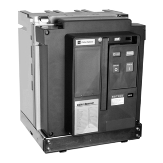
Types VCP-T and VCP-TR Vacuum Circuit Breakers
VCP-TR Fixed
(with or without trip unit - non-automatic shown)
VCP-T Drawout
(with or without trip unit - shown with Digitrip Trip Unit)
Effective February 2003 Supersedes I.B. 69C3067H05 dated March 2002
Courtesy of NationalSwitchgear.com
Advertisement
Table of Contents
Troubleshooting

Related Manuals for Cutler-Hammer VCP-TR Series


Summary of Contents for Cutler-Hammer VCP-TR Series
- Page 1 Cutler-Hammer I.B. 69C3067H06 Instructions for the Use, Operation and Maintenance of Types VCP-T and VCP-TR Vacuum Circuit Breakers VCP-TR Fixed (with or without trip unit - non-automatic shown) VCP-T Drawout (with or without trip unit - shown with Digitrip Trip Unit) Effective February 2003 Supersedes I.B.
- Page 2 Courtesy of NationalSwitchgear.com...
- Page 3 All possible contingencies which may arise during installation, operation or maintenance, and all details and variations of this equipment do no purport to be covered by these instructions. If further information is desired by purchaser regarding his particular installation, operation or maintenance of particular equipment, contact a Cutler-Hammer representative. Effective 2/03 Courtesy of NationalSwitchgear.com...
-
Page 4: Table Of Contents
I.B. 69C3067H06 Page iv TABLE OF CONTENTS Page SECTION 1: INTRODUCTION VCP-T and VCP-TR Vacuum Circuit Breaker Ratings............................1 Types VCP-T and VCP-TR Outlines and Dimensions ............................2 SECTION 2: SAFE PRACTICES SECTION 3: RECEIVING, HANDLING AND STORAGE Receiving ........................................11 Handling ........................................11 3-2.1 Unpacking ....................................11 3-2.2... - Page 5 I.B. 69C3067H06 Page v Vacuum Interrupter Integrity Test..................................47 Contact Erosion......................................49 Contact Wipe.........................................49 Insulation ........................................51 Insulation Integrity Check....................................51 Primary Circuit Resistance Check ................................51 Mechanism Check ......................................51 6-10 Lubrication ........................................51 6-11 Troubleshooting ......................................51 SECTION 7: RENEWAL PARTS General ........................................56 Ordering Instructions.....................................56 Mechanism and Related Parts ..................................57 Current Path........................................58 Electrical Attachments....................................59 Other Breaker Related Parts..................................62...
- Page 6 I.B. 69C3067H06 Page vi 4-16 Cradle Mounted Levering Mechanism ..............................27 4-17 Levering Circuit Breaker ...................................27 4-18 Circuit Breaker Connected as Indicated by Fully Connected Position Label ..................27 4-19 Circuit Breaker Shown in CONNECT Position with Secondary Connections Made .................28 4-20 Primary Safety Shutters Shown in Open Position with Fixed Primary Stabs Exposed..............28 4-21 Padlocking Device on Side of Cassette ............................28...
-
Page 7: Section 1: Introduction
I.B. 69C3067H06 Page 1 SECTION 1: INTRODUCTION The circuit breaker's nameplate provides complete rat- ing information. Reliable control and protection for medi- um voltage equipment and circuits are achieved through The purpose of this book is to provide instructions for the use of VCP-T and VCP-TR Vacuum Breakers. -
Page 8: Types Vcp-T And Vcp-Tr Outlines And Dimensions
I.B. 69C3067H06 Page 2 1-2 Types VCP-T and VCP-TR Outlines and Dimensions (Circuit Breakers and Drawout Cassettes) Figure 1-1 VCP-TR Fixed Breaker 4.76/8.25kV, 600A/800A, 16kA, 60kV BIL Only Outlines in inches [mm] Effective 2/03 Courtesy of NationalSwitchgear.com... -
Page 9: All Vcp-Tr Fixed (Except 4.76/8.25Kv, 600/800A, 16Ka, 60Kv Bil See Figure 1-1) Outlines
I.B. 69C3067H06 Page 3 Figure 1-2 All VCP-TR Fixed (except 4.76/8.25kV, 600/800A, 16kA, 60kV BIL see Figure 1-1) Outlines in inches [mm] Effective 2/03 Courtesy of NationalSwitchgear.com... -
Page 10: Vcp-T Drawout Breaker 4.76/8.25Kv Outlines Outlines
I.B. 69C3067H06 Page 4 Figure 1-3 VCP-T Drawout Breaker 4.76/8.25kV Outlines in inches [mm] (Refer to above Applicable Ratings Table) Effective 2/03 Courtesy of NationalSwitchgear.com... -
Page 11: Vcp-T Drawout Breaker 4.76/8.25Kv Outlines
I.B. 69C3067H06 Page 5 Figure 1-4 VCP-T Drawout Breaker 4.76/8.25kV Outlines in inches [mm] (Refer to above Applicable Ratings Table) Effective 2/03 Courtesy of NationalSwitchgear.com... -
Page 12: Vcp-T Drawout Breaker 8.25/15Kv Outlines
I.B. 69C3067H06 Page 6 Figure 1-5 VCP-T Drawout Breaker 8.25/15kV Outlines in inches [mm] (Refer to above Applicable Ratings Table) Effective 2/03 Courtesy of NationalSwitchgear.com... -
Page 13: Vcp-T Breaker Cassette Up To 95Kv Bil Outlines
I.B. 69C3067H06 Page 7 Figure 1-6 VCP-T Breaker Cassette Up to 95kV BIL Outlines in inches [mm] (Additional Details Figures 1-7 &1-8) Effective 2/03 Courtesy of NationalSwitchgear.com... -
Page 14: Vcp-T Breaker Cassette 60Kv Bil Outlines
I.B. 69C3067H06 Page 8 Figure 1-7 VCP-T Breaker Cassette 60kV BIL Outlines in inches [mm] (Additional Details Figure 1-6) Effective 2/03 Courtesy of NationalSwitchgear.com... -
Page 15: Vcp-T Breaker Cassette 60 & 95Kv Bil Outlines
I.B. 69C3067H06 Page 9 Figure 1-8 VCP-T Breaker Cassette 95kV BIL Outlines in inches [mm] (Additional Details Figure 1-6) Effective 2/03 Courtesy of NationalSwitchgear.com... -
Page 16: Section 2: Safe Practices
I.B. 69C3067H06 Page 10 SECTION 2: SAFE PRACTICES ing to death, severe personal injury and/or property damage. The circuit breakers are equipped with high speed, high • Always make sure that primary and secondary energy operating mechanisms. They are designed with power are disconnected from a fixed breaker before built-in safety interlocks to provide for safe operation. -
Page 17: Section 3: Receiving, Handling And Storage
Record any observed damage for reporting to 3-2.2 LIFTING the transportation carrier and Cutler-Hammer. All reports should be as specific as possible and include To closely examine, install or just become familiar with... -
Page 18: Storage
MADE WITH RESPECT TO THE ANSI GUIDELINES OR INTENT. 75 VCP-TR20 1200 75 VCP-T20 UNDER NO CIRCUMSTANCES SHOULD ALTER- 1600 ATIONS BE MADE TO CUTLER-HAMMER SUPPLIED 75 VCP-TR25 VCP-T VCP-TR CIRCUIT BREAKERS UNLESS THE 1200 ALTERATION IS SPECIFICALLY ADDRESSED IN 75 VCP-T25 1600 AND PERMITTED BY THIS INSTRUCTION BOOK. -
Page 19: Front And Rear Views Vcp-Tr Fixed (4.76 And 8.25Kv, 600/800A, 16Ka, 60Kv Bil)
I.B. 69C3067H06 Page 13 Secondary Disconnect with Protective Hood Vacuum Interrupter Primary Conductor Interface Drive Insulator with Internal Contact Loading Spring (Wipe Spring) Vacuum Interrupter Movable Stem Rear Customer Mounting Holes Customer Ground (Earth) Connection Integral Lifting Hook Pole Unit Molding 11 Gauge Grounded (Earth) Steel Barrier Front Cover (Figure 3-9 for details) Trip Unit Location (Non-Automatic... -
Page 20: Front And Rear Views All Vcp-Tr Fixed (Except 4.76 And 8.25Kv, 600/800A, 16Ka, See Figure 3-3)
I.B. 69C3067H06 Page 14 Secondary Disconnect with Protective Hood Vacuum Interrupter Primary Conductor Interface Drive Insulator with Internal Contact Loading Spring (Wipe Spring) Vacuum Interrupter Movable Stem Rear Customer Mounting Holes Customer Ground (Earth) Connection Horizontal Phase Barrier (95kV BIL Only) Vertical Phase Barrier (95kV BIL Only) Integral Lifting Hook Front Cover (Figure 3-9 for details) -
Page 21: Front And Rear Views Vcp-T Drawout (4.76 And 8.25Kv, 600/800A, 16Ka, 60Kv Bil)
I.B. 69C3067H06 Page 15 Vacuum Interrupter Primary Disconnect Finger Cluster Drive Insulator with Internal Contact Loading Spring (Wipe Spring) Vacuum Interrupter Movable Stem Cradle with Levering Mechanism Shoot Bolt Handle Shoot Bolt Push/Pull Handle Racking Screw Lock Plate Levering Drive Nut Integral Wheel Shutter Operator Integral Lifting Hook... -
Page 22: Front And Rear Views All Vcp-T Drawout (Except 4.76/8.25Kv, 630/800A, 16Ka, 60Kv Bil See Figure 3-5)
I.B. 69C3067H06 Page 16 Secondary Disconnect Protective Hood (Umbilical Cord not shown) Vacuum Interrupter Primary Disconnect Finger Cluster (1200A Cluster Shown) Drive Insulator with Internal Contact Loading Spring (Wipe Spring) Vacuum Interrupter Movable Stem Cradle with Levering Mechanism Shoot Bolt Handle Shoot Bolt Push/Pull Handle Racking Screw Lock Plate... -
Page 23: Front And Rear Views Drawout Cassette (For Use With 60Kv Bil Drawout Breakers Only)
I.B. 69C3067H06 Page 17 Breaker Position and Safety Shutter Padlocking Mechanism Primary Connection Pad Primary Insulating Tube (Spout) Safety Shutter Operating Arm Secondary Umbilical Cord Connector Anti-tilt Channel Customer Earth (Ground) Connection Automatic Primary Safety Shutters (Closed Position) Cradle Stop/Hook Stop Mounting Holes Rejection Interlock Pins Interlock Lever (Secondary Contact) -
Page 24: Front And Rear Views Drawout Cassette (For Use With All 95Kv Bil Drawout Breakers)
I.B. 69C3067H06 Page 18 Anti-tilt Channel Breaker Position and Safety Shutter Padlocking Mechanism Primary Connection Pad Primary Insulating Tube (Spout) Safety Shutter Operating Arm Secondary Umbilical Cord Connector Customer Earth (Ground) Connection Automatic Primary Safety Shutters (Closed Position) Cradle Stop/Hook Stop Mounting Holes Rejection Interlock Pins Interlock Lever (Secondary Contact) -
Page 25: Typical Vcp-T
I.B. 69C3067H06 Page 19 (Red) CLOSED (Green) OPEN (Yellow) CHARGED (White) DISCHARGED (Green) PUSH ON PUSH OFF (Red) Trip Unit (Optional) Accessory Window (3) Rating Plug Contact Status (Open-Close) Trip Unit Test Port Spring Status (Charged-Discharged) Trip Unit Cover with Two Mounting Manual “OFF”... -
Page 26: Section 4: Installation And Wiring
I.B. 69C3067H06 Page 20 SECTION 4: INSTALLATION AND WIRING the barriers used with specific breakers. Any other barriers required to meet ANSI requirements must be supplied by the customer. They must be constructed of an appropriate NOTICE insulating material, such as thick high strength, track resis- tant glassmat polyester or polycarbonate of appropriate thickness. -
Page 27: Installing Drawout Circuit Breaker
If they are not compatible, do not attempt to insert the circuit breaker into the cassette. Rejection Interlocks Contact Cutler-Hammer for assistance if required. Rejection interlocks are steel pins mounted at the bottom of Table 4.1 Cassette Rejection Interlock Pin Locations... -
Page 28: 4-6.2 Circuit Breaker Positioning
I.B. 69C3067H06 Page 22 operated permitting them to be locked in the closed posi- NOTE: Rejection tion for safety when the breaker is disconnected or pin nuts located on removed.or the open position for servicing the fixed primary bottom side of the tray should be disconnects. -
Page 29: Positioning Circuit Breaker With Lifter
I.B. 69C3067H06 Page 23 Shoot Bolt Shoot Bolt Figure 4-5 Breaker Shoot Bolts Against Cassette Figure 4-4 Positioning Circuit Breaker With Lifter The shoot bolt handle as shown in Figure 4-6 has three labeled positions NOTICE Position “A” - Full down position causing the shoot bolts to retract fully inside the breaker cradle (not A number of labels have been applied to the circuit engaged) -
Page 30: 4-6.3 Drawout Electrical Interfaces
I.B. 69C3067H06 Page 24 The circuit breaker and cassette are designed such that NECT position. The shoot bolt handle must, however, be the lower portion of the circuit breaker (the cradle) is held in in Position “C” (fully engaged) to be the TEST position and the DISCONNECT/TEST position by two shoot bolts which before the circuit breaker can be levered to the CONNECT- fit into the rectangular slots of interlock plates located on... -
Page 31: Circuit Breaker Umbilical Cord Shown Connected To Breaker Prior To Breaker Insertion
I.B. 69C3067H06 Page 25 Protective Hood Mounting Screw Mounting Screw Figure 4-11 Secondary Connector Viewed From Rear of Breaker secondary connector at Location “1” on the top front Figure 4-10 Secondary Umbilical Cord Shown underside of the cassette (Figure 4-12). Make certain Connected to Breaker Prior to Breaker Insertion that the connector on the umbilical cord is completely inserted into the cassette’s connector. -
Page 32: 4-6.4 Levering Circuit Breaker
I.B. 69C3067H06 Page 26 6 Fixed Primary Stabs Inside Insulating Spouts Correct For Circuit Racking Screw Breaker Positioning Lock Plate Figure 4-14 Circuit Breaker Shown in Levered Out DIS- CONNECT Position - Correct for Breaker Positioning Figure 4-13 Drawout Cassette with Primary Safety Shutters Open Showing Fixed Primary Stabs back of the cassette (Figures 3-5, 3-6 and 4-13). -
Page 33: Cradle Mounted Levering Mechanism
I.B. 69C3067H06 Page 27 Once the VCP-T circuit breaker is in the TEST position with the secondary umbilical cord properly connected, it is ready to be levered into the CONNECTED position. Using a deep (1 inch/25 mm) socket and levering crank, engage the large drive nut on the front of the breaker cradle. -
Page 34: Circuit Breaker Shown In Connect Position With Secondary Connections Made
I.B. 69C3067H06 Page 28 Figure 4-20 Primary Safety Shutters Shown in Open Position with Fixed Primary Stabs Exposed Figure 4-19 Circuit Breaker Shown in CONNECT Position with Secondary Connections Made During the levering process, the metallic primary safety shutters in the cassette automatically move out of the way exposing the fixed cassette stabs, thus permitting the cir- cuit breaker to make its primary connection (Figure 4-20). -
Page 35: Section 5: Description And Operation
I.B. 69C3067H06 Page 29 The circuit breakers utilize a rigid frame construction of SECTION 5: DESCRIPTION AND OPERATION engineered thermoset composite resins with a patented pole unit molding. In addition to high strength structural 5-1 INTRODUCTION properties, the material used has excellent dielectric char- acteristics and resists tracking (Figure 5-1). -
Page 36: Vcp-Tr Fixed Non-Automatic Circuit Breaker (Front Cover Removed)
I.B. 69C3067H06 Page 30 Secondary Wiring Manual “OFF” Pushbutton Through-The-Window Accessories Manual “ON” Pushbutton Electric Charging Motor Operations Counter Manual Charging Handle 5A/5B Auxiliary Switch Contact Status (Open-Close) Opening Spring Spring Status (Charged-Discharged) OFF Key Lock Location Motor Cutoff Switch Trip Unit Location Figure 5-2 VCP-TR Fixed Non-Automatic Circuit Breaker (Front Cover Removed) Effective 2/03... -
Page 37: Vcp-T Drawout Circuit Breaker (Front Cover Removed)
I.B. 69C3067H06 Page 31 Secondary Wiring Opening Spring Through-The-Window Accessories OFF Key Lock Location Electric Charging Motor Motor Cutoff Switch Manual Charging Handle Trip Unit (Optional) Contact Status (Open-Close) Cradle with Levering Mechanism Spring Status (Charged-Discharged) Shoot Bolt Handle Manual “OFF” Pushbutton Shoot Bolt Manual “ON”... -
Page 38: 5-2.1 Contact Erosion Indicator
A great deal of effort has been spent in the design of all Cutler-Hammer vacuum circuit breakers, in order to eliminate the need for field adjustments of wipe or stroke. Refer to paragraph 6-7 for details on visually inspecting contact wipe. -
Page 39: Stored Energy Mechanism
I.B. 69C3067H06 Page 33 5-3 STORED ENERGY MECHANISM 5-3.1 MANUAL OPERATION A standard circuit breaker is a manually operated breaker WARNING with one shunt trip. The closing springs can only be charged manually. To manually charge the springs, insert one finger in the recess behind the charging handle and KEEP HANDS AND FINGERS AWAY FROM THE pull out. -
Page 40: 5-3.2 Electrical Operation
I.B. 69C3067H06 Page 34 5-3.2 ELECTRICAL OPERATION For electrically operated circuit breakers, the springs are normally charged through the use of a rugged electrical motor operator (Figure 5-7). The springs can, however, be manually charged as just described in the previous section. -
Page 41: Connection Diagrams
I.B. 69C3067H06 Page 35 with no more than two wires per terminal. Two male type secondary plug-in connectors are mounted on the top rear portion of the circuit breaker. The plug-in con- nectors are protected by a molded hood (Figure 5-14). When the front cover of the circuit breaker is removed, the top of each plug-in connector is exposed. -
Page 42: Vcp-T And Vcp-Tr Non Trip Unit Connection Diagram
I.B. 69C3067H06 Page 36 NOTES 1. THE “SR” DEVICE HAS ADDITIONAL CIRCUITRY THAT PROVIDES A 0.2 SECOND SIGNAL PULSE FOR CLOSING OPERATION POWER MUST BE REMOVED AND THEN REAPPLIED FOR A SUBSEQUENT OPERATION. 2. THE “LCS” ACTS AS A “LOGIC” INPUT TO THE “SR” DEVICE. THE CLOSE SIGNAL PULSE WILL NOT BE SENT UNTIL THE BREAKER IS RESET. 3. -
Page 43: Vcp-T And Vcp-Tr With 520V Trip Unit Connection Diagram
I.B. 69C3067H06 Page 37 Figure 5-11 VCP-T and VCP-TR with 520V Trip Unit Connection Diagram Effective 2/03 Courtesy of NationalSwitchgear.com... -
Page 44: Vcp-T And Vcp-Tr With 1150V Trip Unit Connection Diagram
I.B. 69C3067H06 Page 38 Figure 5-12 VCP-T and VCP-TR with 1150V Trip Unit Connection Diagram Effective 2/03 Courtesy of NationalSwitchgear.com... -
Page 45: Vcp-T Drawout Umbilical Cord And Connector Wiring Diagram
I.B. 69C3067H06 Page 39 ‘A’ BLOCK BREAKER SIDE ‘A’ BLOCK UMBILICAL CASSETTE SIDE CUSTOMER CONNECTION ‘B’ BLOCK BREAKER SIDE ‘B’ BLOCK UMBILICAL CASSETTE SIDE CUSTOMER CONNECTION Figure 5-13 VCP-T Drawout Umbilical Cord and Connector Wiring Diagram Effective 2/03 Courtesy of NationalSwitchgear.com... -
Page 46: Top View Secondary Connectors
I.B. 69C3067H06 Page 40 Secondary Connectors Legend Auxiliary Switch MOTOR Charging Motor Spring Charge Indicator Spring Release Shunt Trip S/T2 Shunt Trip 2 Undervoltage Release Figure 5-15 Top View Secondary Connectors Hinged Covers Figure 5-16 Secondary Male Connector with Female Figure 5-17 Optional Terminal Block Pins Figure 5-18 AMP Secondary Wiring Removal Tool... -
Page 47: Electronic Tripping System
Table 5.1. The two models (Model 520V and Model 1150V) are not interchangeable in the field. A functional local test can be performed through the trip Contact Cutler-Hammer for upgrading to Model 520V or unit’s test receptacle (Figure 5-19). A small hand held Model 1150V. -
Page 48: 5-5.2 Rating Plug
I.B. 69C3067H06 Page 42 5-5.2 RATING PLUG Neutral current sensors are available for customer installation. The additional sensor is not supplied with All trip units use a fixed type rating plug. The current the circuit breaker and must be ordered separately. rating of the rating plug must match the current rating of They are wired to the trip unit through the secondary the current sensors (Figure 5-19 and Table 5.2). -
Page 49: Accessory Devices
I.B. 69C3067H06 Page 43 5-6 ACCESSORY DEVICES A variety of accessory devices are available for use with VCP-T and VCP-TR circuit breakers. Unless otherwise stated, they should be considered optional devices in the sense that they are not provided as standard on a manually operated circuit breaker. -
Page 50: 5-6.2 Internal Electrical Accessories
I.B. 69C3067H06 Page 44 Table 5.4 Spring Release Ratings Table 5.3 Shunt Trip Ratings Control Operational Inrush Power Typical Control Operational Inrush Power Typical Voltages Voltage Range Consumption OpeningTime Voltages Voltage Range Consumption Closing Time 24 Vdc 17-26 250 VA 25 - 38 ms 24 Vdc 20-27... -
Page 51: Rugged Motor Operator
I.B. 69C3067H06 Page 45 Figure 5-26 Auxiliary Switch Figure 5-25 Rugged Motor Operator Kit Table 5.6 Motor Operator Ratings Control Operational Running Inrush Power Charging Voltages Voltage Range Current Current Consumption Time 24 Vdc 20-27 8 Amperes 400% of Running 250 VA 5 sec 48 Vdc... -
Page 52: 5-6.3 Mechanical Accessories
I.B. 69C3067H06 Page 46 5-6.3 MECHANICAL ACCESSORIES is interconnected with either cables or rods, depending upon the relative orientation of the breakers. Rods can There are six mechanical type accessories: be used only when the circuit breakers to be interlocked are vertically stacked. -
Page 53: Section 6: Inspection And Maintenance
I.B. 69C3067H06 Page 47 SECTION 6: INSPECTION AND MAINTENANCE is imperative that an establised schedule be followed. To establish an exact schedule for a specific installation, use the following guidelines: 6-1 INTRODUCTION 1. In a clean, non-corrosive environment, inspect and WARNING maintain each breaker every 2000 operations or 3 years, whichever comes first. -
Page 54: Inspection And Maintenance Procedures
I.B. 69C3067H06 Page 48 Table 6.1 Inspection and Maintenance Procedures Effective 2/03 Courtesy of NationalSwitchgear.com... -
Page 55: Contact Erosion
I.B. 69C3067H06 Page 49 shall be as shown in Table 6.2. WARNING Table 6.2 Test Voltage Breaker Rated APPLYING ABNORMALLY HIGH VOLTAGE ACROSS Vacuum Interrupter Integrity Test Voltage A PAIR OF OPEN CONTACTS IN VACUUM MAY PRO- Maximum Voltage at 60 Hz DUCE X-RADIATION. -
Page 56: Contact Erosion Mark Visible On Stem
I.B. 69C3067H06 Page 50 Inspection Inspection Area Area Drive Drive Insulator Insulator Figure 6-2 Contact Wipe Inspection Area Figure 6-1 Contact Erosion Mark Visible on Stem Top Surface Top Surface Drive Insulator Drive Insulator Wipe Indicator Wipe Indicator Flush with Top Below Top Surface Surface Figure 6-4 Unsatisfactory Contact Wipe Condition with... -
Page 57: Insulation
If the problem cannot be resolved with the aid of this guide, 6-8 PRIMARY CIRCUIT RESISTANCE CHECK contact the Cutler-Hammer service center for more in- depth assistance. Since the main contacts are inside the vacuum cham- ber, they remain clean and require no maintenance at any time. -
Page 58: Troubleshooting Guide
Trip latch is defective Inspect latch condition and engagement before closing; con- sult Cutler-Hammer service center Circuit breaker cannot be opened Shunt trip control signal absent or Check supply voltage exceeds remotely, but can be opened locally... - Page 59 I.B. 69C3067H06 Page 53 Table 6.4 Troubleshooting Guide (continued from previous page) Symptom Probable Cause Corrective Actions Circuit breaker cannot be closed Spring release (closing) coil supply Check power supply voltage; remotely (can be closed locally) voltage low or spring release faulty replace spring release if faulty Secondary contact wiring problem Make sure electrical pin and sock-...
-
Page 60: Circuit Breaker Lubrication
I.B. 69C3067H06 Page 54 MAGNA-LUBE USE 10W30 OIL ON BOTH MOLDED SURFACES AND STEEL BEARING SURFACES ALONG BREAKER LAYSHAFT (8 LOCATIONS TOTAL) USE 10W30 OIL ON BEARINGS AND MAGNA-LUBE ON THREADS OF JACK SCREW (ENTIRE LENGTH OF JACK SCREW USE 10W30 OIL ON MAIN PIVOT OF POLE SHAFT (BEAR- ING SURFACES) INDICATED HERE ON BOTH SIDES Figure 6-5 Circuit Breaker Lubrication Effective 2/03... -
Page 61: Drawout Cassette Lubrication
I.B. 69C3067H06 Page 55 MAGNA-LUBE FULL LENGTH OF GROUNDING (EARTHING) BAR SPAR- INGLY BOTH SIDES AS SHOWN SHOWN MAGNA-LUBE TOP UNDERSIDE OF ANTI- TILT CHANNELS SHOWN HERE ALONG ENTIRE SURFACE USE 10W30 OIL INSIDE OF ROLLER AND MAGNA-LUBE OUTSIDE OF ROLLER USE 10W30 OIL INSIDE FLANGE OF DRIVE PLATE BEARING BOTH SIDES OF CASSETTE... -
Page 62: Section 7: Renewal Parts
Describe the item, give the style number, and specify the quantity required. c. Specify the voltage for electrical components. d. Specify the method of shipping desired. e. Send all orders or correspondence to the nearest Cutler-Hammer sales office. Effective 2/03 Courtesy of NationalSwitchgear.com... -
Page 63: Mechanism And Related Parts
HARDWARE INCLUDED Description Cat# Mechanical Counter MCOUNT Lock Type Lock Required* Key Required* Style# Ronis 1104A Protec 67A3140G01 Castell CL1019 CL1062 67A3140G02 Kirk CN22-104-1B92890 67A3140G03 * Cutler-Hammer does not supply Lock or Key, only the provision Effective 2/03 Courtesy of NationalSwitchgear.com... -
Page 64: Current Path
Black Opening Spring (Low Energy) 67A3142G01 Blue Opening Spring (High Energy) 67A3142G02 Shock Absorber All Breakers 67A3143G01 (7) Faceplate, Buttons and Flags Requires C-HESS (Cutler-Hammer Engineering Services and Systems) Installation HARDWARE INCLUDED Description Style# Faceplate, Buttons and Flags 2A10895G01 7-4 CURRENT PATH... -
Page 65: Electrical Attachments
I.B. 69C3067H06 Page 59 7-5 ELECTRICAL ATTACHMENTS (3) Undervoltage Release Customer Field Installable (1) Shunt Trip (Opening Coil) Customer Field Installable NOTE: For an optional shunt trip capability, both a shunt trip and a shunt trip switch must be ordered and used. - Page 66 I.B. 69C3067H06 Page 60 6) Auxiliary Switch 9) Breaker Secondary Disconnect Block Customer Field Installable Customer Field Installable HARDWARE INCLUDED Style# Description 67A3147G01 5a/5b Double Break Type Additional items available from manufacturer: Socket for 14-18 AWG. wire (AMP #66598-2) Socket for 18-26 AWG. wire (AMP #641300-2) Socket Crimper Tool (AMP #90067-4) HARDWARE INCLUDED Removal Tool (AMP #305183)
- Page 67 I.B. 69C3067H06 Page 61 12) Secondary Terminal Block Kit 14) Secondary Umbilical Cord Customer Field Installable Customer Field Installable Description Style# 15 (6 point) Terminal Blocks and Labels 1B93092G01 Description Style# 13) Secondary Terminal Wire Kit Customer Field Installable Secondary Umbilical Cord 69C3323G01 (Drawout Circuit Breakers Only) 15) Simple Ground and Test Device...
-
Page 68: Other Breaker Related Parts
I.B. 69C3067H06 Page 62 7-6 OTHER BREAKER RELATED PARTS (3) Door Escutcheon and Gasket Customer Field Installable (1) Phase Barriers Customer Field Installable Left Barrier Escutcheon Right Barrier (door frame) Gasket Horizontal Barriers (One Set) Inside Vertical Barriers (One Set) Outside Vertical Barriers (One Set) -
Page 69: Trip Unit And Related Parts
(1) 1150V Trip Unit Kit (Trip Unit and Power Supply) Description Style# Requires C-HESS (Cutler-Hammer Engineering Services and Systems) Installation Spout Boot Kit includes required boots, fins and wire 69C3320G01 ties sufficient for 6 spouts (6 boots, 6 fins and 18... - Page 70 Courtesy of NationalSwitchgear.com...
- Page 71 ING OR USAGE OF TRADE, ARE MADE REGARDING THE INFORMATION, RECOMMENDATIONS AND DESCRIPTIONS CONTAINED HEREIN. In no event will Cutler-Hammer be responsible to the purchaser or user in contract, in tort (including negligence), strict lia- bility or otherwise for any special, indirect, incidental or...
Need help?
Do you have a question about the VCP-TR Series and is the answer not in the manual?
Questions and answers