Table of Contents
Advertisement
Quick Links
Cutler-Hammer
Instructions for Operation and Maintenance
of Digitrip OPTIM Trip Units
P
R
O
T
P
O
W
E
R
Q
U
A
L
I
T
Y
C
O
M
Effective 11/98 Supersedes I.B. 29C891A dated October 1996
E
C
T
I
O
N
Series C K, L, N and R Molded Case Circuit Breakers
SPB Systems Pow-R Circuit Breakers
DSII/DSLII Power Circuit Breakers
M
U
N
I
C
A
A
N
D
C
O
O
T
I
O
N
S
R
D
I
N
A
T
I
S
Y
S
T
E
I.B. 29C891B
O
N
E
N
E
R
G
Y
M
O
N
I
T
O
R
I
N
G
M
S
Advertisement
Table of Contents

Related Manuals for Cutler-Hammer Digitrip OPTIM 550


Summary of Contents for Cutler-Hammer Digitrip OPTIM 550
- Page 1 Cutler-Hammer I.B. 29C891B Instructions for Operation and Maintenance of Digitrip OPTIM Trip Units Series C K, L, N and R Molded Case Circuit Breakers SPB Systems Pow-R Circuit Breakers DSII/DSLII Power Circuit Breakers Effective 11/98 Supersedes I.B. 29C891A dated October 1996...
- Page 2 TRADE, ARE MADE REGARDING THE INFORMATION, RECOMMENDATIONS AND DESCRIPTIONS CON- TAINED HEREIN. In no event will Cutler-Hammer be responsible to the purchaser or user in contract, in tort (includ- ing negligence), strict liability or otherwise for any special, indirect, incidental or consequential damage or loss what-...
-
Page 3: Table Of Contents
I.B. 29C891B Page iv TABLE OF CONTENTS Page SECTION 1: INTRODUCTION Common Terms..............................1 Preliminary Comments and Safety Precautions....................1 1-2.1 Safety Precautions ..........................1 Product Overview ..............................2 Features and Functions............................5 1-4.1 Common Features of Digitrip OPTIM 750 and 1050 Trip Units..............5 1-4.2 Additional Features of Digitrip OPTIM 1050 Trip Units ................7 SECTION 2: HARDWARE DESCRIPTION AND EQUIPMENT INTERFACES... - Page 4 I.B. 29C891B Page v Page SECTION 4: STARTUP AND TESTING Introduction................................40 Wiring ................................40 4-2.1 Wiring Diagrams ...........................40 4-2.2 Wiring Plan Drawing ..........................40 4-2.3 Network Wiring Diagram ........................40 Initial Startup ..............................40 4-3.1 Before Power Application ........................40 4-3.2 Initial Power Application ........................41 Testing................................41 SECTION 5: TROUBLESHOOTING AND MAINTENANCE...
- Page 5 I.B. 29C891B Page vi LIST OF FIGURES Figure Title Page Series C L-Frame Molded Case Circuit Breaker with OPTIM Trip Unit .............2 SPB Systems Pow-R Circuit Breaker with OPTIM Trip Unit..............2 DSII Power Circuit Breaker with OPTIM Trip Unit ..................2 Family of Digitrip OPTIM Trip Unit Rating Plugs..................3 Family of Digitrip Trip Units Comparison ....................3 Hand Held Programmer in Use........................4...
- Page 6 OPTIM Trip Unit Metering Tolerances .....................19 Digitrip OPTIM 750 and 1050 Trip Unit Capabilities ................20 Digitrip OPTIM 550 Trip Unit System Capabilities Overview ..............22 Digitrip OPTIM 750 Trip Unit System Capabilities Overview ..............23 Digitrip OPTIM 1050 Trip Unit System Capabilities Overview ..............24 Troubleshooting Guide ..........................43...
-
Page 8: Common Terms
If further information is required by the purchaser throughout this manual. They are defined here to elimi- regarding a particular installation, application or mainte- nate any confusion that might arise when reading the nance activity, a Cutler-Hammer representative should text. be contacted. IMPACC (Integrated Monitoring, Protection and Control Communications) –... -
Page 9: Product Overview
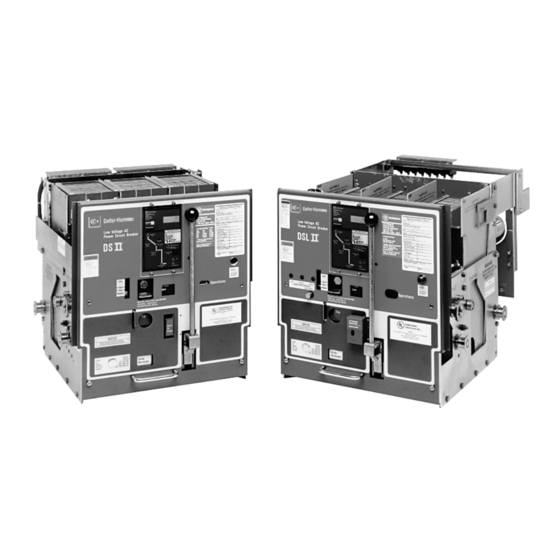
I.B. 29C891B Page 2 1-3 PRODUCT OVERVIEW The Digitrip OPTIM Trip Unit is a programmable, com- municating, microprocessor-based, low voltage trip unit. Digitrip OPTIM Trip Units are for use with Series C K- Frame, L-Frame, N-Frame and R-Frame Molded Case Circuit Breakers, SPB Systems Pow-R Circuit Breakers, and DSII/DSLII Power Circuit Breakers (Figures 1-1, 1-2 and 1-3). -
Page 10: Family Of Digitrip Optim Trip Unit Rating Plugs
I.B. 29C891B Page 3 Refer to paragraph 1-4 for feature and function details. A Digitrip OPTIM Trip Unit System can be tailored to meet very precise system requirements. The featured parts of an OPTIM Trip Unit System are: • OPTIM 550, 750 or OPTIM 1050 Trip Unit •... -
Page 11: Hand Held Programmer In Use
I.B. 29C891B Page 4 Figure 1-7 Breaker Interface Module in Service Figure 1-6 Hand Held Programmer in Use Module, and the optional IMPACC software form a sys- Integrated Assembly Applications (Low Voltage tem that is capable of: Assemblies) • Setting trip units These applications are utilized to provide on-gear or remote monitoring and even testing of compatible •... -
Page 12: Features And Functions
For additional IMPACC details, refer to Section 3 of Instruction Book 29C890. 1-4 FEATURES AND FUNCTIONS Digitrip OPTIM 550, 750 and 1050 Trip Units provide a wide range of common protection and coordination fea- tures and functions. The Digitrip OPTIM 1050 Trip Unit also provides power quality and energy monitoring capa- bilities. -
Page 13: Typical System Configurations
I.B. 29C891B Page 6 Master Computer CONFIGURATION 2 Master Computer and IMPACC Software Shielded Twisted Pair To Other IMPACC Compatible Devices PONI Module (Required for IMPACC CONFIGURATIONS 1 + 2 Network Communications to Master Computer) PONI Network Configuration — Breaker Interface Module with Master Computer as Master Device Breaker... -
Page 14: 1-4.2 Additional Features Of Digitrip Optim 1050 Trip Units
I.B. 29C891B Page 7 Communications 1-4.2 ADDITIONAL FEATURES OF DIGITRIP OPTIM 1050 TRIP UNITS Trip units that are capable of two way communication operate via a network twisted pair for remote monitoring The Digitrip OPTIM 1050 Trip Unit provides all the basic and control. -
Page 15: Hardware Description And Equipment Interfaces
I.B. 29C891B Page 8 SECTION 2: HARDWARE DESCRIPTION 2-2.1 TRIP UNIT CONFIGURATION AND EQUIPMENT INTERFACES A complete OPTIM Trip Unit System consists of current sensors, electronic circuitry and a flux transfer shunt trip 2-1 GENERAL device contained inside the circuit breaker (Figure 2-1). The trip units are completely self-contained and, when the The purpose of this section is to familiarize the reader circuit breaker is closed, no external power is required to... -
Page 16: Series C K, L-Frame And N-Frame Optim Trip Units
I.B. 29C891B Page 9 Models 750 and 1050 on K, L and N-Frame circuit and N-Frame circuit breakers. Model 550 does not breakers are factory sealed. Model 550 equipped circuit need the bracket on the same frames. breakers and all R-Frame SPB and DSII circuit breakers can be upgraded in the field. -
Page 17: Front View Of L-Frame Type Optim Trip Unit (K And N-Frame Designs Are Similar)
I.B. 29C891B Page 10 ➃ ➅ ➆ ➄ ➇ ➂ ➁ ➀ ➄ ➀ Unit Status LED Push-to-Trip Button ➁ ➅ INCOM Transmit LED (Model 550 requires field IMPACC kit) Mode of Trip/Alarm LEDs ➆ ➂ Battery Compartment/Pro-gramming Port Access Cover Battery Test Pushbutton/LED ➇... -
Page 18: Series C R-Frame, Spb And Dsii/Dslii Optim Trip Units
I.B. 29C891B Page 11 covering the OPTIMizer Hand Held Unit Status LED Programmer for the recommended connection The green Unit Status LED blinks with a one second on- and power application sequence. off duty cycle when power is applied to the trip unit and it is functioning properly. -
Page 19: 2-5.1 R-Frame, Spb And Dsii/Dslii Optim Trip Unit Displays
I.B. 29C891B Page 12 Push-To- Open Button Push-To-Trip Button Figure 2-8 OPTIM Trip Unit Mounted in SPB Circuit Figure 2-9 OPTIM Trip Unit Mounted in DSII Circuit Breaker Breaker vated. The LEDs are presented in the form of a mimic 2-5.1 R-FRAME, SPB AND DSII/DSLII OPTIM TRIP UNIT DISPLAYS time-current curve on the front of the OPTIM Trip Unit. -
Page 20: Front View Of R-Frame, Spb And Dsii/Dslii Type Optim Model 1050 Trip Unit With R-Frame Rating Plug Installed
I.B. 29C891B Page 13 ➀ ➃ Mode of Trip/Alarm LEDs ➁ Automatic Trip Indicator Reset Pushbutton ➂ Unit Status LED ➃ INCOM Transmit LED ➄ Programming Port ➅ Rating Plug (Hinged Cover Closed) ➅ ➄ ➀ ➁ ➂ Figure 2-10 Front View of R-Frame, SPB and DSII/DSLII Type OPTIM Model 1050 Trip Unit with R-Frame Rating Plug Installed Unit Status LED The green Unit Status LED blinks with a one second... -
Page 21: Optim Trip Unit Rating Plug
I.B. 29C891B Page 14 OPTIMizer Hand Held Programmer for the recommended connection and power applica- tion sequence. 2-6 OPTIM TRIP UNIT RATING PLUG The rating plug value (I ) determines the maximum con- tinuous current rating of the circuit breaker. All the pro- tection function settings are based on multiples of the plug rating. -
Page 22: External Optim Trip Unit Accessories
I.B. 29C891B Page 15 Control Power Source All rating plugs are designed with a rejection feature to prevent interchanging between different circuit breaker K, L, and N-Frame circuit breakers with OPTIM Model types. In addition, the circuit breaker will trip if a rating 750 or 1050 Trip Units utilize 24 Vdc control power from plug is removed with the trip unit energized. -
Page 23: Externally Mounted Potential Transformer Module (Necessary For K, L And N-Frame Only)
I.B. 29C891B Page 16 Figure 2-15 Externally Mounted Potential Transformer Figure 2-16 Ground Fault Alarm Indicator (necessary Module (necessary for K, L and N-Frame only) for K, L and N-Frame only) Effective 11/98... -
Page 24: Rating Plugs Applicable To All Optim Trip Units
I.B. 29C891B Page 17 Table 2.1 Rating Plugs Applicable to All OPTIM Trip Units Series C Series C Series C Series C SPB Systems DSII/DSLII K-Frame Breaker L-Frame Breaker N-Frame Breaker R-Frame Breaker Pow-R Breakers Breakers Rating Plug (I Frame Rating Rating Plug (I Frame Rating Rating Plug (I... -
Page 25: Optim Trip Unit/Accessory Specifications
I.B. 29C891B Page 18 Table 2.2 OPTIM Trip Unit/Accessory Specifications TRIP UNITS Potential Transformer Module (PTM) (Catalog DOPTMLN, Style 7801C54G01) Environment: • Input voltage terminals LA, LB and LC • Operating Temperature -20°C to 85°C • Rated input voltage 0 to 600 volts line to line •... -
Page 26: Optim Trip Unit Metering Tolerances
I.B. 29C891B Page 19 Table 2.3 OPTIM Trip Unit Metering Tolerances ➀ Parameter Circuit Breaker Type Accuracy Range/Assumptions Phase Current K, L, N ±2% Frame Current Rating 5% to 100% Frame Rating R, SPB ±2% Frame Current Rating 5% to 100% (Current) DSII, DSLII ±2% Sensor Current Rating Sensor Rating... -
Page 27: General
OPTIM Trip Unit accuracies are specified for each protective function (long delay, short delay instantaneous and ground fault) Table 3.1 Digitrip OPTIM 550, 750 and 1050 Trip Unit and the type of circuit breaker in which the trip unit is Capabilities installed. -
Page 28: Sample Of Partial Time-Current Trip Curve
I.B. 29C891B Page 21 Before discussing protection functions individually, keep in mind that combining functional capabilities, such as Pickup Setting long, short and instantaneous, is a coordination activity. The effects of one set of settings on another set should be carefully evaluated to determine if the results for all possible circumstances are acceptable. -
Page 29: Digitrip Optim 550 Trip Unit System Capabilities Overview
I.B. 29C891B Page 22 Table 3.2 Digitrip OPTIM 550 Trip Unit System Capabilities Overview TRIP UNIT TYPE DIGITRIP OPTIM 550 RMS Sensing Programmable CIRCUIT BREAKERS Types Series C K, L and N-Frames Series C R-Frames Ampere Range 70 - 1200A... -
Page 30: Digitrip Optim 750 Trip Unit System Capabilities Overview
I.B. 29C891B Page 23 Table 3.3 Digitrip OPTIM 750 Trip Unit System Capabilities Overview TRIP UNIT TYPE DIGITRIP OPTIM 750 RMS Sensing Programmable CIRCUIT BREAKERS Types Series C K, L and N-Frames»` Series C R-Frames SPB Pow-R DSII/DSLII Power Ampere Range 70 - 1200A 800 - 2500A 200 - 5000A... -
Page 31: Digitrip Optim 1050 Trip Unit System Capabilities Overview
I.B. 29C891B Page 24 Table 3.4 Digitrip OPTIM 1050 Trip Unit System Capabilities Overview TRIP UNIT TYPE DIGITRIP OPTIM 1050 RMS Sensing Programmable CIRCUIT BREAKERS Types Series C K, L and N-Frames»` Series C R-Frames SPB Pow-R DSII/DSLII Power Ampere Range 70 - 1200A 800 - 2500A 200 - 5000A... -
Page 32: 3-2.3 Protection And Curve Shaping Features
I.B. 29C891B Page 25 • If it is later determined that the Long Delay Setting (I and/or instantaneous protection. Modals 750 and 1050 is to be 140 amperes in lieu of the original 100 achieve LSI by turning off the “A” feature on the LSIA unit. amperes. -
Page 33: 3-2.4 Long Delay Protection
I.B. 29C891B Page 26 Note: Arrows indicate direction of curve OVERLOAD AND SHORT CIRCUIT movement 1. Long Delay Setting 2A. Long Delay Time I 2B. Long Delay Time I SHORT CIRCUIT 3. Short Delay Pickup 4A. Short Delay Time Flat Response 4B. -
Page 34: Typical Long Delay Setting Adjustment
I.B. 29C891B Page 27 Note: Long Delay Setting Note: Long Delay Time represented by Setting represented dotted lines by dotted lines CURRENT CURRENT Figure 3-6 Typical Long Delay Setting Adjustment Figure 3-7 Typical Long Delay Time Adjustment (I Response Long delay pickup, which is determined from the time- The long delay time setting is programmable to an I t or current curves, establishes the current level at which the... -
Page 35: 3-2.5 Short Delay Protection
I.B. 29C891B Page 28 Notice: Keep in mind during testing that a faster trip time instantaneous protection or without instantaneous pro- may be observed due to the cumulative Thermal tection. Either both, one or the other (short or instanta- Memory Effect (powered or unpowered). neous) must always be provided (Tables 3.2 and 3.3 and Figure 3-4). -
Page 36: Typical Short Delay Time Adjustment, Flat Response
I.B. 29C891B Page 29 Note: Short Delay Time Note: Short Delay Time Setting represented Setting represented by dotted lines by dotted lines CURRENT CURRENT Figure 3-10 Typical Short Delay Time Adjustment, Flat Figure 3-11 Typical Short Delay Time Adjustment, (I Response Response curve can be moved vertically and independently by... -
Page 37: 3-2.6 Instantaneous Protection
(I Appendix A for specific connection schemes. For more The programmable range depends on the circuit breaker detailed application information, contact Cutler-Hammer. type as follows: • Series C K, L and N-Frames 3-2.6 INSTANTANEOUS PROTECTION... -
Page 38: 3-2.7 Ground Fault Protection
I.B. 29C891B Page 31 Override (Fixed Instantaneous) An override (fixed instantaneous) circuit is included in all circuit breakers except DSII and DSLII circuit breakers. It protects against a short-circuit current that exceeds the Note: Instantaneous short-time withstand current capability of the circuit Pickup represented breaker. -
Page 39: Ground Fault Alarm Led
I.B. 29C891B Page 32 torially sums the outputs of the individual phase current sensors. As long as the vectorial sum is zero, no ground fault exists. If the system is 4-wire and a neutral conductor exists, it is necessary to use an additional sensor for the purpose of properly accounting for this neutral current in the ground fault scheme. -
Page 40: 3-2.8 Time-Current Curves
3-2.8 TIME-CURRENT CURVES The specific time-current curves applicable to all Digitrip OPTIM Trip Units are identified in Appendix A, Table A.1. Contact Cutler-Hammer for a specific curve. 3-3 SYSTEM MONITORING CURRENT Digitrip OPTIM Trip Units provide an electrical distribution... -
Page 41: 3-3.1 Displays And Led Indicators
I.B. 29C891B Page 34 metered parameters are monitored and then displayed • Minimum/Maximum magnitudes all monitored currents over the OPTIM information system. Local LEDs are used to indicate a number of conditions and/or operations. The Automatic Trip Condition LEDs are complemented by trip event information When a system condition results in an automatic trip, stored in non-volatile memory. -
Page 42: 3-3.4 Power And Energy Monitoring
I.B. 29C891B Page 35 CIRCUIT BREAKER FOR MAINTENANCE PERSON- utes before the first non-zero value is displayed. The NEL TO USE IN CONTROLLING REMOTE CLOSE OR peak demand value displayed remains and is not TRIP SIGNALS. changed until a higher peak demand is calculated in a subsequent 15 minute window. -
Page 43: 3-4.1 Impacc
I.B. 29C891B Page 36 ucts with remote personal computers into a comprehen- DE-ENERGIZE THE CIRCUIT, “REMOVE”, “DISCON- sive information and control communications network. NECT” OR MOVE THE CIRCUIT BREAKER TO AN The integral communications capability of OPTIM Trip APPROPRIATE “TEST” POSITION BEFORE PER- Units permits the receiving device to be the following: FORMING MAINTENANCE OR TESTS. -
Page 44: 3-5.1 Secondary Injection Testing
“TEST” OR “DISCONNECTED” CELL POSITION, OR WARNING WHILE REMOVED TO A TEST BENCH. Digitrip OPTIM 550, 750 and 1050 Trip Units have a test CIRCUIT BREAKER OPERATING MECHANISMS capability. “No-Trip” and “Trip” tests can be performed OPEN AND CLOSE THE MOVING PARTS QUICKLY using any of the following: AND WITH VERY HIGH ENERGY. -
Page 45: 3-5.4 Performance Testing For Ground Fault Trip Units
I.B. 29C891B Page 38 Keep in mind that the Trip Reset pushbutton located on the front of the trip unit will have to be pushed to reset trip unit conditions after a test is completed that causes the circuit breaker to trip and LED indicators to be lit (Figures 2-4 and 2-10). -
Page 46: Typical Performance Test Record Form
I.B. 29C891B Page 39 GROUND FAULT TEST RECORD FORM Ground Fault Test Record should be Retained by Those in Charge of the Building’s Electrical Installation in order to be available to the Authority having Jurisdiction. TEST DATE CIRCUIT BREAKER RESULTS NUMBER Figure 3-21 Typical Performance Test Record Form Effective 11/98... -
Page 47: Startup And Testing
I.B. 29C891B Page 40 SECTION 4: STARTUP AND TESTING 4-3.1 BEFORE POWER APPLICATION 4-1 INTRODUCTION WARNING This section addresses those procedures associated with the startup and testing of installed Digitrip OPTIM STARTUP PROCEDURES MUST BE PERFORMED Trip Units. As a minimum, the OPTIMizer Hand Held BY QUALIFIED PERSONNEL WHO ARE FAMILIAR Programmer Instruction Book 29C892 along with this WITH DIGITRIP OPTIM TRIP UNITS, THE LOW VOLT-... -
Page 48: 4-3.2 Initial Power Application
Digitrip OPTIM Trip Unit System, including Module instruction books (I.B. 29C892 and I.B. IMPACC communications. 29C893 respectively). For further assistance, consult Cutler-Hammer. 4-3.2 INITIAL POWER APPLICATION 4-4 TESTING a. Apply system power and observe individual trip units and/or other system monitoring devices, such as the Section 3-5 provides details associated with testing Breaker Interface Module or remote computer. -
Page 49: Typical Network Wiring Diagram
I.B. 29C891B Page 42 Master Computer ➀ For network interconnection cable, use Belden 9463 or Cutler-Hammer IMPCABLE. ➁ When interconnecting devices, tie Shielded shield drain wires together for shield Twisted Pair path continuity. To Other IMPACC ➂ Connect the shield path to a solid Compatible Devices earth ground at one point only. -
Page 50: Troubleshooting And Maintenance
Digitrip OPTIM Trip Unit, the device should be replaced. The malfunctioning Except for the rating plug and the battery for the local device may be returned to Cutler-Hammer for further indicator, the Digitrip OPTIM Trip Unit is designed to be evaluation. - Page 51 I.B. 29C891B Page 44 Table 5.1 Troubleshooting Guide (continued from previous page) Symptom Probable Cause Possible Solution(s) References Power values are grossly Connections from PT Module to Check connections Table A.1 in error (1050 Trip Units breaker not made or are incorrect. Wiring Diagrams only).
- Page 52 I.B. 29C891B Page 45 Table 5.1 Troubleshooting Guide (continued from previous page) Symptom Probable Cause Possible Solution(s) References Ground fault alarm unit Connections to ground fault alarm Check connections Table A.1 does not operate on a unit are incorrect. Wiring Diagrams ground fault.
- Page 53 I.B. 29C891B Page 46 Table 5.1 Troubleshooting Guide (continued from previous page) Symptom Probable Cause Possible Solution(s) References Trip unit may be the problem. Replace breaker. Refer to Note 1 at end of Para. 5-3 Table 5.1. Zone selective interlocking on ground fault and/or See directions for checking zone selective interlocking Appendix B...
- Page 54 I.B. 29C891B Page 47 Table 5.1 Troubleshooting Guide (continued from previous page) Symptom Probable Cause Possible Solution(s) References “Connection Failure” when OPTIMizer not working or cord not Verify OPTIMizer operation on another breaker. I.B. 29C892 OPTIMizer is plugged in. properly plugged into OPTIMizer. Para.
- Page 55 I.B. 29C891B Page 48 Table 5.1 Troubleshooting Guide (continued from previous page) Symptom Probable Cause Possible Solution(s) References Breaker trips too rapidly GOUT to GIN and/or SOUT to SIN Add connections Table A.1 on ground fault or short are not shorted. Wiring Diagrams delay (zone selective interlocking not used).
- Page 56 I.B. 29C891B Page 49 Table 5.1 Troubleshooting Guide (continued from previous page) Symptom Probable Cause Possible Solution(s) References Power values are grossly No voltage input to trip unit. Check PT disconnect plug is installed. in error. (1050 Trip Units only) Frequency incorrect Verify operating frequency with OPTIMizer.
- Page 57 I.B. 29C891B Page 50 Table 5.1 Troubleshooting Guide (continued from previous page) Symptom Probable Cause Possible Solution(s) References Breaker trips on ground There actually is a ground fault Find the location of the fault and remove it. N.A. fault. On four wire systems the neutral Check the connections at terminals at D6 and D7 Table A.1 current sensor may not have the...
- Page 58 I.B. 29C891B Page 51 Table 5.1 Troubleshooting Guide (continued from previous page) Symptom Probable Cause Possible Solution(s) References breakers. The transmit LED should flash when there is communication. With the external con- nections to C11 and C12 or C6 and C7 opened temporarily, the resistance “looking into”...
- Page 59 I.B. 29C891B Page 52 Table 5.1 Troubleshooting Guide (continued from previous page) Symptom Probable Cause Possible Solution(s) References straps on the four point ground fault terminal block on the RD and SPB breakers are con- nected D5 - D6 and D7 - D8. Trip unit may be the problem.
-
Page 60: 5-4.1 Local Indicator Battery Check And Replacement
I.B. 29C891B Page 53 Figure 5-1 Battery Test Pushbutton and LED Shown on Figure 5-2 Battery Test Pushbutton and LED Shown on Face of OPTIM Trip Unit OPTIM Rating Plug 5-4.1 LOCAL INDICATOR BATTERY CHECK AND type or equivalent 3 volt lithium battery. Refer to Table REPLACEMENT 2.2 for acceptable battery replacements. -
Page 61: 5-4.2 Rating Plug Replacement
I.B. 29C891B Page 54 Figure 5-3 Battery Shown Installed in Battery/Program- Figure 5-4 Battery Shown Installed Behind Rating Plug ming Port Compartment Hinged Cover 5-4.2 RATING PLUG REPLACEMENT Secure the rating plug in position by turning the positioning screw in the clockwise direction Notice: Mechanical rejection means will prevent the until it is snug. -
Page 62: Return Procedure
To have a Digitrip OPTIM Trip Unit returned, contact your local Cutler-Hammer authorized distributor. 5-6 TECHNICAL ASSISTANCE For information, technical assistance or referral to a local authorized distributor, contact the Customer Support Center at 1-800-356-1243. -
Page 63: Appendix A Instructional References
I.B. 29C891B Page 56 APPENDIX A - INSTRUCTIONAL REFERENCES A list of instructional references is provided in Table A.1 to identify instructional documents that could be of assis- tance. Table A.1 Instructional References (continued on next page) DOCUMENT DESCRIPTION DOCUMENT NUMBER Circuit Breakers Series C K-Frame Frame Book IL 29-120K... - Page 64 I.B. 29C891B Page 57 Table A.1 Instructional References (continued from previous page) DOCUMENT DESCRIPTION DOCUMENT NUMBER Accessories Potential Transformer Module (K, L and N-Frame) 29C126 Ground Fault Indicator 1259C14G01 Digitrip OPTIM Time-Current Curves Series C K-Frame Curves t Long & Short Delay Phase SC-6924-98 t Long &...
-
Page 65: Appendix B Checking Zone Selective Interlocking
I.B. 29C891B Page 58 APPENDIX B - CHECKING ZONE nations for the breaker terminals to which this voltage is to be applied are: SELECTIVE INTERLOCKING NEP/LEP Trip Units REP Trip Units (RD and SPB) (DSII) Notice: See wiring diagrams for specifications on wire size, number of permissible breakers and other + side of voltage SOUT... - Page 66 ING OR USAGE OF TRADE, ARE MADE REGARDING THE INFORMATION, RECOMMENDATIONS AND DESCRIPTIONS CONTAINED HEREIN. In no event will Cutler-Hammer be responsible to the purchaser or user in contract, in tort (including negligence), strict lia- bility or otherwise for any special, indirect, incidental or...
Need help?
Do you have a question about the Digitrip OPTIM 550 and is the answer not in the manual?
Questions and answers