Sign In
Upload
Manuals
Brands
Cutler-Hammer Manuals
Circuit breakers
75 VCP-TR25
Cutler-Hammer 75 VCP-TR25 Manuals
Manuals and User Guides for Cutler-Hammer 75 VCP-TR25. We have
1
Cutler-Hammer 75 VCP-TR25 manual available for free PDF download: Instructions For The Use, Operation And Maintenance
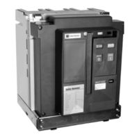
Cutler-Hammer 75 VCP-TR25 Instructions For The Use, Operation And Maintenance (71 pages)
Vacuum Circuit Breakers, Fixed with or without trip unit - non-automatic shown, Drawout with or without trip unit - shown with Digitrip Trip Unit
Brand:
Cutler-Hammer
| Category:
Circuit breakers
| Size: 13 MB
Table of Contents
Table of Contents
4
Table Title
7
Section 1: Introduction
7
VCP-T and VCP-TR Ratings
7
VCP-T and VCP-TR Vacuum Circuit Breaker Ratings
7
Figure Title
8
Types VCP-T and VCP-TR Outlines and Dimensions
8
VCP-TR Fixed Breaker 4.76/8.25Kv, 600A/800A, 16Ka, 60Kv BIL Only Outlines
8
All VCP-TR Fixed (Except 4.76/8.25Kv, 600/800A, 16Ka, 60Kv BIL See Figure 1-1) Outlines
9
VCP-T Drawout Breaker 4.76/8.25Kv Outlines Outlines
10
VCP-T Drawout Breaker 4.76/8.25Kv Outlines
11
VCP-T Drawout Breaker 8.25/15Kv Outlines
12
VCP-T Breaker Cassette up to 95Kv BIL Outlines
13
VCP-T Breaker Cassette 60Kv BIL Outlines
14
VCP-T Breaker Cassette 60 & 95Kv BIL Outlines
15
Section 2: Safe Practices
16
Section 3: Receiving, Handling and Storage
17
Receiving
17
Handling
17
3-2.1 Unpacking
17
3-2.2 Lifting
17
Fixed Breaker Shown Mounted on Pallet
17
Storage
18
Typical Breaker and Cassette Weights
18
Keyed Shipping Clamp Being Removed from Fixed Breaker
18
Circuit Breaker and Cassette Weights
18
Front and Rear Views VCP-TR Fixed (4.76 and 8.25Kv, 600/800A, 16Ka, 60Kv BIL)
19
Front and Rear Views All VCP-TR Fixed (Except 4.76 and 8.25Kv, 600/800A, 16Ka, See Figure 3-3)
20
Front and Rear Views VCP-T Drawout (4.76 and 8.25Kv, 600/800A, 16Ka, 60Kv BIL)
21
Front and Rear Views All VCP-T Drawout (Except 4.76/8.25Kv, 630/800A, 16Ka, 60Kv BIL See Figure 3-5)
22
Front and Rear Views Drawout Cassette (for Use with 60Kv BIL Drawout Breakers Only)
23
Front and Rear Views Drawout Cassette (for Use with All 95Kv BIL Drawout Breakers)
24
Typical VCP-T
25
Section 4: Installation and Wiring
26
Initial Inspection
26
Electrical Clearances
26
Interphase Barriers
26
Front Cover
26
Installing Fixed Circuit Breaker
26
4-5.1 Fixed Mechanical Interfaces
26
4-5.2 Fixed Electrical Interfaces
26
Installing Drawout Circuit Breaker
27
4-6.1 Drawout Mechanical Interfaces
27
Typical Fixed Non-Automatic VCP-TR 15KV Circuit Breaker
27
Bottom View of VCP-TR Circuit Breaker Showing Mounting Holes
27
Cassette Rejection Interlock Pin Locations
27
4-6.2 Circuit Breaker Positioning
28
Cassette Rejection Interlock Pin Positioning
28
Positioning Circuit Breaker with Lifter
29
Breaker Shoot Bolts against Cassette
29
Shoot Bolt Handle in up (Locked) Position
29
4-6.3 Drawout Electrical Interfaces
30
Shoot Bolt Handle Shown in Position "C" - Shoot Bolts Protrude Fully from Cradle
30
Shoot Bolt Handle Shown in Position "B" - Shoot Bolts Protrude Partially from Cradle
30
Shoot Bolt Handle Shown in Position "A" - Shoot Bolts Retracted Fully Inside Cradle
30
Circuit Breaker Umbilical Cord Shown Connected to Breaker Prior to Breaker Insertion
31
Secondary Connector Viewed from Rear of Breaker
31
Cassette Secondary Connector and Interlock Lever
31
4-6.4 Levering Circuit Breaker
32
Drawout Cassette with Primary Safety Shutters Open Showing Fixed Primary Stabs
32
Circuit Breaker Shown in Levered out (DISCONNECT) Position - Correct for Breaker Positioning
32
Circuit Breaker Shown in Levered in (CONNECT) Position - Incorrect for Breaker Positioning
32
Cradle Mounted Levering Mechanism
33
Levering Circuit Breaker
33
Circuit Breaker Connected as Indicated by Fully Connected Position Label
33
Circuit Breaker Shown in CONNECT Position with Secondary Connections Made
34
Primary Safety Shutters Shown in Open Position with Fixed Primary Stabs Exposed
34
Padlocking Device on Side of Cassette
34
Section 5: Description and Operation
35
Introduction
35
Vacuum Interrupter Assembly
35
Rigid Frame Construction
35
VCP-TR Fixed Non-Automatic Circuit Breaker (Front Cover Removed)
36
VCP-T Drawout Circuit Breaker (Front Cover Removed)
37
5-2.1 Contact Erosion Indicator
38
5-2.2 Contact Wipe and Stroke
38
Fixed 50 VCP-TR Interrupter Assembly (600/800A, 16Ka Shown)
38
Drawout 150 VCP-T Interrupter Assemblies (1200A, 25Ka Shown)
38
Stored Energy Mechanism
39
5-3.1 Manual Operation
39
Breaker Closing Springs Being Manually Charged
39
5-3.2 Electrical Operation
40
5-3.3 Trip Free Operation
40
5-3.4 Anti-Pump Feature
40
5-3.5 Latch Check Switch
40
5-3.6 Mechanical Interlocks
40
Motor Operator Shown Installed
40
Typical Cover Mounted Key Interlock
40
Connection Diagrams
41
5-4.1 Timing
41
5-4.2 Secondary Connections
41
Typical Mechanical Cable Interlock
41
Secondary Protective Hood
41
VCP-T and VCP-TR Non Trip Unit Connection Diagram
42
VCP-T and VCP-TR with 520V Trip Unit Connection Diagram
43
VCP-T and VCP-TR with 1150V Trip Unit Connection Diagram
44
VCP-T Drawout Umbilical Cord and Connector Wiring Diagram
45
Top View Secondary Connectors
46
Secondary Male Connector with Female Pins
46
Optional Terminal Block
46
AMP Secondary Wiring Removal Tool (AMP#305183) (C-H#MAMPSEC)
46
Electronic Tripping System
47
5-5.1 Microprocessor-Based Trip Unit
47
Digitrip RMS 1150Vi Programmable Trip Unit Installed in T-VAC Circuit Breaker
47
Hand Held Tester
47
Digitrip Trip Units
47
5-5.2 Rating Plug
48
5-5.3 Current Sensors
48
5-5.4 Trip Actuator
48
Current Sensors and Matching Rating Plugs
48
Accessory Devices
49
5-6.1 Plug-In Electrical Accessories
49
Through-The-Window Electrical Accessories
49
Shunt Trip Device
49
Spring Release Device
49
5-6.2 Internal Electrical Accessories
50
Undervoltage Release Device
50
Shunt Trip Ratings
50
Spring Release Ratings
50
Undervoltage Release Ratings
50
Rugged Motor Operator
51
Auxiliary Switch
51
Motor Operator Ratings
51
Auxiliary Switch Contacts Interrupting Capacities
51
5-6.3 Mechanical Accessories
52
Pushbutton Cover Mounted
52
Door Escutcheon and Gasket
52
Section 6: Inspection and Maintenance
53
Introduction
53
Frequency of Inspection and Maintenance
53
Vacuum Interrupter Integrity Test
53
Inspection and Maintenance Procedures
54
Contact Erosion
55
Contact Wipe
55
Test Voltage
55
Contact Erosion Mark Visible on Stem
56
Contact Wipe Inspection Area
56
Satisfactory Contact Wipe Condition with Breaker Closed
56
Unsatisfactory Contact Wipe Condition with Breaker Closed
56
Insulation
57
Insulation Integrity Check
57
Primary Circuit Resistance Check
57
Mechanism Check
57
Lubrication
57
Troubleshooting
57
Typical Resistance Measurements
57
Troubleshooting Guide
58
Circuit Breaker Lubrication
60
Drawout Cassette Lubrication
61
Section 7: Renewal Parts
62
General
62
Ordering Instructions
62
Mechanism and Related Parts
63
Current Path
64
Electrical Attachments
65
Other Breaker Related Parts
68
Trip Unit and Related Parts
69
Advertisement
Advertisement
Related Products
Cutler-Hammer 75 VCP-T16
Cutler-Hammer 75 VCP-TR16
Cutler-Hammer 75 VCP-TR20
Cutler-Hammer 75 VCP-T20
Cutler-Hammer 75 VCP-T25
Cutler-Hammer AILTECH 7310
Cutler-Hammer AILTECH 7320
Cutler-Hammer 7006
Cutler-Hammer 7112
Cutler-Hammer 150 VCP-T16
Cutler-Hammer Categories
Circuit breakers
Controller
Control Unit
Test Equipment
Protection Device
More Cutler-Hammer Manuals
Login
Sign In
OR
Sign in with Facebook
Sign in with Google
Upload manual
Upload from disk
Upload from URL