
Subscribe to Our Youtube Channel
Related Manuals for SWR ENGINEERING envea M-Sens 2 FD

Summary of Contents for SWR ENGINEERING envea M-Sens 2 FD
- Page 1 M-Sens 2 FD M-Sens 2 FD Online moisture measurement Online moisture measurement with fl ow detection for solids with fl ow detection for solids...
-
Page 2: Table Of Contents
CONTENTS Page System overview ..........3 Function . -
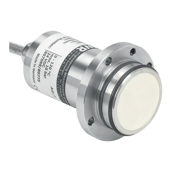
Page 3: System Overview
1. System overview A complete M-Sens 2 FD unit consists of the following components: 1 welding fl ange per sensor • 1 to 3 sensors with 2 m connecting cable • Transmitter MSE 300 up to 3 sensors in a DIN Rail housing or a fi eld housing •... - Page 4 The system can be equipped with up to three sensors. Different C-Boxes (C1, C3) are used accordingly. C3-Box Transmitter 1 (+ 24 V) 2 (GND) Sensor 3 (A) 4 (B) Shield Sensor Sensor max. 300 m Fig. 3: Overview with C3-Box and fi eld housing C3-Box Transmitter 16 (+ 24 V)
-
Page 5: Function
2. Function The M-Sens 2 FD sensor functionality is based on precise high-frequency measurement and direct digitalization of measured values, where from results a high resolution. As the material surface and capillary moisture influences strongly its specific conductive capacity, the moisture can be measured exactly by a constant averaged bulk density. -
Page 6: Safety
If a damage is found, it is to repaired before further operation of the instruments. Technical progress ENVEA - SWR engineering reserves the right to adapt technical data to the technical progress without • particular advance notice. If you have any questions, ENVEA - SWR engineering will be pleased to... -
Page 7: Mounting And Installation
4. Mounting and installation 4.1 Delivery range Evaluation unit in DIN Rail housing or field housing • Sensor • Operating instructions • C1-Box or C3-Box • Welding flange • 4.2 Auxiliary Screw driver 2.5 mm • Allen key 5 mm •... - Page 8 APPLICATIONS - PRACTICAL EXAMPLES Installation in a screw • The installation of a moisture sensor in screw feeders proved to be very advantageous, since the material passes by the sensor window in even intervals and with relatively constant bulk density. 13,1 Moisture Screw feeder...
- Page 9 Installation in a bin • Another installation alternative is to mount a sensor at a bins outlet. Due to constant bulk density in case of a filled bin, the sensor finds an almost unchanging measuring field for monitoring the residual moisture.
- Page 10 Moisture measurement in a mixer • M-Sens 2 FD can be installed, even later on, in all types of mixers. The measuring values logging is done by within the moving material during the mixer procedure. With the measured moisture value of the material in the dryer process parameters like detention time and dosage quantity can be controlled.
-
Page 11: Mounting Of The Transmitter
4.4 Mounting of the transmitter The transmitter can be installed at a maximum distance of 300 m from the sensor. A cable of type “Ölflex Classic 110 CY” is recommended. The cable should be four wired, twisted and shielded. A minimum cable cross-section of 0.75 mm²... - Page 12 113 mm 125 mm 50 mm max. max. 13 mm 13 mm Fig. 14: Field housing for the C1-Box 175 mm 35 mm 35 mm 35 mm 163 mm max. max. max. max. 13 mm 13 mm 13 mm 13 mm Fig.
-
Page 13: Use In The Explosion Hazard Area
4.5 Use in the explosion hazard area DustEx labelling: II 1D Ex maD iaD 20 T120 °C - Group of equipment 2 - Equipment category: 1 - Zone 20 - For explosive mixtures of air and flammable dust - Permissible process temperature 0 ... 80 °C - Maximum surface temperature 135 °C with Ta = 60 °C GasEx labelling: II 1G Ex ma ia CII T4... -
Page 14: Electrical Connection
Electrical connection 5.1 DIN Rail housing Current output Current output Input Input - 4 ... 20 mA + 4 ... 20 mA Power supply Power supply 0 V DC + 24 V DC Not used Alarm relay Alarm relay Alarm relay NC (break contact) NO (make contact) Sensor... -
Page 15: Field Housing Terminal Layout
5.2 Field housing terminal layout Fig. 19: Electrical connection Transmitter Terminal No. Connection Power supply connection L / +24 V Input power supply 230 V / 50 Hz, 110 V / 60 Hz (optional 24 V DC) N / 0 V Input power supply 230 V / 50 Hz, 110 V / 60 Hz (optional 24 V DC) Earth Connections... -
Page 16: Terminal Layout C-Boxes
5.3 Terminal layout C-Boxes Transmitter Sensor 1 Sensor 2 Sensor 3 Fig. 20: Electrical connection for the C3-Box Sensor 1 Transmitter Cable gland M 20 x 1.5 Fig. 21: Electrical connection for the C1-Box... -
Page 17: Commissioning
6. Commissioning At the first commissioning of the M-Sens 2 FD it is necessary to calibrate the sensor. Please consider: Correct connection between sensor, C1-box and evaluation unit. • Correct installation of the sensor in the process. • In case of negative results in spite of consideration of the points as stated above, please contact SWR. Commissioning of the M-Sens 2 FD After the delivery the sensor is not calibrated to the product(s), so each calibration and parameterization has to be executed during the commissioning. -
Page 18: Menu Structure Of M-Sens 2 Fd
7. Menu structure of M-Sens 2 FD The menu structure supports the user when adjusting the measuring range, the calibration, the measurement values and the choice of additional functions. In this connection, the numbering both on the display and in the PC interface is identical: Measuring range Set all relevant measuring range settings... - Page 19 Calibration Store the calibration curve. Calibration factor Input: 0.01 … 9.99 Factor for the subsequent adjustment of the actual measurement. All measurements are measured with this factor. Calibration filter s Input: 1 … 9999 Filter time for recording the raw value during calibration.
- Page 20 Alarm Setting for the alarm via the relay contacts. Selection: Alarm type The relay is activated when the measured None / Min / Max / Flow value exceeds the max. limit or undershoots the min. limit. “Flow” alarm is activated when measured noise value exceeds the setup limit.
- Page 21 Analog output Setting and calibrating the analogue output. Lower limit Input: 0 … 22 mA Standard setting: 4 mA Upper limit Input: 0 … 22 mA Standard setting: 20 mA Alarm value Input: 0 … 22 mA Value to be output at pending alarm (Standard setting 2 mA) Selection: Alarm: Alarm is output...
- Page 22 Analogue output 3 Submenu 4.7.1 Calibration 4 mA Selection: Key functions can be used to set the current Setting the output current and equalise it to the receiver side Selection: 4.7.2 Calibration 20 mA Key functions can be used to set the current Setting the output current and equalise it to the receiver side The current output can be calibrated so that the zero point (output of 4 mA) is set to the background...
- Page 23 Pulse output Passive signal for pulse cleaning. Function Selection: OFF / Cleaning OFF: No pulse output Cleaning: Option for actuation of a solenoid value for pneumatic air flushing. Pulse period Input: 1 s … 600 s Duration between two pulses Pulse length Input: 1 s …...
- Page 24 Current input Note: Only available on fieldhousing. Option for auto-correction by external current signal. The signal is not electrically isolated. If the connection is incorrect, the CPU of the transmitter may be destroyed. An external, galvanic isolation by means of a current disconnector or similar must be provided. Selection: Input calib.
- Page 25 (This function should only be used by trained personnel of ENVEA - SWR engineering.) Average: Calibration by the average value from raw values: The throughput will be calculated with a common calibration table after forming the average from raw values.
- Page 26 7.2.5 Sensor Selection: The transmitter verifies the availability of SolidFlow 2.0 / PicoFlow / registered sensors on the selected type, ProSens / SpeedFlow 2.0 / calculates the measurement values on this Paddy / MaxxFlow HTC / basis and signals if necessary corresponding DensFlow / SlideControl / errors.
- Page 27 Only according to instructions from personnel of ENVEA - SWR engineering: If a detailed error analysis is necessary, a copy of all ModBus registers can be stored as a text file in the installation folder of the software by clicking on the sensor dump.
-
Page 28: Operator Interface
8. Operator interface The transmitter is a multi-sensor transmitter. It is therefore strongly recommended to check before commissioning whether the correct sensor is selected in menu System. The operator interface differs depending on the system design: • DIN Rail housing without touchscreen, operation via PC software only •... -
Page 29: Display
8.2 Display The display is touch-sensitive. Available keys are displayed directly in context. When the measuring system is first started, a query is initiated to select the language and sensor. If no selection is made, the initialization disappears and the German language with a SolidFlow 2.0 sensor is selected. Initialization screen when the transmitter in the field housing started first time. - Page 30 The [ I ] key can be used to call up an information window, Sensor status in which the raw value, temperature and status of the Temp Raw value Stat sensors can be checked. 63.0 0.000123 63.0 0.000213 If any data has been changed, the change will only be taken into account when you exit the complete menu structure and Save changes? answer [ Yes ] when asked if you wish to save the changes.
-
Page 31: Pc Interface
8.3.1 ModBus address 1 8.3.2 Baud rate 9600, 8, E,1 An RS 485 to USB adapter can be purchased from ENVEA - SWR engineering. ✔ For the USB connection to the DIN Rail version is a standard USB-A-B cable included. - Page 32 The edited data is transmitted to the transmitter via “Device program”. Critical data concerning the ModBus communication and the calibration must be confirmed before the parameters are transmitted to the transmitter: ✔ If, when saving the parameters in the transmitter, the system calibration data is changed, this action must be confirmed by checking “Overwrite calibration”.
-
Page 33: Maintenance
In case of a defect during the warranty period, defective components are repaired or are replaced free of charge. Replaced parts turn into the property of ENVEA - SWR engineering. If desired by the costumer that the parts should be repaired or replaced in its factory, then the costumer has to take over the costs for the ENVEA - SWR engineering-service staff. -
Page 34: Technical Data
Data backup Flash memory Pulse output Open Collector - Max. 30 V, 20 mA SWR engineering Messtechnik GmbH Gutedelstraße 31 · 79418 Schliengen (Germany) Fon +49 7635 827248-0 · Fax +49 7635 827248-48 · www.swr-engineering.com PART OF THE ENVEA GROUP...
Need help?
Do you have a question about the envea M-Sens 2 FD and is the answer not in the manual?
Questions and answers