Table of Contents
Advertisement
Quick Links
Advertisement
Table of Contents

Related Manuals for Asus Crosshair IV Extreme


Summary of Contents for Asus Crosshair IV Extreme
- Page 1 Crosshair IV Extreme...
- Page 2 Product warranty or service will not be extended if: (1) the product is repaired, modified or altered, unless such repair, modification of alteration is authorized in writing by ASUS; or (2) the serial number of the product is defaced or missing.
-
Page 3: Table Of Contents
France Restricted Wireless Frequency Bands ........x IC Radiation Exposure Statement for Canada ........xi Safety information ..................xii About this guide ..................xiv Crosshair IV Extreme specifications summary ........xvi Chapter 1: Product introduction Welcome! ..................1-1 Package contents ................. 1-1 Special features ................ - Page 4 BIOS Setup Managing and updating your BIOS ..........3-1 3.1.1 ASUS Update utility ............3-1 3.1.2 ASUS EZ Flash 2 utility ........... 3-4 3.1.3 ASUS CrashFree BIOS 3 utility ........3-5 BIOS Setup program ..............3-6 3.2.1 BIOS menu screen ............3-7 3.2.2...
- Page 5 Contents 3.2.9 General help ..............3-8 Extreme Tweaker menu ............... 3-9 3.3.1 CPU Level Up [Auto] ............. 3-10 3.3.2 Ai Overclock Tuner [Auto] ..........3-10 3.3.3 CPU Ratio Setting [Auto] ..........3-10 3.3.4 CPU Bus Frequency [XXX] ........... 3-10 3.3.5 PCIE Frequency [XXX] ..........
- Page 6 Boot Device Priority ............3-39 3.7.2 Boot Settings Configuration .......... 3-40 3.7.3 Security ................. 3-41 Tools menu ................. 3-43 3.8.1 ASUS EZ Flash 2 ............3-43 3.8.2 ASUS O.C. Profile ............3-44 3.8.3 GO Button File .............. 3-46 3.8.4 BIOS FlashBack ............3-47 Exit menu ..................
- Page 7 Video menu ..............4-5 4.2.7 ASUS Contact information ..........4-5 4.2.8 Other information ............4-6 Software information ..............4-8 4.3.1 ASUS AI Suite II .............. 4-8 4.3.2 TurboV EVO ..............4-9 4.3.3 FAN Xpert ..............4-11 4.3.4 Probe II ................. 4-12 4.3.5...
-
Page 8: Notices
Notices Federal Communications Commission Statement This device complies with Part 15 of the FCC Rules. Operation is subject to the following two conditions: • This device may not cause harmful interference, and • This device must accept any interference received including interference that may cause undesired operation. -
Page 9: Declaration Of Conformity (R&Tte Directive 1999/5/Ec)
RF exposure warning This equipment must be installed and operated in accordance with provided instructions and the antenna(s) used for this transmitter must be installed to provide a separation distance of at least 20 cm from all persons and must not be co-located or operating in conjunction with any other antenna or transmitter. -
Page 10: Wireless Operation Channel For Different Domains
Wireless Operation Channel for Different Domains N. America 2.412-2.462 GHz Ch01 through CH11 Japan 2.412-2.484 GHz Ch01 through Ch14 Europe ETSI 2.412-2.472 GHz Ch01 through Ch13 France Restricted Wireless Frequency Bands Some areas of France have a restricted frequency band. The worst case maximum authorized power indoors are: •... -
Page 11: Ic Radiation Exposure Statement For Canada
Canadian Department of Communications Statement This digital apparatus does not exceed the Class B limits for radio noise emissions from digital apparatus set out in the Radio Interference Regulations of the Canadian Department of Communications. This class B digital apparatus complies with Canadian ICES-003. Cet appareil numérique de la classe [B] est conforme à... -
Page 12: Safety Information
Safety information Electrical safety • To prevent electrical shock hazard, disconnect the power cable from the electrical outlet before relocating the system. • When adding or removing devices to or from the system, ensure that the power cables for the devices are unplugged before the signal cables are connected. If possible, disconnect all power cables from the existing system before you add a device. - Page 13 Operation safety • Before installing the motherboard and adding devices on it, carefully read all the manuals that came with the package. • Before using the product, ensure all cables are correctly connected and the power cables are not damaged. If you detect any damage, contact your dealer immediately.
-
Page 14: About This Guide
Refer to the following sources for additional information and for product and software updates. ASUS websites The ASUS website provides updated information on ASUS hardware and software products. Refer to the ASUS contact information. Optional documentation Your product package may include optional documentation, such as warranty flyers, that may have been added by your dealer. - Page 15 Conventions used in this guide To ensure that you perform certain tasks properly, take note of the following symbols used throughout this manual. DANGER/WARNING: Information to prevent injury to yourself when trying to complete a task. CAUTION: Information to prevent damage to the components when trying to complete a task.
-
Page 16: Crosshair Iv Extreme Specifications Summary
C.)/1800(O.C.)/1600(O.C.) / 1333 / 1066 MHz, ECC and non-ECC, un-buffered memory and non-ECC, un-buffered memory *Refer to www.asus.com or user manual for the Memory QVL (Qualified Vendors Lists) QVL (Qualified Vendors Lists) **Due to OS limitation, when installing total memory... - Page 17 MemOK! Onboard Switches: Power / Reset / Core Unlocker / Clr CMOS (at rear) Q-Fan Plus ASUS Fan Xpert ASUS Q-LED (CPU, DRAM, VGA, Boot Device LED) ASUS Q-Connector ASUS Q-Shield ASUS Q-Fan 2 ASUS EZ Flash 2 ASUS CrashFree BIOS 3...
- Page 18 Crosshair IV Extreme specifications summary Manageability WOL by PME, WOR by PME, PXE Back Panel I/O Ports 1 x PS/2 Keyboard port (purple) 2 x External SATA ports 1 x LAN (RJ45) port 2 x USB 3.0/2.0 ports 7 x USB 2.0/1.1 ports (1 port is also for ROG Connect)
-
Page 19: Chapter 1: Product Introduction
This chapter describes the motherboard features and the new technologies it supports. Chapter 1: Product introduction... - Page 20 Chapter summary Welcome! ..................1-1 Package contents ................. 1-1 Special features ................1-2 ROG Crosshair IV Extreme...
-
Page 21: Welcome
Welcome! Thank you for buying an ROG Crosshair IV Extreme motherboard! The motherboard delivers a host of new features and latest technologies, making it another standout in the long line of ASUS quality motherboards! Before you start installing the motherboard, and hardware devices on it, check the items in your package with the list below. -
Page 22: Special Features
Green ASUS This motherboard and its packaging comply with the European Union’s Restriction on the use of Hazardous Substances (RoHS). This is in line with the ASUS vision of creating environment-friendly and recyclable products/packaging to safeguard consumers’ health while minimizing the impact on the environment. -
Page 23: Rog Intelligent Performance & Overclocking Features
POST code and hardware status readouts on your notebook, as well as make on-the-fly parameter adjustments at a purely hardware level. Diagram, power, reset button, flash BIOS through notebook. Refer to page 2-32 for details. ROG Crosshair IV Extreme... - Page 24 USB BIOS FlashBack Refresh the BIOS can never be that easy USB BIOS Flashback must be the most convenient way to flash BIOS ever! It allows overclockers to try their BIOS with the simplist way one can imagine. No need to enter the BIOS or the operating system, just plug the thumb drive into the ROG Connect port &...
-
Page 25: Rog Unique Features
The COP EX allows overclockers to increase chipset voltage without the worries of overheating. It can also be used to monitor and save an overheating GPU. The COP EX allows more freedom and less constraint for maximum performance achievement. ROG Crosshair IV Extreme... -
Page 26: Asus Special Features
Core Unlocker Intelligently Unlocks True Core Performance ASUS Core Unlocker simplifies the activation of a latent AMD CPU—with just a press of a button. Enjoy an instant performance boost by simply unlocking the extra cores, without performing complicated BIOS changes. - Page 27 Conveniently store or load multiple BIOS settings Freely share and distribute favorite overclocking settings The motherboard features the ASUS O.C. Profile that allows users to conveniently store or load multiple BIOS settings. The BIOS settings can be stored in the CMOS or a separate file, giving users freedom to share and distribute their favorite overclocking settings.
- Page 28 MyLogo3 Personalize your system with customizable boot logo The ASUS MyLogo 3 is the new feature present in the motherboard that allows you to personalize and add style to your system with customizable and animated boot logos. SATA on the Go...
-
Page 29: Chapter 2: Hardware Information
This chapter lists the hardware setup procedures that you have to perform when installing system components. It Chapter 2: Hardware includes description of the jumpers and connectors on the motherboard. information... - Page 30 Expansion slots ................2-24 Jumper ..................2-30 RC Bluetooth card ..............2-31 I/O shield Installation ..............2-32 Connectors ................. 2-33 2.10 Starting up for the first time ............2-54 2.11 Turning off the computer ............2-55 ROG Crosshair IV Extreme...
-
Page 31: Before You Proceed
Before you install or remove any component, ensure that the ATX power supply is switched off or the power cord is detached from the power supply. Failure to do so may cause severe damage to the motherboard, peripherals, or components. ROG Crosshair IV Extreme... - Page 32 Onboard LEDs The motherboard comes with a set of LEDs that indicate the voltage conditions of CPU, memory, northbridge and southbridge. You may adjust the voltages in BIOS. There are also an LED for hard disk drive activity and an onboard switch for power status. For more information about voltage adjustment, refer to 3.3 Extreme Tweaker menu.
- Page 33 The LED does not light up when there is no hard disk drive connected to the motherboard or when the hard disk drive does not function. ROG Crosshair IV Extreme...
- Page 34 BIOS LED The BIOS LEDs help indicate the BIOS activity. Press the BIOS button to switch between BIOS1 and BIOS2 and the LED lights up when the corresponding BIOS is in use. GO LED Blinking: Indicates that MemOK! is enabled before POST. Lighting: Indicates that the system loads the preset profile (GO_Button file) for temporary overclocking when in OS.
- Page 35 ON, in sleep mode, or in soft-off mode. This is a reminder that you should shut down the system and unplug the power cable before removing or plugging in any motherboard component. The illustration below shows the location of the onboard power-on switch. ROG Crosshair IV Extreme...
-
Page 36: Motherboard Overview
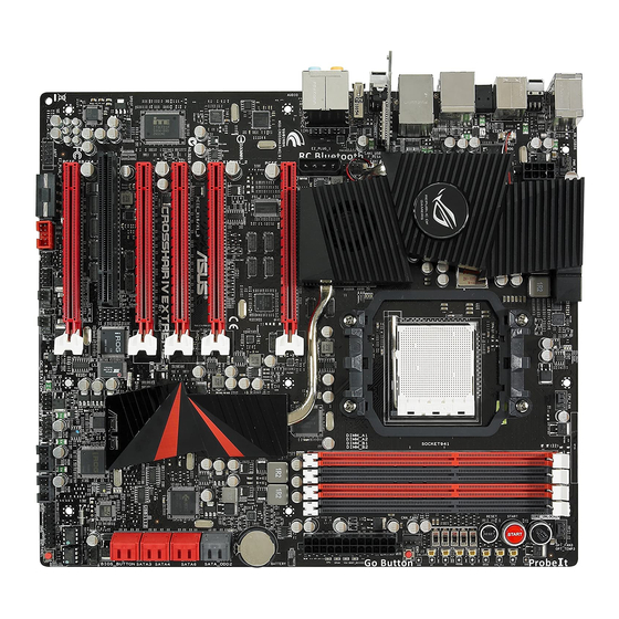
Motherboard overview 2.2.1 Motherboard layout Chapter 2: Hardware information... -
Page 37: Layout Contents
2-46 Digital audio connector (4-1 pin SPDIF_OUT) 2-46 RC Bluetooth connector (12-1 pin RC_Bluetooth) 2-32 Optional fan-thermal module connector (2-pin FAN1) 2-44 Refer to 2.9 Connectors for more information about rear panel connectors and internal connectors. ROG Crosshair IV Extreme... -
Page 38: Placement Direction
2.2.3 Placement direction When installing the motherboard, ensure that you place it into the chassis in the correct orientation. The edge with external ports goes to the rear part of the chassis as indicated in the image below. 2.2.4 Screw holes Place nine (9) screws into the holes indicated by circles to secure the motherboard to the chassis. -
Page 39: Central Processing Unit (Cpu)
Unlock the socket by pressing the lever sideways, then lift it up to a 90º angle. Socket lever Ensure that the socket lever is lifted up to a 90º angle; otherwise, the CPU will not fit in completely. ROG Crosshair IV Extreme... - Page 40 Position the CPU above the socket such that the CPU corner with the gold triangle matches the socket corner with a small triangle. Carefully insert the CPU into the socket until it fits in place. Gold triangle Small triangle When the CPU is in place, push down the socket lever to secure the CPU.
-
Page 41: Installing The Cpu Heatsink And Fan
Your boxed CPU heatsink and fan assembly should come with installation instructions for the CPU, heatsink, and the retention mechanism. If the instructions in this section do not match the CPU documentation, follow the latter. ROG Crosshair IV Extreme 2-11... - Page 42 Attach one end of the retention bracket to the retention module base. Align the other end of the retention bracket (near the retention bracket lock) to the retention module base. A clicking sound denotes that the retention bracket is in place. Ensure that the fan and heatsink assembly perfectly fits the retention mechanism module...
- Page 43 Connect the CPU fan cable to the connector on the motherboard labeled CPU_FAN. • Do not forget to connect the CPU fan connector! Hardware monitoring errors can occur if you fail to plug this connector. • This connector is backward compatible with old 3-pin CPU fan. ROG Crosshair IV Extreme 2-13...
-
Page 44: System Memory
System memory 2.4.1 Overview The motherboard comes with four Double Data Rate 3 (DDR3) Dual Inline Memory Modules (DIMM) sockets. A DDR3 module has the same physical dimensions as a DDR2 DIMM but is notched differently to prevent installation on a DDR2 DIMM socket. DDR3 modules are developed for better performance with less power consumption. -
Page 45: Memory Configurations
To operate at the vendor-marked or at a higher frequency, refer to section 3.3 Extreme Tweaker menu for manual memory frequency adjustment. • For system stability, use a more efficient memory cooling system to support a full memory load (4 DIMMs) or overclocking condition. ROG Crosshair IV Extreme 2-15... - Page 46 Crosshair IV Extreme Motherboard Qualified Vendors Lists (QVL) DDR��2000MH�� capability 3-2000MHz capability -2000MHz capability Vendors Part No. Size SS/DS Timing Voltage DIMM socket support (Optional) 1 DIMM 2 DIMM 4 DIMM Apacer 78.AAGD5.9KD(XMP) 6GB(3 x 2GB) 9-9-9-27 • • Crucial BL12864BE2009.8SFB3(EPP)
- Page 47 Crosshair IV Extreme Motherboard Qualified Vendors Lists (QVL) DDR��1���MH�� capability 3-1866MHz capability -1866MHz capability Vendors Part No. Size SS/DS Timing Voltage DIMM socket support (Optional) 1 DIMM 2 DIMM 4 DIMM CORSAIR TR3X6G1866C9DVer4.1(XMP) 6GB(3 x 2GB) 9-9-9-24 1.65 • G.SKILL...
- Page 48 Crosshair IV Extreme Motherboard Qualified Vendors Lists (QVL) DDR��1�00MH�� capability 3-1600MHz capability -1600MHz capability Vendors Part No. Size SS/DS Timing Voltage DIMM socket support (Optional) 1 DIMM 2 DIMM 4 DIMM CORSAIR TR3X3G1600C8DVer2.1(XMP) 3GB(3 x 1GB) 8-8-8-24 1.65 • •...
- Page 49 4GB(2 x 2GB) 7-7-7-20 • • • Patriot PVT36G1600ELK 6GB(3 x 2GB) 9-9-9-24 1.65 • • • Patriot PVT36G1600ELK 6GB(3 x 2GB) 9-9-9-24 1.65 • • • Patriot PVT36G1600LLK(XMP) 6GB(3 x 2GB) 8-8-8-24 1.65 • • • ROG Crosshair IV Extreme 2-19...
- Page 50 Crosshair IV Extreme Motherboard Qualified Vendors Lists (QVL) DDR��1���MH�� capability 3-1333MHz capability -1333MHz capability Vendors Part No. Size Chip Brand Chip NO. Timing Voltage DIMM socket support (Optional) 1 DIMM 2 DIMM 4 DIMM Apacer 78.01GC6.9L0 SS Apacer AM5D5808DEJSBG •...
- Page 51 • • MFACR423PA0105 DS PQI PQC32808E15R • • • Silicon SP001GBLTU1333S01 SS NANYA NT5CB128M8AN-CG - • • Power Silicon SP001GBLTU133S02 SS S-POWER I0YT3E0 • • Power Silicon SP002GBLTU133S02 DS S-POWER I0YT3E0 • • • Power ROG Crosshair IV Extreme 2-21...
- Page 52 Crosshair IV Extreme Motherboard Qualified Vendors Lists (QVL) DDR��10��MH�� capability 3-1067MHz capability -1067MHz capability Vendor Part No. Size Chip Chip NO. Timing Voltage DIMM socket support Brand Lable (Bios) 1 DIMM 2 DIMM 4 DIMM Crucial CT12864BA1067.8FF SS MICRON D9KPT •...
-
Page 53: Installing A Dimm
DIMM. Always insert the DIMM into the socket VERTICALLY to prevent DIMM notch damage. 2.4.4 Removing a DIMM Press the retaining clip outward to unlock the DIMM. Remove the DIMM from the socket. ROG Crosshair IV Extreme 2-23... -
Page 54: Expansion Slots
Expansion slots In the future, you may need to install expansion cards. The following sub-sections describe the slots and the expansion cards that they support. Ensure to unplug the power cord before adding or removing expansion cards. Failure to do so may cause you physical injury and damage motherboard components. -
Page 55: Interrupt Assignments
– – – – – – – HD Audio – – – – – shared – IEEE 1394 – – shared – – – – – PCI1 shared – – – – – – – ROG Crosshair IV Extreme 2-25... -
Page 56: Pci Slot
2.5.4 PCI slot The PCI slot supports cards such as a LAN card, SCSI card, USB card, and other cards that comply with PCI specifications. Refer to the figure below for the location of the slot. 2.5.5 PCI Express x16 slots This motherboard has five PCI Express x16 slots that support PCI Express x16 cards complying with the PCI Express specifications. - Page 57 CrossLinx 3 makes it possible to experiment with different configurations of graphics cards for maximum performance. On Crosshair IV Extreme, a unique layout design features a total of five PCI Express expansion slots. Two provide dedicated native graphics card support for either a single GPU or traditional CrossFire.
- Page 58 Single VGA configurations with without VGA slot Bandwidth YDRA OGIX YDRA OGIX Single VGA PCIE_X16_1 X16 mode Other cards PCIE_X16/X1_3 X16 mode Dual VGA configurations with without VGA slot Bandwidth YDRA OGIX YDRA OGIX 1st VGA PCIE_X16_1 X16 mode 2nd VGA PCIE_X16/X1_3 X16 mode Native CrossFireX...
- Page 59 Quad VGA configurations with without VGA slot Bandwidth YDRA OGIX YDRA OGIX 1st VGA PCIE_X16_1 X16 mode 2nd VGA PCIE_X16/X1_2 X16 mode PCIE_X16/X8/ 3rd VGA X8 mode CrossFireX X1_4 4th VGA PCIE_X8/X4_5 X8 mode Other cards PCIE_X16/X1_3 X1 mode • The PCIE slots 1 and 3 are supported by AMD890FX (for ATI CrossFireX only) and slots 2, 4, and 5 by YDRA OGIX (for both ATI CrossFireX and nVIDIA SLI). Refer to page 2-27 for the slot location. •...
- Page 60 Notes for enabling YDRA OGIX • YDRA OGIX should only be enabled when using : Supported graphic cards. Supported graphic driver revisions iii. Supported applications / games • No bridge is required to enable YDRA OGIX. • YDRA OGIX support is only available under Windows VISTA SP2 or later and Windows 7 operating system.
-
Page 61: Jumpers
• Due to the chipset behavior, AC power off is required to enable C.P.R. function. You must turn off and on the power supply or unplug and plug the power cord before rebooting the system. ROG Crosshair IV Extreme 2-31... -
Page 62: Rc Bluetooth Card
RC Bluetooth card RC Bluetooth card layout Antenna: Receives the Bluetooth signal. The plastic cap on the antenna protects it from possible damage. Bluetooth Switch: Toggles the RC Bluetooth function ON and OFF. When the RC Bluetooth is OFF, the normal Bluetooth connection is still available. Bluetooth Connector: Connects the RC_BLUETOOTH connector on the motherboard. -
Page 63: I/O Shield Installation
I/O openings. Be cautious when installing the motherboard. The I/O shield edge springs may damage the I/O ports. The photos above are for reference only, the actual I/O shield may differ by models. ROG Crosshair IV Extreme 2-33... -
Page 64: Connectors
Connectors 2.9.1 Rear panel connectors Rear panel connectors PS/2 keyboard port (purple) External SATA port USB 2.0 ports 1 and 2 Optical S/PDIF Out port USB 2.0 ports 3 and 4 External SATA port LAN (RJ-45) port* USB 3.0 ports 1 and 2 USB 2.0 ports 5 and 6 ROG Connect switch Clear CMOS switch... -
Page 65: Rog Connect Switch And Rc Bluetooth Switch
Press the switch to start to connection. To use USB BIOS FlashBack: Download the latest BIOS from ASUS support website. Rename it C4E.ROM, save it to a USB flash drive and place it in the root directory. Connect the USB flash drive to the ROG Connect port. - Page 66 Refer to the Appendix for the qualified vendor list for the mobile phone before using the RC Bluetooth function. • The RC Bluetooth is designed for the following mobile phone operating systems. Visit the ASUS website at www.asus.com for the latest supported operating system list. Mobile phone OS Version Windows Mobile 6.5/ 6.1/ 6.0 Professional (at display resolution 480*800)
-
Page 67: Audio I/O Connections
Mic In Mic In Mic In Center/ Center/ Orange – – Subwoofer Subwoofer Rear Speaker Rear Speaker Rear Speaker Black – Side Speaker Gray – – – Audio I/O ports Connect to Headphone and Mic ROG Crosshair IV Extreme 2-37... - Page 68 Connect to Stereo / 2.1-channel Speakers Connect to 4.1-channel Speakers Connect to 5.1-channel Speakers 2-38 Chapter 2: Hardware information...
- Page 69 Connect to 7.1-channel Speakers ROG Crosshair IV Extreme 2-39...
-
Page 70: Internal Connectors
2.9.4 Internal connectors AMD SB850 Serial ATA connectors (7-pin SATA 1-6 �red�) AMD SB850 Serial ATA connectors (7-pin SATA 1-6 �red�) These connectors are for the Serial ATA signal cables for Serial ATA hard disk drives and optical disc drives. If you installed Serial ATA hard disk drives, you can create a RAID 0, 1, 5, and 10 configuration with the onboard AMD SB850 RAID controllers. - Page 71 ROG connector (3-pin ROG) This connector is for the box (labeled as Republic of Gamers) on the heatpipe assembly. Connect the cable of the box and it lights when the system is on. ROG Crosshair IV Extreme 2-41...
- Page 72 480 Mbps connection speed. Never connect a 1394 cable to the USB connectors. Doing so will damage the motherboard! You can connect the USB cable to ASUS Q-Connector (USB, blue) first, and then install the Q-Connector (USB) to the USB connector onboard. 2-42...
- Page 73 OC station connector (8-pin OC_Station) This connector is for ASUS OC Station connection only. Connect one end Connect one end of the supplied data cable to the GP connector on the OC Station and the other end to this connector and USB910 on the motherboard to enjoy easier overclocking.
- Page 74 CPU, chassis, and optional fan connectors (4-pin CPU_FAN, 4-pin PWR_FAN, 4-pin CHA_FAN1–3, 4-pin OPT_FAN1–3) The fan connectors support cooling fans of 350 mA–2000 mA (24 W max.) or a total of 1 A–7 A (84 W max.) at +12V. Connect the fan cables to the fan connectors on the motherboard, ensuring that the black wire of each cable matches the ground pin of the connector.
- Page 75 The optional fan1/2/3 can work with the temperature sensors for a better cooling effect. Enable OPT FAN1/2/3 overheat protection in BIOS if you connect thermal sensor cables to these connectors. ROG Crosshair IV Extreme 2-45...
- Page 76 10. Digital audio connector (4-1 pin SPDIF_OUT) This connector is for an additional Sony/Philips Digital Interface (S/PDIF) port(s). Connect the S/PDIF Out module cable to this connector, then install the module to a slot opening at the back of the system chassis. The S/PDIF module is purchased separately.
- Page 77 Appendix for the certified 500W power supply or above. • If you are uncertain about the minimum power supply requirement for your system, refer to the Recommended Power Supply Wattage Calculator at http://support.asus.com/PowerSupplyCalculator/PSCalculator. aspx?SLanguage=en-us for details. ROG Crosshair IV Extreme 2-47...
- Page 78 13. System panel connector (20-8 pin PANEL) This connector supports several chassis-mounted functions. • System power LED (2-pin PLED) This 2-pin connector is for the system power LED. Connect the chassis power LED cable to this connector. The system power LED lights up when you turn on the system power, and blinks when the system is in sleep mode.
- Page 79 14. ASUS Q-Connector (system panel) Use the ASUS Q-Connector to connect/disconnect the chassis front panel cables. To install the ASUS Q-Connector: Connect the front panel cables to the ASUS Q-Connector. Refer to the labels on the Q-Connector to know the detailed...
-
Page 80: Onboard Switches
2.9.5 Onboard switches Onboard switches allow you to fine-tune performance when working on a bare or open-case system. This is ideal for overclockers and gamers who continually change settings to enhance system performance. Power-on switch Press the power-on switch to wake/power up the system. Reset switch Press the reset switch to reboot the system. - Page 81 (GO_Button file) for temporary overclocking when in BIOS button The motherboard comes with two BIOS. Press the BIOS button to switch BIOS and load different BIOS settings. The nearby BIOS LEDs indicate the BIOS you are using. ROG Crosshair IV Extreme 2-51...
- Page 82 The system will use the last setting you have made. • If you clear the CMOS or load the BIOS setup defaults, the ASUS Core Unlocker item in the BIOS menu follows the current setting of the Core Unlocker switch.
- Page 83 These slide switches allows you to enable and disable the corresponding PCIe x16 slots. When one of the installed PCIe x16 cards is out of order, you can use the slide switch to find out the faulty one without removing the cards. ROG Crosshair IV Extreme 2-53...
-
Page 84: Probeit
2.9.6 ProbeIt The ROG ProbeIt feature provides a nice touch for your convenient and accurate OC settings. No time wasted fumbling around on the complicated motherboard layout, the clearly marked area gives you easier access to the measure points when a multitester is employed for more accurate measurements during your busy overclocking work. -
Page 85: 2.10 Starting Up For The First Time
No VGA detected short beeps One continuous beep followed by four Hardware component failure short beeps At power on, hold down the <Delete> key to enter the BIOS Setup. Follow the instructions in Chapter 3. ROG Crosshair IV Extreme 2-55... -
Page 86: 2.11 Turning Off The Computer
2.11 Turning off the computer 2.11.1 Using the OS shut down function If you are using Windows Vista™/ Windows ® ® Click the Start button then select Shut Down. The power supply should turn off after Windows shuts down. ® If you are using Windows ®... -
Page 87: Chapter 3: Bios Setup
This chapter tells how to change the system settings through the BIOS Setup menus. Detailed descriptions of the BIOS parameters are also provided. BIOS Setup... - Page 88 Chapter summary Managing and updating your BIOS ..........3-1 BIOS Setup program ..............3-6 Extreme Tweaker menu ............... 3-9 Main menu .................. 3-16 Advanced menu ................. 3-21 Power menu ................3-32 Boot menu .................. 3-39 Tools menu ................. 3-43 Exit menu ..................3-48 ROG Crossfire IV Extreme...
-
Page 89: Managing And Updating Your Bios
BIOS in the future. Copy the original motherboard BIOS using the ASUS Update utility. 3.1.1 ASUS Update utility The ASUS Update is a utility that allows you to manage, save, and update the motherboard BIOS in Windows environment. The ASUS Update utility allows you to: ®... - Page 90 To update the BIOS through the Internet: desktop by clicking Start Launch the ASUS Update utility from the Windows ® > Programs > ASUS > ASUSUpdate > ASUSUpdate. The ASUS Update main window appears. Select Update BIOS from the Select the ASUS FTP site nearest...
- Page 91 To update the BIOS through a BIOS file: desktop by clicking Start Launch the ASUS Update utility from the Windows ® > Programs > ASUS > ASUSUpdate > ASUSUpdate. The ASUS Update main window appears. Select Update BIOS from a file option from the drop-down menu, then click Next.
-
Page 92: Asus Ez Flash 2 Utility
3.1.2 ASUS EZ Flash 2 utility The ASUS EZ Flash 2 feature allows you to update the BIOS without having to use a DOS-based utility. The EZ Flash 2 utility is built in the BIOS chip so it is accessible by pressing <Alt> + <F2> during the Power-On Self Tests (POST). -
Page 93: Asus Crashfree Bios 3 Utility
3.1.3 ASUS CrashFree BIOS 3 utility The ASUS CrashFree BIOS 3 utility is an auto recovery tool that allows you to restore the BIOS file when it fails or gets corrupted during the updating process. You can restore a corrupted BIOS file using the motherboard support DVD or a USB flash drive that contains the BIOS file. -
Page 94: Bios Setup Program
The BIOS Setup screens shown in this section are for reference purposes only, and may not exactly match what you see on your screen. • Visit the ASUS website at www.asus.com to download the latest BIOS file for this motherboard. Chapter 3: BIOS Setup... -
Page 95: Bios Menu Screen
3.2.1 BIOS menu screen Menu items Menu bar Configuration fields General help Crossfire IV Extreme BIOS Setup Version 0243 Extreme Tweaker Main Advanced Power Boot Tools Exit Use [ENTER], [TAB] System Time [13:51:25] or [SHIFT-TAB] to System Date [Thu 08/05/2010] select a field. Language [English] Use [+] or [-] to configure system Date. SATA1 [HDT722516DLA380] SATA2 [Not Detected] SATA3 [ATAPI DVD D DH1] SATA4 [Not Detected]... -
Page 96: Menu Items
3.2.4 Menu items The highlighted item on the menu bar displays the specific items for that menu. For example, selecting Main shows the Main menu items. The other items (Advanced, Power, Boot, and Exit) on the menu bar have their respective menu items. -
Page 97: Extreme Tweaker Menu
Extreme Tweaker menu The Extreme Tweaker menu items allow you to configure overclocking-related items. Take caution when changing the settings of the Extreme Tweaker menu items. Incorrect field values can cause the system to malfunction. The default values of the following items vary depending on the CPU and memory modules you install on the motherboard. -
Page 98: Cpu Level Up [Auto]
3.3.1 CPU Level Up �Auto� Allows you to select a CPU level, and the related parameters will be automatically adjusted according to the selected CPU level. If you want to manually configure the settings in detail, set Ai Overclock Tuner to [Manual] after selecting a CPU level. 3.3.2 Ai Overclock Tuner �Auto�... -
Page 99: Cpu/Nb Frequency [Auto]
3.3.7 CPU/NB Frequency �Auto� Allows you to set the ratio between NB clock and the CPU Bus frequency. Configuration options: [Auto] [1400MHz] [1600MHz] [1800MHz] [2000MHz] 3.3.8 HT Link Speed �Auto� Allows you to set the HyperTransport link speed. Configuration options: [Auto] [200MHz] [400MHz] [600MHz] [800MHz] [1000MHz] [1200MHz] [1400MHz] [1600MHz] [1800MHz] [2000MHz] �.�.9 DRAM Timing Configuration... -
Page 100: Dram Driving Configuration
DRAM 2nd Information: 7-2-5-4-3-110-7.8ms-IT The values vary depending on your settings of the following sub-items: DRAM READ to WRITE Delay 7 [Auto] Configuration options: [Auto] [3 DRAM Clock] – [17 DRAM Clock] DRAM WRITE to READ Delay(DD) 2 [Auto] Configuration options: [Auto] [2 DRAM Clock] – [10 DRAM Clock] DRAM WRITE to READ Delay(SD) 5 [Auto] Configuration options: [Auto] [4 DRAM Clock] –... -
Page 101: Extreme Ov [Disabled]
Processor ODT 60ohms �Auto� Configuration options: [Auto] [240 ohms +/- 20%] [240 ohms +/- 20%] DCT1 Information: CKE drive strength 2x �Auto� Configuration options: [Auto] [1x] [1.25x] [1.5x] [2x] CS/ODT drive strength 2x �Auto� Configuration options: [Auto] [1x] [1.25x] [1.5x] [2x] ADDR/CMD drive strength 2x �Auto�... -
Page 102: Cpu Pwr Frequency [Auto]
CPU Voltage �Auto� Allows you to set the CPU voltage. This item appears only when you set CPU/NB Voltage Mode to [Manual]. The values range varies with CPU. CPU/NB Voltage �Auto� Allows you to set the CPU/NB voltage. This item appears only when you set CPU/ NB Voltage Mode to [Manual]. -
Page 103: Vddr Voltage [Auto]
3.3.20 VDDR Voltage �Auto� Allows you to set the VDDR voltage. The values range from 1.20575V to 1.80200V with a 0.01325V interval. The text color in the configuration field indicates voltage The text color in the configuration field indicates voltage condition. -
Page 104: Main Menu
Main menu When you enter the BIOS Setup program, the Main menu screen appears, giving you an overview of the basic system information. Refer to section 3.2.1 BIOS menu screen for information on the menu screen items and how to navigate through them. Crossfire IV Extreme BIOS Setup Version 0243 Extreme Tweaker Main Advanced Power Boot Tools Exit... -
Page 105: Sata 1–6
3.4.4 SATA 1–6 While entering Setup, the BIOS automatically detects the presence of Serial ATA devices. There is a separate sub-menu for each SATA device. Select a device item then press <Enter> to display the SATA device information. Crossfire IV Extreme BIOS Setup Version 0243 Main SATA 1... - Page 106 PIO Mode �Auto� [Auto] Allows automatic selection of the PIO (Programmed input/output) modes, which correspond to different data transfer rates. [0] [1] – [4] Set the PIO mode to Mode 0, 1, 2, 3, or 4. DMA Mode �Auto� DMA (Direct Memory Access) allows your computer to transfer data to and from the hardware devices installed with much less CPU overhead.
-
Page 107: Storage Configuration
�.4.5 Storage Configuration The items in this menu allow you to set or change the configurations for the SATA devices installed in the system. Select an item then press <Enter> if you want to configure the item. Crossfire IV Extreme BIOS Setup Version 0243 Main Storage Configuration... -
Page 108: System Information
SATA Port5 - Port6 [IDE] [IDE] Set to [IDE] when you want to use the Serial ATA hard disk drives as Parallel ATA physical storage devices. [RAID] Set to [RAID] when you want to create a RAID configuration from the SATA hard disk drives. [AHCI] Set to [AHCI] when you want the SATA hard disk drives to use the AHCI (Advabced Host Controller Interface). -
Page 109: Advanced Menu
Crossfire IV Extreme BIOS Setup Version 0243 Advanced CPU Configuration Options AGESA Version: 3.7.0.1 Disabled AMD Athlon(tm) II X3 405e Processor Enabled Revision: C3 Cache L1: 384 KB Cache L2: 1536 KB Cache L3: N/A Speed : 2300MHz uCode Patch Level : 0x10000B6 Microcode Updation [Enabled] ←→ Select Screen Secure Virtual Machine Mode [Enabled] ↑↓ Select Item Cool’n’Quiet [Disabled] F1 General Help C1E Support [Disabled] F10 Save and Exit ASUS Core Unlocker [Disabled] ESC Exit CPU Core Activation [Auto] v02.61 (C)Copyright 1985-2010, American Megatrends, Inc. ROG Crossfire IV Extreme 3-21... - Page 110 Enables the C1E support function. This item should be enabled in order to enable the Enhanced Halt Sate. [Disabled] Disables this function. ASUS Core Unlocker �Disabled� Allows you to unlock the CPU core and get the full computing power. Configuration options: [Disabled] [Enabled] CPU Core Activation �Auto�...
-
Page 111: Chipset
3.5.2 Chipset The Chipset menu allows you to change the advanced chipset settings. Select an item then press <Enter> to display the sub-menu. Crossfire IV Extreme BIOS Setup Version 0243 Advanced Nrothbridge Chipset Settings DRAM Controller Configuration ECC Configuration Primary Display Adapter [PCI-E] IOMMU [Disabled] DRAM Controller Configuration Crossfire IV Extreme BIOS Setup... - Page 112 ECC Configuration BIOS SETUP UTILITY Version 0243 Version 0243 Advanced ECC Configuration Set the level of ECC protection. Note: ECC Mode [Disabled] The ‘Super‘ ECC mode DRAM ECC Enable [Disabled] dynamically sets DRAM SCRUB REDIRECT [Disabled] the DRAM scrub rate 4-Bit ECC Mode [Disabled] so all of memory is DRAM BG Scrub [1.31ms] scrubbed in 8 hours. Data Cache BG Scrub [Disabled] L2 Cache BG Scrub [Disabled] L3 Cache BG Scrub [Disabled] ECC Mode [Disabled] Allows you to set the level of ECC protection. Configuration options: [Disabled] [Basic] [Good] [Super] [Max] [User] The following items become user-configurable when you set ECC Mode to [User]...
- Page 113 L2 Cache BG Scrub �Disabled� Disables or sets the L2 Cache BG Scrub. This item allows the cache RAM to be corrected when idle. Configuration options: [Disabled] [40ns] [80ns] [160ns] [320ns] [640ns] [1.28us] [2.56us] [5.12us] [10.2us] [20.5us] [41.0us] [81.9us] [163.8us] [327.7us] [655.4us] [1.31ms] [2.62ms] [5.24ms] [10.49ms] [20.97ms] [42.00ms] [84.00ms] L3 Cache BG Scrub �Disabled�...
-
Page 114: Onboard Devices Configuration
�.5.� Onboard Devices Configuration Crossfire IV Extreme BIOS Setup Version 0243 Advanced Onboard Device Configuration Get your best overclocking record! Onboard Device [Standard] “Onboard Device” is to disable all the HD Audio Azalia Device [Enabled] unnecessary devices Front Panel Type [HD] when you want to reach SPDIF OUT Type [SPDIF] your best overclocking Onboard LAN [Enabled] record. But it will Onboard LAN Boot ROM [Disabled] keep lan port alive to Onboard 1394 Controller [Enabled] submit your score. Onboard ATA Controller 1 [Enabled] Onboard ATA Controller 2 [Enabled]... - Page 115 Onboard ATA Controller 2 �Enabled� [Disabled] Disables the onboard ATA controller of SATA_ODD1/2. [Enabled] Enables the onboard ATA controller of SATA_ODD1/2. Onboard ATA Controller ROM [Enabled] [Enabled] Enables the onboard ATA controller ROM. [Disabled] Disables the onboard ATA controller ROM. Onboard USB 3.0 Controller �Enabled�...
-
Page 116: Usb Configuration
�.5.4 USB Configuration The items in this menu allows you to change the USB-related features. Select an item then press <Enter> to display the configuration options. Crossfire IV Extreme BIOS Setup Version 0243 Advanced USB Configuration Enable support for Module Version - 2.24.5-13.4 all USB ports. USB Devices Enabled: 1 Drive USB Support [Enabled]... -
Page 117: Pcipnp
3.5.5 PCIPnP The PCIPnP menu items allow you to change the advanced settings for PCI/PnP devices. BIOS Setup UTILITY Advanced Advanced PCI/PnP Settings NO: lets the BIOS configure all the WARNING: Setting wrong values in below sections devices in the may cause system to malfunction. system. Plug And Play O/S [No] Plug And Play O/S �No� [Yes] When set to [Yes] and if you install a Plug and Play operating system, the operating system configures the Plug and Play devices not required for boot. - Page 118 The following items appear only when you set All LED Control to [Enabled]. ROG Logo [Enabled] Allows you to enable or disable the onboard ROG logo LED. Configuration options: [Enabled] [Disabled] POST State LEDs [Enabled] Allows you to enable or disable the onboard POST State LEDs. Configuration options: [Enabled] [Disabled] Voltiminder LED [Enabled] Allows you to enable or disable the onboard Voltiminder LED.
-
Page 119: Irog Configuration
�.5.� iROG Configuration Crossfire IV Extreme BIOS Setup Version 0243 Advanced iROG Configuration iROG Timer Keeper System will record iROG ID_Number Information using time every 1 iROG_1 ID_Number: 39 minute iROG_2 ID_Number: 8 iROG_2 ID_Number: 4 iROG Timer Keeper [Last State] Current Operation time: Total Operation time: ←→ Select Screen ↑↓ Select Item F1 General Help F10 Save and Exit ESC Exit v02.61 (C)Copyright 1985-2010, American Megatrends, Inc. iROG Timer Keeper �Last State� Allows you to set the iROG Time Keeper operation mode. Configuration options: [Last State] [Disabled] [Enabled] 3.5.8 EC Information... -
Page 120: Power Menu
Power menu The Power menu items allow you to change the settings for the Advanced Power Management (APM). Select an item then press <Enter> to display the configuration options. Crossfire IV Extreme BIOS Setup Version 0243 Extreme Tweaker Main Main Advanced Power Boot Tools Exit Advanced Select the ACPI state Suspend Mode [Auto] used for System... -
Page 121: Acpi Apic Support [Enabled]
3.6.4 ACPI APIC Support �Enabled� Allows you to enable or disable the Advanced Configuration and Power Interface (ACPI) support in the Advanced Programmable Interrupt Controller (APIC). [Disabled] When set to [Disabled], the system disable the Advanced Configuration and Power Interface (ACPI) support in the Advanced Programmable Interrupt Controller (APIC). - Page 122 Restore On AC Power Loss �Power Off� [Power Off] The system goes into off state after an AC power loss. [Power On] The system goes into on state after an AC power loss. [Last State] The system goes into either off or on state, whatever the system state was before the AC power loss.
-
Page 123: Hardware Monitor
3.6.6 Hardware Monitor Crossfire IV Extreme BIOS Setup Version 0243 Advanced Hardware Monitor Voltage Monitor Voltage Monitor Temperature Monitor FAN Speed Monitor FAN Speed Control ←→ Select Screen ↑↓ Select Item F1 General Help F10 Save and Exit ESC Exit v02.61 (C)Copyright 1985-2010, American Megatrends, Inc. Voltage Monitor CPU Voltage; CPU/NB Voltage; CPU VDDA Voltage; DRAM Voltage; HT Voltage; NB Voltage; SB Voltage; 3.3V Voltage; 5V Voltage; 12V Voltage The onboard hardware monitor automatically detects the voltage output through the onboard voltage regulators. - Page 124 Fan Speed Monitor CPU FAN; Power FAN; Chassis FAN1/2/3 Speed OPT FAN1/2/3 Speed [xxxxRPM] or [Ignored] / [N/A] The onboard hardware monitor automatically detects and displays the CPU fan, chassis fan, power fan, and optional fan speed in rotations per minute (RPM).
- Page 125 Chassis Q-Fan Function [Disabled] Allows you to enable or disable the CPU fan controller. [Disabled] Disables the CPU Q-fan controller. [Enabled] Enables the CPU Q-fan controller. The following two items appear when you enable the CPU Fan Control feature. Chassis Fan Speed Low Limit �200 RPM� Allows you to set the low speed limit of the chassis fan and the system sends warning message when the fan speed drops below the set value.
- Page 126 OPT Fan 1/2/3 Duty �60%� Allows you to set the fan duty cycle. This item appears when the OPTFan1/2 Control item is set to [Duty Mode]. Configuration options: [40%] [50%] [60%] [70%] [80%] [90%] OPT Fan 1/2/� Low Speed Temp [25˚C] Allows you to set the temperature at which the power fan rotates at low speed.
-
Page 127: Boot Menu
Boot menu The Boot menu items allow you to change the system boot options. Select an item then press <Enter> to display the sub-menu. Crossfire IV Extreme BIOS Setup Version 0243 Extreme Tweaker Main Main Advanced Power Boot Tools Exit Advanced Power Specifies the Boot Boot Settings Device Priority sequence. -
Page 128: Boot Settings Configuration
Enables the full screen logo display feature. [Disabled] Disables the full screen logo display feature. Set this item to [Enabled] to use the ASUS MyLogo3™ feature. AddOn ROM Display Mode �Force BIOS� Sets the display mode for option ROM. [Force BIOS] [Keep Current] . -
Page 129: Security
3.7.3 Security The Security menu items allow you to change the system security settings. Select an item then press <Enter> to display the configuration options. Crossfire IV Extreme BIOS Setup Version 0243 Boot <Enter> to change Security Settings password. <Enter> again to Supervisor Password :Not Installed disabled password User Password :Not Installed Change Supervisor Password... - Page 130 After you have set a supervisor password, the other items appear to allow you to change other security settings. Crossfire IV Extreme BIOS Setup Version 0243 Boot Security Settings <Enter> to change password. Supervisor Password :Installed <Enter> again to User Password :Installed disabled password. Change Supervisor Password User Access Level [Full Access] Change User Password Password Check [Setup] User Access Level �Full Access�...
-
Page 131: Tools Menu
3.8.1 ASUS EZ Flash 2 Allows you to run ASUS EZ Flash 2. When you press <Enter>, a confirmation message appears. Use the left/right arrow key to select between [Yes] or [No], then press <Enter> to confirm your choice. -
Page 132: Asus O.c. Profile
�.�.2 ASUS O.C. Profile This item allows you to store or load multiple BIOS settings. Crossfire IV Extreme BIOS Setup Version 0243 Tools O.C. PROFILE Configuration Typing your profile name, [0-9][a-z][A-Z] O.C. Profile 1 Status : Not Installed are acceptable. O.C. Profile 2 Status : Not Installed O.C. - Page 133 ASUSTek O.C. Profile Utility V2.18 Current CMOS Restore CMOS BOARD: Crossfire IV Extreme BOARD: Unknown VER: 0243 (H:00 B:06) VER: Unknown DATE: 07/14/2010 DATE: Unknown PATH: A:\ Note [Enter] Select or Load [Tab] Switch [V] Drive Info [Up/Down/Home/End] Move [B] Backup [Esc] Exit • This function supports devices such as a USB flash disk (FAT 32/16 format) or a floppy disk with single partition only. •...
-
Page 134: Go Button File
3.8.3 GO Button File This menu allows you to set the GO Button files, and load the desired GO Button file. Crossfire IV Extreme BIOS Setup Version 0243 Tools GO Button File Enable or Disable Frequency Controller Current Settings CPU BUS Frequency: 133MHz PCIE Frequency: 100MHz CPU Voltage: 1.144V CPU/NB Voltage: 1.085V CPU VDDA Voltage: 2.527V DRAM Voltage: 1.601V HT Voltage: 1.217V NB Voltage: 1.111V NB 1.8V Voltage: 1.802V SB Voltage: 1.052V... -
Page 135: Bios Flashback
3.8.4 BIOS FlashBack Crossfire IV Extreme BIOS Setup Version 0243 Tools BIOS Status BIOS2 Now BIOS Status : BIOS1 Switch BIOS Boot from BIOS2 ←→ Select Screen ↑↓ Select Item +- Change Option F1 General Help F10 Save and Exit ESC Exit v02.61 (C)Copyright 1985-2010, American Megatrends, Inc. Switch BIOS Boot from BIOS2 Press <Enter> to change the BIOS ROM for booting. ROG Crossfire IV Extreme 3-47... -
Page 136: Exit Menu
Exit menu The Exit menu items allow you to load the optimal or failsafe default values for the BIOS items, and save or discard your changes to the BIOS items. Crossfire IV Extreme BIOS Setup Version 0243 Main Extreme Tweaker Advanced Power Boot Tools Exit Exit system Setup after Exit Options saving the changes. -
Page 137: Chapter 4: Software Support
This chapter describes the contents of the support DVD that comes with the motherboard package and the software. Software support... - Page 138 Chapter summary Installing an operating system ........... 4-1 Support DVD information ............4-1 Software information ..............4-8 RAID configurations ..............4-15 Creating a RAID driver disk ............4-20 ROG Crosshair IV Extreme...
-
Page 139: Installing An Operating System
The contents of the support DVD are subject to change at any time without notice. Visit the ASUS website at www.asus.com for updates. 4.2.1 Running the support DVD Place the support DVD to the optical drive. -
Page 140: Drivers Menu
The drivers menu shows the available device drivers if the system detects installed devices. Install the necessary drivers to activate the devices. ASUS InstAll - Drivers Installation Wizard Launches the ASUS InstAll driver installation wizard. AMD Cool’n’Quiet Driver (only available in Windows XP OS) Installs the AMD Cool’n’Quiet driver. -
Page 141: Utilities Menu
Utilities menu The Utilities menu shows the applications and other software that the motherboard supports. ASUS InstAll - Installation Wizard for Utilities Installs all of the utilities through the Installation Wizard. Anti-Virus Utility The anti-virus application scans, identifies, and removes computer viruses. View the online help for detailed information. -
Page 142: Make Disk Menu
4.2.4 Make disk menu The Make disk menu contains items to create the AMD AHCI/RAID 32/64bit driver disk. AMD AHCI/RAID 32/64bit Driver Allows you to create an Intel AHCI/RAID driver disk. ® 4.2.5 Manual menu The Manuals menu contains a list of supplementary user manuals. Click an item to open the folder of the user manual. -
Page 143: Video Menu
ROG users’ outstanding performances with ROG motherboards. 4.2.7 ASUS Contact information Click the Contact tab to display the ASUS contact information. You can also find this information on the inside front cover of this user guide. ROG Crosshair IV Extreme... -
Page 144: Other Information
4.2.8 Other information The icons on the top right corner of the screen give additional information on the motherboard and the contents of the support DVD. Click an icon to display the specified information. Motherboard Info Displays the general specifications of the motherboard. Browse this DVD Displays the support DVD contents in graphical format. - Page 145 Filelist Displays the contents of the support DVD and a brief description of each in text format. ROG Crosshair IV Extreme...
-
Page 146: Software Information
Start > All Programs > To launch AI Suite from the Windows ® ASUS > AI Suite II > AI Suite II v1.xx.xx. The AI Suite II main window appears. After launching the application, the AI Suite II icon appears in the Windows ®... -
Page 147: Turbov Evo
4.3.2 TurboV EVO ASUS TurboV EVO introduces TurboV that allows you to overclock your system effectively. After installing AI After installing AI Suite II from the motherboard support DVD, launch TurboV EVO by clicking Tool > TurboV EVO on the AI Suite II main window. - Page 148 Using CPU Level Up The CPU Level Up allows you to overclock immediately with OC profile presets in WIndows environment without the hassle of entering BIOS. ® Move the pointer to level up your CPU and click Apply to use the new CPU frequency configuration.
-
Page 149: Fan Xpert
Stable: fixes the CPU fan speed to avoid noise caused by the unsteady fan • rotation. The fan will speed up when the temperature exceeds 70ºC. User: Allows you to configure the CPU fan profile under certain limitations. • ROG Crosshair IV Extreme 4-11... -
Page 150: Probe Ii
4.3.4 Probe II Probe II is a utility that monitors the computer’s vital components, and detects and alerts you of any problem with these components. Probe II senses fan rotations, CPU temperature, and system voltages, among others. Because Probe II is software-based, you can start monitoring your computer the moment you turn it on. - Page 151 Click Preference on the top to customize Probe II, including detection cycle, and temperature display unit. Checking Alert Log Click Alert Log on the top to check the log. Click Clear to reset the log if needed. ROG Crosshair IV Extreme 4-13...
-
Page 152: Sensor Recorder
4.3.5 Sensor Recorder Sensor Recorder allows you to monitor the change in your system including voltage, temperature and fan speed. You can also browse the history record. Launching Sensor Recorder After installing AI Suite II from the motherboard support DVD, launch PC Probe II by clicking Tool >... -
Page 153: Raid Configurations
With the RAID 10 configuration you get all the benefits of both RAID 0 and RAID 1 configurations. Use four new hard disk drives or use an existing drive and three new drives for this setup. ROG Crosshair IV Extreme 4-15... -
Page 154: Installing Serial Ata Hard Disks
4.4.2 Installing Serial ATA hard disks The motherboard supports Serial ATA hard disk drives. For optimal performance, install identical drives of the same model and capacity when creating a disk array. To install the SATA hard disks for a RAID configuration: Install the SATA hard disks into the drive bays. -
Page 155: Amd
The RAID BIOS setup screens shown in this section are for reference only, and may not exactly match the items on your screen. To create a RAID volume using more than four hard disk drives, ensure that the SATA connectors 5/6 are set to [RAID] mode. ROG Crosshair IV Extreme 4-17... - Page 156 Creating a RAID volume To create a RAID volume: In the Main Menu, press <2> to enter the LD View / LD Define Menu function. Press <Ctrl> + <C>, and the following screen appears. Option ROM Utility (c) 2009 Advanced Micro Devices, Inc. [ LD Define Menu ] LD No LD Name RAID Mode Drv LD 1 Logical Drive 1...
- Page 157 Select a RAID item and press <Enter> to display its information. Option ROM Utility (c) 2009 Advanced Micro Devices, Inc. [ View LD Defination Menu ] LD No LD Name RAID Mode Drv Capacity(GB) LD 1 xxxxx RAID 0 2 157.99 Strip Block 64 KB Cache Mode WriteThru [ Drives Assignments ] Port:ID Drive Model Capabilities Capacity(GB) 01:00 xxxxxxxxx xxxxxxx xxxxxx 02:00 xxxxxxxxx xxxxxxx xxxxxx Any Key To Continue..ROG Crosshair IV Extreme 4-19...
-
Page 158: Creating A Raid Driver Disk
Creating a RAID driver disk A floppy disk with the RAID driver is required when installing Windows ® operating system on a hard disk drive that is included in a RAID set. For Windows ® Vista or later operating systems, use either a USB flash drive with the RAID driver or the support DVD. -
Page 159: Installing The Raid Driver During Windows ® Os Installation
Before loading the RAID driver from a USB flash drive, you have to use another you have to use another computer to copy the RAID driver from the support DVD to the USB flash drive. ROG Crosshair IV Extreme 4-21... -
Page 160: Using A Usb Floppy Disk Drive
4.5.4 Using a USB floppy disk drive Due to OS limitation, Windows XP may not recognize the USB floppy disk drive ® when you install the RAID driver from a floppy disk during the OS installation. To solve this issue, add the USB floppy disk drive’s Vendor ID (VID) and Product ID (PID) to the floppy disk containing the RAID driver. - Page 161 Find the �HardwareIds.SCSI.Napa_i386_ahci8086� and �HardwareIds.SCSI.Napa_amd64_ahci� sections in the txtsetup.oem file. Type the following line to the bottom of the two sections: id = “USB\VID_xxxx&PID_xxxx”, “usbstor” [HardwareIds.SCSI.Napa_i386_ahci8086] id= “PCI\VEN_1002&DEV_4392&CC_0104”,”ahcix86” id= “PCI\VEN_1002&DEV_4391&CC_0106”,”ahcix86” id= “PCI\VEN_1002&DEV_4393&CC_0104”,”ahcix86” id= “USB\VID_03EE&PID_6901”, “usbstor” [HardwareIds.SCSI.Napa_amd64_ahci] id= “PCI\VEN_1002&DEV_4392&CC_0104”,”ahcix64” id= “PCI\VEN_1002&DEV_4391&CC_0106”,”ahcix64” id= “PCI\VEN_1002&DEV_4393&CC_0104”,”ahcix64” id= “USB\VID_03EE&PID_6901”, “usbstor” ROG Crosshair IV Extreme 4-23...
- Page 162 4-24 Chapter 4: Software support...
-
Page 163: Appendix: Reference Information
This appendix includes additional information that you may refer to when configuring the motherboard. Reference information Appendix:... -
Page 164: Hydralogix Expected Performance
Chapter summary YDRA OGIX expected performance ........A-1 YDRA OGIX supported OS .............A-4 YDRA OGIX supported graphic libraries.......A-4 YDRA OGIX supported graphic cards and display drivers A-5 ROG Crosshair IV Extreme... - Page 165 Save point Aliens vs. DX11 Benchmark 19x12 NO 65.7 182% Predator System configuration • Motherboard - Crosshair IV Extreme • CPU -AMD Phenom-II X6 1090T • Memory - 4GB RAM • GPUs - Dual GeForce GTX480 • HYDRA driver - 1.6.108 •...
- Page 166 Street DX9 Benchmark 19x12 AAx8 140.33 168.01 170.5 102% Fighter IV System configuration • Motherboard - Crosshair IV Extreme • CPU - AMD Phenom-II X6 1090T • Memory - 4GB RAM • OS - Windows 7 64bit • GPUs - Dual HD5870 •...
- Page 167 19x12 NO 49.9 50.6 87.7 173% Predator Save point System configuration • Motherboard - Crosshair IV Extreme • CPU - AMD Phenom-II X6 1090T • Memory - 4GB RAM • OS - Windows 7 64bit • GPUs - 1 x HD5870 - 1 x GeForce GTX480 •...
-
Page 168: Hydralogix Supported Os
YDRA OGIX supported OS The HYDRA 200 Release supports: ® • Microsoft Windows Vista (SP2) 32-bit and 64-bit ® • Microsoft Windows 7 32-bit and 64-bit ® Microsoft Windows Editions include: • Windows Vista Home Basic • Windows Vista Home Premium •... - Page 169 All ATI/AMD display drivers Manufacturer ASUSTek COMPUTER INC. Address, City No. 150, LI-TE RD., PEITOU, TAIPEI 112, TAIWAN R.O.C Country TAIWAN Authorized Representative in Europe ASUS COMPUTER GmbH Address, City HARKORT STR. 21-23, 40880 RATINGEN Country GERMANY ROG Crosshair IV Extreme...
- Page 170 Appendix: Reference information...
Need help?
Do you have a question about the Crosshair IV Extreme and is the answer not in the manual?
Questions and answers