Sign In
Upload
Download
Table of Contents
Contents
Add to my manuals
Delete from my manuals
Share
URL of this page:
HTML Link:
Bookmark this page
Add
Manual will be automatically added to "My Manuals"
Print this page
×
Bookmark added
×
Added to my manuals
Manuals
Brands
Asus Manuals
Motherboard
C785S-IM-AA
User manual
Asus C785S-IM-AA User Manual
Hide thumbs
1
2
3
4
5
6
7
8
9
10
11
12
13
14
15
16
17
18
19
20
21
22
23
24
25
26
27
28
29
30
31
32
33
34
35
36
37
38
39
40
41
42
43
44
45
46
47
48
49
50
51
52
53
54
55
56
57
58
59
60
61
62
63
64
65
66
67
68
69
70
71
72
73
74
75
76
77
78
79
80
81
82
83
84
85
86
87
88
89
90
91
92
93
94
95
96
97
98
99
100
101
102
103
104
page
of
104
Go
/
104
Contents
Table of Contents
Bookmarks
Table of Contents
Table of Contents
About this Manual
Conventions Used in this Manual
Typography
Package Contents
Chapter 1: Specifications Summary
C785S / C582S / C381S-IM-AA Specifications Summary
Chapter 2: Product Introduction
Before You Proceed
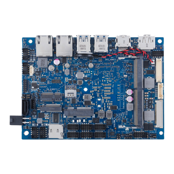
Motherboard Layout
Layout Contents
System Memory
DIMM Slot
Onboard Jumpers
Clear RTC RAM Jumper
Back Light Power Selection Jumper (on Selected Models)
LVDS Panel Power Selection Jumper (on Selected Models)
Back Light Power Enable Jumper (on Selected Models)
HW WDT Enable Jumper
AT/ATX Mode Configuration Jumper
Mini Pcie/Msata Configuration Jumper
Internal Connectors
SATA 6Gb/S & SATA Power Connector
Mini Pcie/Msata Slot
Micro SD Card Slot
Nano SIM Card Slot
Wi-Fi Slot
Chassis Intrusion Connector
Power Button Connector
Battery Connector
Low Pin Count Connector
EDP Signal Connector (on Selected Models)
GPIO Connector
System Management Bus Connector
I2C Connector
SPI TPM Connector
Serial Port Connector
USB 2.0 Connector
Back Light Inverter Power Connector (on Selected Models)
LVDS Connector (on Selected Models)
DC-In 4-Pin Power Connector
Fan Connector (on Selected Models)
System Panel Connector
Line out / MIC Connector
I/O Connectors
Chapter 3: Upgrading Your Single Board Computer
Installing Memory Modules
Installing 2.5" Storage Device
Installing the Mini Pcie or Msata Card
Installing a Nano SIM Card
Installing an SD Card
Installing the Wireless Card
Installing an M.2 SSD
Chapter 4: BIOS Setup
Getting to Know Your BIOS
BIOS Setup Program
Main Menu
System Date [Day XX/XX/XXXX]
System Time [XX:XX:XX]
Advanced Menu
PCH-FW Configuration
Trusted Computing
Platform Misc Configuration
CPU Configuration
System Agent (SA) Configuration
PCH-IO Configuration
PCH Storage Configuration
Onboard Devices Configuration
ACPI Settings
APM Configuration
NCT6116D Super IO Configuration
NCT6116D HW Monitor
Serial Port Console Redirection
USB Configuration
Network Stack Configuration
Nvme Configuration
SDIO Configuration
Security
Boot Menu
Save & Exit Menu
Updating Your BIOS
ASUS Crashfree BIOS 3 Utility
ASUS Ezflash Utility
BUPDATER Utility
Appendix
Safety Information
Setting up Your System
Care During Use
Regulatory Notices
ASUS Contact Information
Advertisement
Quick Links
Download this manual
C785S-IM-AA
C582S-IM-AA
C381S-IM-AA
User Manual
Table of
Contents
Previous
Page
Next
Page
1
2
3
4
5
Advertisement
Chapters
Table of Contents
3
Layout Contents
16
Table of Contents
Need help?
Do you have a question about the C785S-IM-AA and is the answer not in the manual?
Ask a question
Questions and answers
Related Manuals for Asus C785S-IM-AA
Motherboard Asus JUMPERFREE PC133 User Manual
Jumperfree pc133/vc133 133/100/66 mhz fsb socket 370 motherboard (92 pages)
Motherboard Asus CUW-RM User Manual
Intel 810 microatx motherboard (128 pages)
Motherboard Asus E2938 Hardware User Manual
Asus computer hardware user manual (154 pages)
Motherboard Asus Crosshair V User Manual
(190 pages)
Motherboard Asus CROSSHAIR User Manual
Crosshair english edition user's manual (174 pages)
Motherboard Asus CROSSHAIR IV EXTREME User Manual
User guide (172 pages)
Motherboard Asus CROSSHAIR V FORMULA User Manual
Formula series (193 pages)
Motherboard Asus Crosshair V Formula-Z User Manual
(190 pages)
Motherboard Asus CUSL2 User Manual
Intel 815e atx motherboard (128 pages)
Motherboard ASUS CUSL2-C User Manual
Intel 815ep atx motherboard (122 pages)
Motherboard Asus CUW User Manual
Intel 810 atx motherboard (128 pages)
Motherboard ASUS C8HM70-I User Manual
(57 pages)
Motherboard ASUS CUV4X-D User Manual
Jumperfree pc133/vc133 133 mhz fsb agp pro/4x dual socket 370 motherboard (92 pages)
Motherboard Asus CS-B User Manual
(77 pages)
Motherboard Asus CROSSHAIR VI HERO User Manual
(100 pages)
Motherboard Asus CUW-AM Manual
(21 pages)
This manual is also suitable for:
C582s-im-aa
C381s-im-aa
Table of Contents
Print
Rename the bookmark
Delete bookmark?
Delete from my manuals?
Login
Sign In
OR
Sign in with Facebook
Sign in with Google
Upload manual
Upload from disk
Upload from URL


Need help?
Do you have a question about the C785S-IM-AA and is the answer not in the manual?
Questions and answers