Table of Contents
Advertisement
Quick Links
Download this manual
See also:
User Manual
Advertisement
Table of Contents

Related Manuals for Intel NUC8i5INH


Summary of Contents for Intel NUC8i5INH
- Page 1 Intel® NUC Products NUC8i5INH / NUC8i7INH Technical Product Specification Regulatory Models: NUC8IN June 2019 version 003...
- Page 2 The Intel NUC Products NUC8i5INH/NUC8i7INH may contain design defects or errors known as errata that may cause the product to deviate from published specifications. Current characterized errata are documented in the Intel NUC Products NUC8i5INH/NUC8i7INH Specification Update. Revision History Revision...
-
Page 3: Board Identification Information
NUC8i5INHJA HDD kit with power adapter, 16GB Intel® Optane™ Module, 1TB HDD, 8GB LPDDR3-2133 solder-down Memory, Microsoft Windows 10 Home, “Intel® NUC 8 Home, a Mini PC with Windows 10” NUC8i5INHPA SSD kit with power adapter, 256 M.2 SSD, 8GB LPDDR3- 2133 solder-down Memory, Microsoft Windows 10 Home, “Intel®... -
Page 4: Errata
NUC8i7INHPA SSD kit with power adapter, 256GB M.2 SSD, 8GB LPDDR3- 2133 solder-down Memory, Microsoft Windows 10 Home, “Intel® NUC 8 Home, a Mini PC with Windows 10” NUC8i7INHP SSD kit with power adapter, 256GB M.2 SSD, 8GB LPDDR3- 2133 solder-down Memory... -
Page 5: Preface
Intended Audience The TPS is intended to provide detailed technical information about Intel NUC Products NUC8i5INH/NUC8i7INH and their components to the vendors, system integrators, and other engineers and technicians who need this level of information. It is specifically not intended for general audiences. - Page 6 Other Common Notation Used after a signal name to identify an active-low signal (such as USBP0#) Bits per pixel Gigabyte (1,073,741,824 bytes) GBps Gigabytes per second Gbps Gigabits per second Kilobyte (1024 bytes) Kilobit (1024 bits) kbps 1000 bits per second Megabyte (1,048,576 bytes) MBps Megabytes per second...
-
Page 8: Table Of Contents
Contents Revision History ......................iii Note: For this Technical Products Specification, the use of Intel NUC Products NUC8i5INH/NUC8i7INH ........................... iv Board Identification Information ........................iv Product Identification Information ......................... iv Errata .................................... v Preface ..........................vi Intended Audience ..............................vi What This Document Contains ........................ - Page 9 ACPI ............................. 29 1.11.2 Hardware Support ......................... 31 1.11.3 HDMI Consumer Electronics Control (CEC) ..............33 1.12 Intel Platform Security Technologies ....................35 1.12.1 Intel® Virtualization Technology ..................35 1.12.2 Intel® Platform Trust Technology ................... 35 2 Technical Reference ....................37 Memory Resources ..........................
- Page 10 Figure 16. Board Dimensions ..........................46 Figure 17. Board Height Dimensions ......................... 47 Figure 18. Localized High Temperature Zones ..................... 49 Figure 19. Intel® NUC Products NUC8i5INH/NUC8i7INH Features – Front ........61 Figure 20. Intel® NUC Products NUC8i5INH/NUC8i7INH Features – Rear ......... 62 Tables Table 1.
- Page 11 Table 16. Select Weights and ..........................47 Table 17. Select Chassis Dimensions ......................... 47 Table 18. Fan Header Current Capability ......................47 Table 19. Thermal Considerations for Components ................... 50 Table 20. Tcontrol Values for Components ....................50 Table 21. Environmental Specifications ......................51 Table 22.
-
Page 12: Product Description
Table 1 summarizes the major features of the product. Table 1. Feature Summary 4.0 inches by 4.0 inches (101.60 millimeters by 101.60 millimeters) Board Form Factor Soldered-down 8th Generation Intel® Core™ i5 Quad-core Processors with 15W Processor TDP, 1.60 GHz ― TDP-up 25W ―... - Page 13 Consumer Electronics Control (CEC) header Front panel header USB 2.0 ports: ― Two ports via an internal common IO header Gigabit (10/100/1000 Mbps) LAN subsystem using the Intel WGI219V Gigabit Ethernet LAN Support Controller Hardware Monitor Hardware monitoring subsystem, based on an ITE8991VG embedded controller,...
-
Page 14: Board Layout (Top)
Product Description 1.1.2 Board Layout (Top) Figure 1 shows the location of the major components on the top-side of Intel NUC Boards NUC8INB Figure 1. Major Board Components (Top) Table 2 lists the components identified in Figure 1. Table 2. Components Shown in Figure 1... -
Page 15: Board Layout (Bottom)
1.1.3 Board Layout (Bottom) Figure 2 shows the location of the major components on the bottom-side of Intel NUC Mini PC NUC8i5INH/NUC8i7INH. Figure 2. Major Board Components (Bottom) -
Page 16: Table 3. Components Shown In Figure 2
Product Description Table 3. Components Shown in Figure 2 Item from Figure 2 Description 19V DC input jack Back panel USB 3.1 gen2 connectors Mini Display Port HDMI connector LAN jack SDXC card reader slot Front panel single-port USB 2.0 connector (1.25 mm pitch) Front panel single-port USB 2.0 connector (1.25 mm pitch) M.2 connector Front panel USB 3.1 gen2 connector... -
Page 17: Block Diagram
1.1.4 Block Diagram Figure 3 is a block diagram of the major functional areas of the board. Figure 3. Block Diagram... -
Page 18: Online Support
Processor Intel NUC Mini PC NUC8i5INH/NUC8i7INH has a soldered-down System-on-a-Chip (SoC), which consists of one of following: Soldered-down 8th Generation Intel® Core™ i5 Quad-core Processors with 15W TDP, 1.60 GHz TDP-up 25W 6 MB SmartCache, 3.60 GHz Max Turbo Frequency ... -
Page 19: Graphics Capabilities
Graphics Capabilities The kit supports graphics computing through AMD Radeon™ 540X 1.4.1 AMD Radeon™ 540X Graphics The AMD Radeon graphics controller features the following: Supports HDR-10 video playback. Multi View Coding (MVC) support for Blu-ray 3D content. 3D graphics hardware acceleration supporting DirectX 12, OpenCL* 2.0, OpenGL 4.5 ... - Page 20 Product Description DisplayPort. This will require the use of displays that support DisplayPort 1.4 and allow for this feature. For information about Refer to DisplayPort technology http://www.displayport.org...
-
Page 21: Usb
In order to use AHCI mode, AHCI must be enabled in the BIOS. Microsoft* Windows* 10 includes the necessary AHCI drivers without the need to install separate AHCI drivers during the operating system installation process. However, it is always good practice to update the AHCI drivers to the latest available by Intel. -
Page 22: Real-Time Clock Subsystem
Product Description Real-Time Clock Subsystem A coin-cell lithium battery (CR2032) powers the real-time clock and CMOS memory. When the computer is not plugged into a wall socket, the battery has an estimated life of three years. When the computer is plugged in, the standby current from the power supply extends the life of the battery. -
Page 23: Audio Subsystem
Audio Subsystem The product supports Intel HD Audio via the Realtek ALC233 audio codec. The audio subsystem supports the following features: Analog line-out/Analog Headphone/Analog Microphone jack on the front panel High Definition Audio via a stereo microphone/headphone/optical jack on the back panel ... -
Page 24: Lan Subsystem
Full device driver compatibility For information about Refer to Full LAN Hardware feature set http://www.Intel.com/Networking 1.9.2 LAN Subsystem Software LAN software and drivers are available from Intel’s World Wide Web site. For information about Refer to Obtaining LAN software and drivers http://downloadcenter.intel.com... -
Page 25: Rj-45 Lan Connector With Integrated Leds
100 Mb/s data rate is selected. Yellow 1000 Mb/s data rate is selected. 1.9.4 Wireless Network Module The Intel Wireless-AC 9560D2W module provides high performance low power wireless connectivity with the following capabilities: 802.11ac R2, Dual Band, 2x2, Wi-Fi + Bluetooth 5.0 ... -
Page 26: Hardware Management Subsystem
Management (WfM) specification. The board has several hardware management features, including thermal and voltage monitoring. For information about Refer to Wired for Management (WfM) Specification www.intel.com/design/archives/wfm/ 1.10.1 Hardware Monitoring The hardware monitoring and fan control subsystem is based on an ITE IT8987VG embedded controller, which supports the following: ... -
Page 27: Thermal Solution
1.10.3 Thermal Solution Figure 6 shows the location of the thermal solution and processor fan header. Figure 6. Thermal Solution and Fan Header Item Description Thermal Solution Processor fan header... -
Page 28: Power Management
Product Description 1.11 Power Management Power management is implemented at several levels, including: Software support through Advanced Configuration and Power Interface (ACPI) Hardware support: Power Input Instantly Available PC technology LAN wake capabilities Wake from USB ... -
Page 29: Table 6. Power States And Targeted System Power
1.11.1.1 System States and Power States Under ACPI, the operating system directs all system and device power state transitions. The operating system puts devices in and out of low-power states based on user preferences and knowledge of how devices are being used by applications. Devices that are not being used can be turned off. -
Page 30: Hardware Support
Product Description 1.11.1.2 Wake-up Devices and Events Table 7 lists the devices or specific events that can wake the computer from specific states. Table 7. Wake-up Devices and Events Devices/events that wake up the …from this sleep state Comments system… Power switch S3, S4, S5 RTC alarm... - Page 31 1.11.2.1 Power Input When resuming from an AC power failure, the computer may return to the power state it was in before power was interrupted (on or off). The computer’s response can be set using the Last Power State feature in the BIOS Setup program’s Boot menu. 1.11.2.2 Instantly Available PC Technology Instantly Available PC technology enables the board to enter the ACPI S3 (Suspend-to-RAM)
-
Page 32: Hdmi Consumer Electronics Control (Cec)
Product Description CAUTION If AC power has been switched off and the standby power indicator is still lit, disconnect the power cord before installing or removing any devices connected to the board. Failure to do so could damage the board and any attached devices. Figure 7. -
Page 33: Figure 8. Cec Connector
Auto Turn Off TV (S0 -> S5) PC Shutdown TV standby Auto Turn On TV (S5 -> S0) PC On TV on Auto Turn Off TV (S0 -> S3) PC Sleep TV standby Auto Turn On TV (S3 -> S0) PC On TV on Notes:... -
Page 34: Intel Platform Security Technologies
NOTE A processor with Intel VT does not guarantee that virtualization will work on your system. Intel VT requires a computer system with a chipset, BIOS, enabling software and/or operating system, device drivers, and applications designed for this feature. -
Page 36: Technical Reference
Technical Reference Memory Resources 2.1.1 Addressable Memory The board utilizes up to 8 GB of addressable system memory. Typically the address space that is allocated for PCI Conventional bus add-in cards, PCI Express configuration space, BIOS (SPI Flash device), and chipset overhead resides above the top of DRAM (total system memory). On a system that has 8 GB of system memory installed, it is not possible to use all of the installed memory due to system address space being allocated for other system critical functions. -
Page 37: Front Panel Connectors
2.2.1 Front Panel Connectors Figure 9 shows the location of the front panel connectors, controls and indicators for the board. Figure 9. Front Panel Connectors, Controls and Indicators Item Description Power switch and LED Front panel stereo microphone/headphone jack USB 3.1 Gen2 charging-capable port (amber) USB 3.1 Gen 2 USB Type C Hard drive activity LED 2.2.2... -
Page 38: Headers And Connectors (Top)
Technical Reference 2.2.3 Headers and Connectors (Top) Figure 11 shows the location of the headers and connectors on the top-side of the board. Figure 11. Headers and Connectors (Top) Table 9 lists the headers and connectors identified in Figure 11. Table 9. -
Page 39: Connectors And Headers (Bottom)
2.2.4 Connectors and Headers (Bottom) Figure 12 shows the locations of the connectors and headers on the bottom-side of the board. Figure 12. Connectors and Headers (Bottom) -
Page 40: Table 10. Connectors And Headers Shown In Figure 12
Technical Reference Table 10 lists the connectors and headers identified in Figure 12. Table 10. Connectors and Headers Shown in Figure 12 Item from Figure 12 Description SDXC slot Front panel single-port USB 2.0 header (USB1/USB2) (1.25 mm B, C pitch) M.2 connector SATA 6.0 Gb/s connector... -
Page 41: Table 12. Single-Port Internal Usb 2.0 Headers (1.25 Mm Pitch)
Table 12. Single-Port Internal USB 2.0 Headers (1.25 mm Pitch) Signal Name Data (positive) Data (negative) +5 V DC NOTE Use only an internal USB connector that conforms to the USB 2.0 specification for high-speed USB devices. Table 13. Consumer Electronics Control (CEC) Connector (1.25 mm Pitch) Signal Name +5VSB Ground... -
Page 42: Figure 14. Location Of The Cir Sensor
Microsoft CIR specifications. Customers are required to provide their own media center compatible remote or smart phone application for use with the Intel NUC. Figure 13 shows the location of the CIR sensor. Figure 13. Location of the CIR Sensor... -
Page 43: Bios Security Jumper
BIOS Security Jumper CAUTION Do not move a jumper with the power on. Always turn off the power and unplug the power cord from the computer before changing a jumper setting. Otherwise, the board could be damaged. Figure 14 shows the location of the BIOS security jumper. The 3-pin jumper determines the BIOS Security program’s mode. -
Page 44: Table 15. Bios Security Jumper Settings
Technical Reference Table 15. BIOS Security Jumper Settings Function/Mode Jumper Setting Configuration Normal The BIOS uses current configuration information and passwords for booting. Lockdown The BIOS uses current configuration information and passwords for booting, except: • All POST Hotkeys are suppressed (prompts are not displayed and keys are not accepted. -
Page 45: Mechanical Considerations
Mechanical Considerations 2.4.1 Form Factor The board is designed to fit into a custom chassis. Figure 15 illustrates the mechanical form factor for the board. Dimensions are given in millimeters. The outer dimensions are 101.60 millimeters by 101.60 millimeters [4.0 inches by 4.0 inches]. Figure 15. -
Page 46: Weight
Technical Reference Figure 16 shows the height dimensions of the board. Figure 16. Board Height Dimensions 2.4.2 Weight Error! Reference source not found. lists select weights of boards and kits and Table 17 lists kit dimensions. Table 16. Select Weights and Item Weight (in kg) Board with Thermal Solution... -
Page 47: Thermal Considerations
All responsibility for determining the adequacy of any thermal or system design remains solely with the system integrator. Intel makes no warranties or representations that merely following the instructions presented in this document will result in a system with adequate thermal performance. -
Page 48: Figure 18. Localized High Temperature Zones
Technical Reference Figure 17. Localized High Temperature Zones Item Description Thermal solution Processor voltage regulator area... -
Page 49: Table 19. Thermal Considerations For Components
Table 19 provides maximum case temperatures for the components that are sensitive to thermal changes. The operating temperature, current load, or operating frequency could affect case temperatures. Maximum case temperatures are important when considering proper airflow to cool the board. Table 19. -
Page 50: Reliability
Technical Reference Reliability The Mean Time Between Failures (MTBF) prediction is calculated using component and subassembly random failure rates. The calculation is based on the Telcordia SR-332-2 Issue 2, Method I, Case 3, 55⁰C ambient. The MTBF prediction is used to estimate repair rates and spare parts requirements. -
Page 52: Overview Of Bios Features
Overview of BIOS Features Introduction The board uses an Intel NUC BIOS that is stored in the Serial Peripheral Interface Flash Memory (SPI Flash) and can be updated using a disk-based program. The SPI Flash contains the BIOS Setup program, POST, the PCI auto-configuration utility, LAN EEPROM information, and Plug and Play support. -
Page 53: Legacy Usb Support
USB drive (a flash drive or a USB hard drive). Intel F7 switch during POST allows a user to select where the BIOS .CAP file is located and perform the update from that location/device. Similar to performing a BIOS Recovery without removing the BIOS configuration jumper. -
Page 54: Language Support
Overview of BIOS Features 3.5.1 Language Support The BIOS Setup program and help messages are supported in US English. Check the Intel web site for support. BIOS Recovery It is unlikely that anything will interrupt a BIOS update; however, if an interruption occurs, the BIOS could be damaged. -
Page 55: Booting Without Attached Devices
Pressing the <F12> key during POST automatically forces booting from the LAN. To use this key during POST. 3.7.2 Booting Without Attached Devices For use in embedded applications, the BIOS has been designed so that after passing the POST, the operating system loader is invoked even if the following devices are not present: ... -
Page 56: Power Button Menu
Overview of BIOS Features 3.7.4 Power Button Menu The Power Button Menu is accessible via the following sequence: 1. System is in S4/S5 (not G3) 2. User pushes the power button and holds it down 3. The power LED will change to its secondary color to signal the user to release the power button (approximately 3 seconds) then stop. -
Page 57: Hard Disk Drive Password Security Feature
Hard Disk Drive Password Security Feature The Hard Disk Drive Password Security feature blocks read and write accesses to the hard disk drive until the correct password is given. Hard Disk Drive Passwords are set in BIOS SETUP and are prompted for during BIOS POST. For convenient support of S3 resume, the system BIOS will automatically unlock drives on resume from S3. -
Page 58: Table 25. Supervisor And User Password Functions
Overview of BIOS Features If both the supervisor and user passwords are set, users can enter either the supervisor password or the user password to access Setup. Users have access to Setup respective to which password is entered. Setting the user password restricts who can boot the computer. -
Page 59: Error Messages And Blink Codes
Error Messages and Blink Codes Front-panel Power LED Blink Codes Whenever a recoverable error occurs during POST, the BIOS causes the board’s front panel power LED to blink an error message describing the problem (see Table 26). Table 26. Front-panel Power LED Blink Codes Type Pattern Note... -
Page 60: Intel Nuc Kit Features
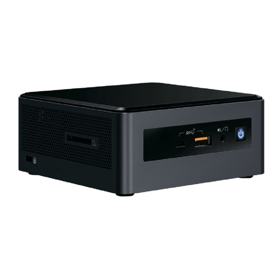
Chassis Front Panel Features Intel NUC Boards NUC8INB can be found integrated into Intel® NUC Mini PC NUC8i5INH/NUC8i7INH. Figure 18 shows the location of the features located on or near the front of the chassis. Figure 18. Intel® NUC Products NUC8i5INH/NUC8i7INH Features – Front Table 27 lists the components identified in Figure 18. -
Page 61: Chassis Rear Panel Features
Chassis Rear Panel Features Figure 19 shows the location of the features located on the rear of the chassis. Figure 19. Intel® NUC Products NUC8i5INH/NUC8i7INH Features – Rear Table 28 lists the components identified in Figure 19. Table 28. Components Shown in Figure 19...
Need help?
Do you have a question about the NUC8i5INH and is the answer not in the manual?
Questions and answers