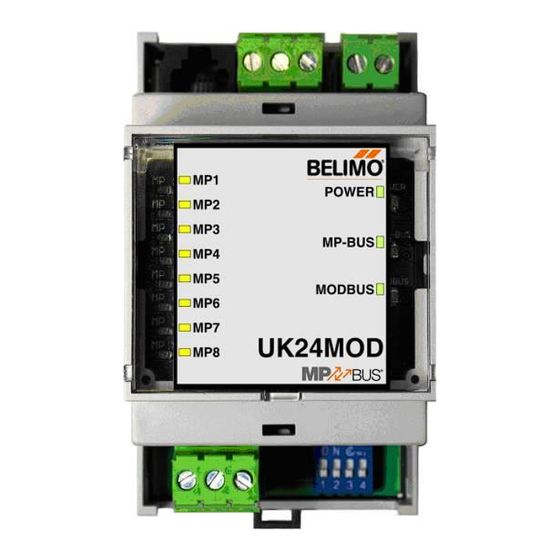
Summary of Contents for Belimo UK24MOD
-
Page 1: Table Of Contents
Operation elements Operation, behaviour Modbus register overview Modbus register description Diagnostics and testing tool Connecting the PC-Tool for parameterisation of the MP/MFT(2) actuators Version overview T9-UK24MOD • en • v1.7 • 02.2014 • Subject to changes www.belimo.com 1 / 20... -
Page 2: Complete Overview
Gateway MP / Modbus RTU Suitable MP/MPL/MFT(2) Actuators Damper actuators Fire damper actuators VAV actuators Actuators for characterised control valve, butterfly valves EPIV actuators and globe valves MPL Actuators T9-UK24MOD • en • v1.7 • 02.2014 • Subject to changes 2 / 20 www.belimo.com... -
Page 3: Technical Data
Installation / Dimension / Weight Mounting Control cabinet installation, can be snapped onto top hat rail 35 mm Dimensions see page 7 Weight ca. 100 g T9-UK24MOD • en • v1.7 • 02.2014 • Subject to changes www.belimo.com 3 / 20... -
Page 4: Safety Notes
Product features Mode of operation The UK24MOD allows the actuators to be controlled digitally via the MP-Bus and send back their current operating status. The control system information and the response is administered in registers in the UK24MOD and can be processed with Modbus commands. This permits the actuator functions to be integrated directly into the Modbus. -
Page 5: Electrical Installation
L = max. cable length [m] With AC 24 V supply: Maximum signal conductor length UK24MOD With AC 24 V supply: Total dimensioning MP/MPL/MFT(2) actuators [VA] Power rating [VA] T9-UK24MOD • en • v1.7 • 02.2014 • Subject to changes www.belimo.com 5 / 20... - Page 6 The signal conductor lengths can be significantly increased if the actuators are supplied with AC Maximum signal conductor length 24 V locally via a separate transformer. The signal conductor lengths indicated in the table apply regardless of the performance data of the actuators connected to the UK24MOD. Wire-Ø L = max. cable length [mm²]...
-
Page 7: Dimensions
Total power rating 3.5 W + 4 W + 3 W + 3 W = 13.5 W [mm²] 0.75 1.00 1.50 2.50 Dimensions Dimensional drawings [mm] T9-UK24MOD • en • v1.7 • 02.2014 • Subject to changes www.belimo.com 7 / 20... -
Page 8: Operation Elements
The Modbus address is set in binary form with the 8 DIP switches under the front cover. The Setting the Modbus address valid address range is 1-247. Values outside of this range will be interpreted as either 1 or 247, respectively. T9-UK24MOD • en • v1.7 • 02.2014 • Subject to changes 8 / 20 www.belimo.com... - Page 9 2 stop bits) or EVEN parity (1 start bit, 8 data bits, even parity, 1 stop bit), The setting is done with DIP switch 4. Important: The generally valid guidelines for RS485 / Modbus RTU are to be observed! T9-UK24MOD • en • v1.7 • 02.2014 • Subject to changes www.belimo.com 9 / 20...
- Page 10 LEDx. Afterwards, the Gateway will switch to standard operation. The addressing process can be interrupted at any time by pressing the OK key. The de-addressing of a node is not supported. T9-UK24MOD • en • v1.7 • 02.2014 • Subject to changes 10 / 20 www.belimo.com...
-
Page 11: Modbus Register Overview
The MP-Bus assignment is determined automatically and updated. The Actuator type register (12) should be evaluated for the monitoring of a node. T9-UK24MOD • en • v1.7 • 02.2014 • Subject to changes www.belimo.com 11 / 20... - Page 12 Modbus address registers register 161 – 164 for service information. Response delay [ms] 1003 1004 Firmware Version The response delay (Register 1003) is backed up continuously. T9-UK24MOD • en • v1.7 • 02.2014 • Subject to changes 12 / 20 www.belimo.com...
-
Page 13: Modbus Register Description
Relative volumetric flow This value is available only for VAV controllers and EPIV units (Actuator Type: 5). For all other types, 65535 will be entered. T9-UK24MOD • en • v1.7 • 02.2014 • Subject to changes www.belimo.com 13 / 20... - Page 14 Function not available for actuator type Time exceeded (fire & smoke only) The malfunction bits can be reset with Register 3 (command: 4) or with the Belimo PC-Tool. Malfunctions 0 and 4 cannot be reset. The error bits will be reset automatically by the Gateway.
- Page 15 The response delay must be increased in the event that the Modbus Master is unable to switch quickly enough from transmission to reception mode. Firmware Version of the device Service register 1004 (former 164): Firmware Version T9-UK24MOD • en • v1.7 • 02.2014 • Subject to changes www.belimo.com 15 / 20...
-
Page 16: Diagnostics And Testing Tool
The MP network can be scanned, actuators can be addressed and actuator-specific parameters (e.g. running time) can be readily adjusted with the Belimo PC-Tool. The PC -Tool can be accessed directly on the MP-Bus via the RJ12 socket of the UK24MOD. The Gateway recognises the connected PC-Tool automatically and stops communications with the MP drives. -
Page 17: Version Overview
New functions: Parity/Character transmission adjustable via DIP switch: NONE (1, 8, N, 2) or EVEN (1, 8, E, 1) Firmware V1.03 Release without restrictions T9-UK24MOD • en • v1.7 • 02.2014 • Subject to changes www.belimo.com 17 / 20... - Page 18 UK24MOD Belimo Gateway MP to Modbus RTU T9-UK24MOD • en • v1.7 • 02.2014 • Subject to changes 18 / 20 www.belimo.com...
- Page 19 UK24MOD Belimo Gateway MP to Modbus RTU T9-UK24MOD • en • v1.7 • 02.2014 • Subject to changes www.belimo.com 19 / 20...


Need help?
Do you have a question about the UK24MOD and is the answer not in the manual?
Questions and answers