
Related Manuals for SkyWave SG-7100

Summary of Contents for SkyWave SG-7100
- Page 1 SG-7100 Hardware Guide T300, Version 01 The electronic version of this document allows you to use the built-in Hyperlinks and bookmarks when using Adobe Reader © SkyWave Mobile Communications Inc. Nov 2014...
-
Page 2: Legal Notice
This documentation is provided on an as-is basis without any warranty of any kind. You assume the entire risk as to the results or performance of the software. Under no circumstance shall SkyWave be held liable for any direct, indirect, consequential, or incidental damages arising from the use or inability to use the software or documentation. -
Page 3: Table Of Contents
SG-7100 - Hardware Guide TABLE OF CONTENTS Legal Notice ............................ ii Contact Information ........................ii List of Figures ..........................vi List of Tables ..........................vii Preface ............................ix Purpose ............................ix Audience ............................ix Errata Sheet ..........................ix Notation ............................ix Reference ............................. - Page 4 Connect to Power ......................36 3.10 Route the Main Cable ....................... 36 3.11 Protect the Cables and Power Connector ................. 37 3.12 Configure and Register the SG-7100 ................37 Compliance ........................38 APPENDIX A Orderable Part Numbers ................39 APPENDIX B IDP Power and Serial Cable Pin-out ............. 40 Revision History ..........................
- Page 5 SG-7100 - Hardware Guide Acronyms/Glossary ........................42 Index… ............................43 © SkyWave Proprietary T300, Version 01...
-
Page 6: List Of Figures
Simplex Serial Expansion Card ................. 18 Figure 19 Simplex Serial Expansion Card RS-232 Serial Connector (female) ......18 Figure 20 SG-7100 Connected with a DTE Device ..............19 Figure 21 SG-7100 Connected with a DCE Device ..............19 Figure 22 Industrial Expansion Card .................. - Page 7 Power Connector Pin-out (facing view of cable connector) ......... 8 Table 3 Accelerometer Power Consumption Factors ..............9 Table 4 Supported Sleep Phase Durations................10 Table 5 SG-7100 Mass and Materials ..................12 Table 6 LED Descriptions ......................13 Table 7 Ethernet LEDs ......................14 Table 8 Pin-out of Serial Connector ..................
- Page 8 SG-7100 - Hardware Guide THIS PAGE INTENTIONALLY LEFT BLANK T300, Version 01 viii © SkyWave Proprietary...
-
Page 9: Preface
SG-7100. Errata Sheet Refer to the SkyWave Customer Support website for a possible Errata Sheet available after the release of this document. Always check the site for the most current documentation releases. -
Page 10: Safety Disclaimer
Safety Precautions The terminal must comply with all safety precautions relating to the operation, usage, service and repair of the terminal. SkyWave assumes no liability for the customer's failure to comply with any of these precautions. Caution warnings appear throughout this document. -
Page 11: Limited Liability
SkyWave's directors, officers, employees, agents and assigns and for such purposes SkyWave is or shall be deemed to be acting as agent or trustee on behalf of and for the benefit of such companies and persons. - Page 12 SG-7100 - Hardware Guide THIS PAGE INTENTIONALLY LEFT BLANK T300, Version 01 © SkyWave Proprietary...
-
Page 13: Product Overview
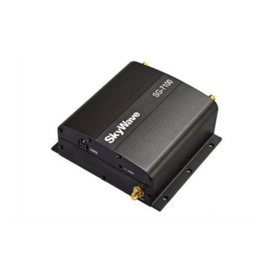
Figure 1 SG-7100 The fully programmable SG-7100 allows you to create your own applications through the use of Lua and open Linux development environments, and supports multiple LAN and WAN interfaces along with providing an onboard web server. -
Page 14: Sg-7100 Components
RS-232/RS-485 or 2 x RS-232 USB (OTG and Host) 1-Wire Dual SIM slots SG-7100 Components Each SG-7100 consists of the following components, excluding interconnecting cabling: Base Unit Expansion Cards (optional) Antennas (optional) Software Bundles 1.2.1... -
Page 15: Front Panel
Use a small screwdriver or pen to press and hold the reset button for less than 5 seconds to reset the SG-7100 to the last working setting (normal reset). Press and hold for 5 seconds or more to reset the SG-7100 to factory settings. -
Page 16: Expansion Cards
1.2.2 Expansion Cards Several expansion cards are available to expand the capabilities of the SG-7100. A total of two optional expansion cards can be installed. Expansion cards are built specifically for the front and back panels and they are not interchangeable. -
Page 17: Industrial Expansion Card
Cellular Antenna The Cellular antenna (ST100304-001) (Figure 9) is a Penta-band 3G cellular antenna. It supports all of the cellular bands used by the SG-7100. This antenna is connected to the SG-7100 antenna connector labeled, "WWAN Main" on the base unit. -
Page 18: Cellular Plus Gps Antenna
The WLAN/Wi-Fi fixed antenna (ST100304-004) (Figure 11) supports the 2.4 GHz band used by the SG-7100's optional WLAN expansion card. This antenna is fixed at 90° and connects to the antenna connector on the expansion card, which is labeled, "WLAN Main". -
Page 19: Software Bundles
Software Bundles To extend the functionality provided by the firmware, you can install software bundles that adapt the SG-7100 to your specific needs. Software bundles can be created for custom applications and middleware, and to control third-party expansion cards. For additional information refer to [T302] or contact SkyWave Customer Support. -
Page 20: Specifications
Optional load dump protection on the power connector is available and strongly recommended for all installations in heavy-duty vehicles or any installation where load dump might occur. SkyWave provides a cable (ST100334-001) with load dump protection to the specifications as per SAE J1455 to 24V. 2.2.1.2 Base Unit Internal Power Supply ... -
Page 21: Sim Card Holders
2.2.2 SIM Card Holders The SG-7100 base unit provides a single SIM card slot. The optional Telematics expansion card offers two additional SIM card slots. The specifications for both are the same. If only using one SIM card, use the main base unit SIM card holder. If using multiple SIM cards, both cards should be installed in the Telematics card. -
Page 22: Processor And Operating System
SG-7100 - Hardware Guide Parameter Description consumption. Setting up multiple thresholds with multiple durations which require post processing keep the accelerometer and CPU running longer. Table 4 shows the supported sleep phase durations and their impact on current draw at 12 VDC. -
Page 23: Physical Details
SG-7100 - Hardware Guide Physical Details All dimensions are shown in millimeters (mm). Refer to section 2.9 for antenna dimensions. Figure 13 SG-7100 Side View Dimensions (mm) Figure 14 SG-7100 Top View Dimensions (mm) © SkyWave Proprietary T300, Version 01... -
Page 24: Ethernet Interface
In order for auto-MDIX to work correctly, auto-negotiation (auto speed and auto duplex) must be enabled on both sides of the link. Status Indicators The SG-7100 has a number of LEDs (Figure 16) to indicate status and signal strength as shown in Table 6. Figure 16 LEDs T300, Version 01 ©... -
Page 25: Table 6 Led Descriptions
SG-7100 - Hardware Guide Table 6 LED Descriptions Description WLAN State Indicates the connection status of the WLAN interface. Off: Not installed Orange: WLAN board = OK, client not connected and AP not enabled Orange blinking: AP disabled and client connected/data traffic... -
Page 26: Wwan (Cellular) Interface
WCDMA bands: I, II, IV, V, VI, VII CDMA bands: BC0,1 2.10 GPS The SG-7100 has an integrated GPS receiver. If connected to an optional IDP terminal, the GPS from the IDP terminal can also provide GPS information as well as GLONASS connectivity. ... -
Page 27: 2.12 Antennas
SG-7100 - Hardware Guide 2.12 Antennas 2.12.1 Cellular Antenna Parameter Value HSPA Penta-Band 800/850/1800/1900/2100 MHz diversity capability. Fallback to HSDPA/UMTS/EDGE/GPRS EV-DO Rev A Dual- 800/1900 MHz diversity capability. Band Fallback to CDMA 1x Rev 0 and CDMA 1xRTT Communication GSM-... -
Page 28: Wlan (Wi-Fi) Antenna
SG-7100 - Hardware Guide 2.12.3 WLAN (Wi-Fi) Antenna Hinged Parameter Value Frequency 2.4 ~ 2.5 GHz 5.15 ~ 5.85 GHz Peak Gain 2.37 dBi 2.93 dBi Average Gain -1.21 dBi -1.32 dBi Efficiency 50 Ω Impedance Polarization Linear Vertical Radiation... -
Page 29: 2.13 Expansion Cards - Serial Interfaces
United States. Note: The WLAN/Wi-Fi card has its own SSID/WPA2 password sticker which ships with the card. Ensure you attach the sticker to the underside of the SG-7100 base unit. The WLAN/Wi-Fi expansion card includes the following features: ... -
Page 30: Simplex Serial Expansion Card
SG-7100 - Hardware Guide 2.13.2 Simplex Serial Expansion Card The Simplex Serial expansion card is a DCE device with a DB9 connector. It has a single RS-232 serial port with a maximum speed of 921.6 Kb. Figure 18 Simplex Serial Expansion Card... -
Page 31: Industrial Serial Card
SG-7100 - Hardware Guide Use a regular straight cable when connecting this port to a laptop or any other DTE device. Figure 20 SG-7100 Connected with a DTE Device SG-7100 Laptop (DCE) (DTE) Use a crossover cable (= null modem cable) when connecting the port to another DCE device. -
Page 32: Figure 23 Industrial Serial Card Rs-232 Serial Connector Pin-Out (Female)
SG-7100 - Hardware Guide Interface Parameters 921.6 Kb maximum speed RS-232 DB9 connector 921.6 Kb maximum speed RS-485 Full duplex or half duplex 5-pin Phoenix connector (MC 1.5/5ST-3.81) Termination switch - to terminate the RS-485 network with a 120 Ohm resistor... -
Page 33: Telematics Card
SG-7100 - Hardware Guide 2.13.4 Telematics Card Figure 24 Telematics Card The Telematics expansion card offers the following features: USB1: USB on-the-go (OTG) interface on micro-AB type connector that supports both host and device configurations USB2: USB host interface on Type-A connector ... -
Page 34: Figure 25 Rs-232 Connector (Male)
SG-7100 - Hardware Guide 2.13.4.1 RS-232 The RS-232 connector is a male DB9 DTE connector. Figure 25 RS-232 Connector (male) Pin 9 Pin 6 Pin 1 Pin 5 Table 11 Pin-out of RS-232 Serial Connector (male) Signal Signal Name Data Carrier Detect... -
Page 35: Input/Output
The external I/Os are available on an 18-pin Molex Micro-Fit 3.0™ connector, labelled as "GPIO" on the front panel. Please refer to the cgio service (SIN 61) in [T301] for details on programming the input/outputs. The SG-7100 does not support temperature and power analog inputs. -
Page 36: Table 14 Digital Inputs (Input1 To Input5)
SG-7100 - Hardware Guide Digital Inputs Table 14 Digital Inputs (Input1 to Input5) Condition Min. Max. Unit Input Voltage Maximum operational Absolute maximum Low Input Voltage 1.05 High Input Voltage 1.88 Input Leakage Current 0.0-3.3 V ± 0.1 > 3.3 V <... -
Page 37: Default Jumpers Configuration
SG-7100 - Hardware Guide Digital Outputs Table 17 Digital Outputs (Output8, Output9, Output13 and Output14) Mode Parameter Condition Min. Max. Unit Push-pull Low level output Open circuit voltage Current sink < 8 mA High level output Open circuit voltage Current sources < 8 mA... -
Page 38: Rs-485 Jumper Configuration
SG-7100 - Hardware Guide The SG-7100 default configuration is: 3 outputs (output8, output13, and output14) 4 digital inputs (input1, input2, input3 and input5) 2 analog inputs (input6 and input7) 1-Wire (requires output12) 3-wire RS-232 (requires input4 and output9 - Table 18) ... -
Page 39: Accelerometer Operating Modes
SG-7100 - Hardware Guide The accelerometer thresholds to detect motion vary depending on the environment. In order to avoid false motion detects, extensive testing is required to ensure that adequate acceleration magnitude thresholds and time durations are used. Parameter Condition... -
Page 40: Sampling Rates
SG-7100 - Hardware Guide Operating Mode Description configured sample rate. Active mode is entered when sample capturing is active or detectors are enabled and the sleepDuration (PIN 3) is zero. The accelerometer supports the following gravity compensation modes: None In this mode (the default) there is no compensation with respect to gravity performed by the API. -
Page 41: Installation
Refer to Preface section for details. Getting Started Getting the SG-7100 ready for operation requires doing the following: 1. Prepare for the installation (Section 3.2) 2. Install the SIM (optional) (Section 3.3) 3. Install expansion cards (optional) (Section 3.4) 4. -
Page 42: Mobile Id
3.2.3 Mobile ID Each SG-7100 has a unique mobile ID to register it on the IsatData Pro network. The mobile ID is located on the SkyWave label on the bottom of the SG-7100 below the barcode. This is a 15-digit alphanumeric identifier in the format NNNNNNNNSKYXXXX. -
Page 43: Insert A Single Sim Card
SG-7100 - Hardware Guide 3.3.1 Insert a Single SIM Card Ensure you have an activated SIM card with a cellular data plan from your solution provider before continuing. 1. Disconnect any power to the unit. 2. Use a T6 Torx screwdriver to remove the four screws from the panel containing the power connector and reset button (Figure 29). -
Page 44: Insert Multiple Sim Cards
SG-7100 - Hardware Guide Figure 31 Insert SIM Card Notch 5. Replace the panel on the SG-7100 and use the T6 screwdriver to tighten the four screws. 3.3.2 Insert Multiple SIM Cards Remember to follow standard ESD guidelines when handling expansion cards. -
Page 45: Install Expansion Cards (Optional)
Note: Expansion cards must be configured once they are installed in the base unit and before the unit is mounted. SkyWave offers various expansion cards (Section 1.2.2) for use with the SG-7100. Expansion cards are designed to fit into one of the two expansion slots accessed from the unit's front or back panels. -
Page 46: Determine A Suitable Mounting Location
20 cm away from humans. CAUTION Most users install the SG-7100 on a vehicle. It is very important for installers to install the units in a safe and secure way to avoid danger or damage to persons or property. -
Page 47: Mount The Sg-7100
SG-7100 - Hardware Guide Mount the SG-7100 3.7.1 Required Materials You require the following materials to install an SG-7100. These do not ship with the unit. 6 x #8 pan head screws (length is determined by mounting surface) ... -
Page 48: Connect An Idp Terminal (Optional)
2. Use the SG-7100 flanges as a template to mark the six holes with a pencil on the mounting surface. 3. Drill the 6 x 4.3 mm holes. Do not drill into the SG-7100 housing. -
Page 49: 3.11 Protect The Cables And Power Connector
Route the cable starting from the unit to the power source. Note: SkyWave recommends that you tape cable ends to prevent dirt from collecting on the contacts. 3.11 Protect the Cables and Power Connector... -
Page 50: Compliance
SG-7100 - Hardware Guide Compliance The SG-7100 has the following certifications: Industry Canada RSS-170, Issue 2, Spectrum Management and Telecommunications Policy, Radio Standard FCC Part 15 CFR Title 47: Telecommunication, Part 15 FCC Part 25 CFR Title 47 ... -
Page 51: Appendix A Orderable Part Numbers
SG-7100 - Hardware Guide Orderable Part Numbers APPENDIX A Table 22 Orderable Part Numbers Units Part Number SG-7100 base unit (AMERICAS) includes SM201340-001 SG-7100 base unit (EMEA) includes SM201340-002 Antennas Part Number Cellular antenna ST100304-001 Cellular/GPS antenna ST100304-002 WLAN/Wi-Fi antenna (hinged) ST100304-003 WLAN/Wi-Fi antenna (fixed at 90°) -
Page 52: Appendix B Idp Power And Serial Cable Pin-Out
SG-7100 - Hardware Guide IDP Power and Serial Cable Pin-out APPENDIX B The IDP power and serial cable (ST100333-001) has the pin-outs shown in Table 23. Figure 37 IDP Power and Serial Cable Table 23 Wiring Chart Connector Face Flying Leads... -
Page 53: Revision History
SG-7100 - Hardware Guide Revision History Version Date Details Nov 2014 Initial customer release Certificação Anatel Representante no Brasil: ORBCOMM do Brasil Telecomunicações Ltda. Rua João XXIII, 153, AP. 02, Rincão dos Ilhéus Estância Velha, RS – 93600.00 - Brasil Tel.: +55 51 9515 3417... -
Page 54: Acronyms/Glossary
SG-7100 - Hardware Guide Acronyms/Glossary direct current data circuit-terminating equipment data terminal equipment Electrostatic Discharge Federal Communications Commission Global System for Mobile Communications ground general purpose input/output GPIO GPRS general packet radio service Global Positioning System High Speed Packet Access... -
Page 55: Index
SG-7100 - Hardware Guide Index… accelerometer jumper settings sampling rates ........28 defulat ........... 25 sleep phase duration ......10 RS-232 ..........25 antenna RS-485 ..........26 cellular ..........3, 15 LED ............12 cellular/GPS ........3, 15 location ........... 3 models ............. - Page 56 www.SkyWave.com...
Need help?
Do you have a question about the SG-7100 and is the answer not in the manual?
Questions and answers