Table of Contents
Advertisement
Advertisement
Chapters
Table of Contents

Subscribe to Our Youtube Channel
Related Manuals for Baumuller b maXX 5500

Summary of Contents for Baumuller b maXX 5500
- Page 1 Instruction handbook English Language Translation Document No. 5.13008.10 Part No. 446684 Status 22-May-2019 b maXX 5500 BM5500 BM5600 BM5700 Basic Units/ Power Modules with Servo Controller Read the Instruction handbook before starting any work! 5.13008.10...
- Page 2 Copyright These Instruction handbook may be copied by the owner in any quantity, but only for internal use. This Instruction handbook may not be copied or reproduced, in whole or in part, for any other purposes. The use and disclosure of information contained in these Instruction handbook are not per- mitted....
-
Page 3: Table Of Contents
Table of Contents General ..............Information on the instruction handbook . - Page 4 Table of Contents Electrical data basic units..........61 3.4.1 Electrical data BM55XX universal units .
- Page 5 Table of Contents Installation ............. 159 Safety notes .
- Page 6 Table of Contents 11 Accessories and Spare Parts ..........245 11.1 Cabling .
-
Page 7: General
ENERAL Information on the instruction handbook These instruction handbook provides important information on handling the device. A pre- requisite for safe work is compliance with all specified safety notes and procedural in- structions. Additionally, the valid accident prevention regulations and general safety regulations ap- plicable to the scope of application the device must be complied with. -
Page 8: Limitation Of Liability
Limitation of liability CAUTION! ..points out a potentially dangerous situation that could lead to minor or slight inju- ries if not avoided. NOTICE! ..points out a potentially dangerous situation that could lead to material damage if not avoided. Recommendation NOTE! ..highlights useful tips and recommendations, as well as information for efficient and problem-free use. -
Page 9: Copyright Protection
General Copyright protection The instruction handbook must be treated confidentially. It is to be used exclusively by personnel who work with the device. The consignment of the instruction handbook to third persons without the written permission of the manufacturer is prohibited. NOTE! The specific contents, text, drawings, images and other representations are copy- righted and subject to industrial property rights. -
Page 10: Spare Parts
Spare parts Spare parts WARNING! False or flawed spare parts can lead to damage, malfunction or complete fail- ure, thus endangering safety. Therefore: m Only use original spare parts of the manufacturer. Procure spare parts through an authorized dealer or directly from the manufacturer. Refer to ZAccessories and Spare Parts–... -
Page 11: List Of Other Applicable Documents
Doc.-No. Part No. Part No. German English Instruction handbook b maXX 5000, 5100, 5300 5.09021 439682 439682 Instruction handbook b maXX 5500, 5600, 5700 5.13008 446683 446684 Instruction handbook b maXX 5800 5.16027 464134 464136 Parameter manual Doc.-No. Part No. - Page 12 1.11 List of other applicable documents Instruction handbook b maXX BM5500, BM5600, BM5700 Document No.: 5.13008.10 Baumüller Nürnberg GmbH of 314...
-
Page 13: Safety
AFETY This section provides an overview of all of the important safety aspects for optimum pro- tection of personnel as well as for the safe and problem-free operation. Contents of the instruction handbook Each person who is tasked with performing work on or with the device must have read and understood the instruction handbook before working with the device. -
Page 14: Usage For The Intended Purpose
Usage for the intended purpose Usage for the intended purpose The device is conceived and constructed exclusively for usage compliant with its intended purpose described in these instruction handbook. The devices of the model series BM5500, BM5600, BM5700 are either mains rectifier or active mains rectifier in combination with power modules with servo controller. -
Page 15: Risk Assessment According Eu Directive
Safety Risk assessment according EU Directive Check the quality of the earth connection: Earth current - before connecting the device to the power supply for the first time and - within the recommended service intervals Requirements: m Cross section of the grounding cable according EN 61800-5-1 m Note the required torque of connection! m Grounded mounting plate made of metal m Mains filter, device and shielding of the motor cable are on the same HF potential... -
Page 16: Wiring Of The Power Cables
Risk assessment according EU Directive Mounting Unprotected hands can be injured at the sharp edges of the device. m Wear safety gloves! Unprotected eyes can be injured by thrown up metal particles caused by drilling or making cut-outs. m Wear safety glasses! Short-circuit in In case of a short-circuit high current flows. -
Page 17: Responsibility Of The Operating Company
Safety Responsibility of the operating company The device will be used in commercial areas. Thus, the proprietor of the device is subject to the legal work safety regulations. Along with the notes on work safety in these instruction handbook, the safety, accident prevention and environmental protection regulations valid for the area of application of this device must be complied with. -
Page 18: Training Of The Personnel
Training of the personnel Training of the personnel WARNING! Risk of injury due to insufficient qualifications! Improper handling can lead to significant personal injury and material damage. Therefore: m Certain activities can only be performed by the persons stated in the respective chapters of these instruction handbook. -
Page 19: Personal Protective Equipment
Safety Personal protective equipment The wearing of personal protective equipment is required when working in order to mini- mize health and safety risks. m The protective equipment necessary for each respective type of work shall always be worn during work. m The personal safety signs present in each working area must be observed. -
Page 20: Special Hazards
Special hazards Special hazards In the following section, the remaining marginal risks will be stated that have been iden- tified as a result of the hazard analysis. Observe the safety notes listed here and the warning notes in the further chapters of this Instruction handbook to reduce health risks and dangerous situations. -
Page 21: Fire Fighting
Safety Moving compo- nents WARNING! Risk of injury from moving components! Rotating components and/or components moving linearly can result in severe injury. Therefore: m Do not touch moving components during operation. m Do not open any covering during operation. m The amount of residual mechanical energy depends on the application. Powered components still turn/move for a certain length of time even after the power supply has been switched off. -
Page 22: Safety Equipment
2.11 Safety equipment 2.11 Safety equipment WARNING! Risk of fatal injury due to non-functional safety equipment! Safety equipment provides for the highest level of safety in a facility. Even if safety equipment makes work processes more awkward, under no circumstances may they be circumvented. -
Page 23: Signs And Labels
Safety 2.13 Signs and labels The following symbols and information signs are located in the working area. They refer to the immediate vicinity in which they are affixed. WARNING! Risk of injury due to illegible symbols! Over the course of time, stickers and symbols on the device can become dirty or oth- erwise unrecognizable. - Page 24 2.13 Signs and labels CAUTION! Risk of injury due to hot surface! Therefore: m Wear protective gloves NOTE! When in operation, the top of the device can heat up to temperatures > 70 °C! Instruction handbook b maXX BM5500, BM5600, BM5700 Document No.: 5.13008.10 Baumüller Nürnberg GmbH of 314...
-
Page 25: Signs And Labels Bm5X3X
Safety Figure 2: Signs and labels BM5X3X Instruction handbook b maXX BM5500, BM5600, BM5700 Document No.: 5.13008.10 of 314... -
Page 26: Signs And Labels Bm5X4X, Bm5X5X
2.13 Signs and labels Figure 3: Signs and labels BM5X4X, BM5X5X Instruction handbook b maXX BM5500, BM5600, BM5700 Document No.: 5.13008.10 Baumüller Nürnberg GmbH of 314... -
Page 27: Signs And Labels Bm5X6X, Bm5X7X
Safety Figure 4: Signs and labels BM5X6X, BM5X7X Instruction handbook b maXX BM5500, BM5600, BM5700 Document No.: 5.13008.10 of 314... - Page 28 2.13 Signs and labels Signs and labels devices with safety level NOTE! Only a device with built in Safety Module SAF XXX, marked with the TÜV Rheinland certification label and the safety label fulfills a certified safety function within the meaning of PL classification according ISO 13849 or SIL according EN 61800..
-
Page 29: Technical Data
ECHNICAL Dimensions The following dimension drawings show the main dimensions of the devices. By means of the dimension drawings the space requirements within the control cabinet are deter- mined. The dimension drawings in ZDrilling patterns– from page 145 must be used in or- der to do the required drilling / segments. -
Page 30: Dimensions Bm551X
Dimensions 3.1.1 Dimensions BM551X Figure 5: Dimensions BM551X *: Observe minimum clearance, Observe ZCooling– from page 59! Instruction handbook b maXX BM5500, BM5600, BM5700 Document No.: 5.13008.10 Baumüller Nürnberg GmbH of 314... -
Page 31: Dimensions Bm552X
Technical Data 3.1.2 Dimensions BM552X Figure 6: Dimensions BM552X-S/Z *: Observe minimum clearance, Observe ZCooling– from page 59! Figure 7: Dimensions BM552X-F/C *: Observe minimum clearance, Observe ZCooling– from page 59! Instruction handbook b maXX BM5500, BM5600, BM5700 Document No.: 5.13008.10 of 314... -
Page 32: Dimensions Bm5X3X
Dimensions 3.1.3 Dimensions BM5X3X Figure 8: Dimensions BM553X-S/Z *: Observe minimum clearance, Observe ZCooling– from page 59! Figure 9: Dimensions BM553X-A/F *: Observe minimum clearance, Observe ZCooling– from page 59! Instruction handbook b maXX BM5500, BM5600, BM5700 Document No.: 5.13008.10 Baumüller Nürnberg GmbH of 314... -
Page 33: Dimensions Bm553X-C
Technical Data Figure 10: Dimensions BM553X-C *: Observe minimum clearance, Observe ZCooling– from page 59. Figure 11: Dimensions BM563X-F *: Observe minimum clearance, Observe ZCooling– from page 59. Instruction handbook b maXX BM5500, BM5600, BM5700 Document No.: 5.13008.10 of 314... -
Page 34: Dimensions Bm5X4X
Dimensions 3.1.4 Dimensions BM5X4X Figure 12: Dimensions BM554X-S/Z *: Observe minimum clearance, Observe ZCooling– from page 59. Instruction handbook b maXX BM5500, BM5600, BM5700 Document No.: 5.13008.10 Baumüller Nürnberg GmbH of 314... -
Page 35: Dimensions Bm554X-A/F, Bm564X-A/F
Technical Data Figure 13: Dimensions BM554X-A/F, BM564X-A/F *: Observe minimum clearance, Observe ZCooling– from page 59! Instruction handbook b maXX BM5500, BM5600, BM5700 Document No.: 5.13008.10 of 314... -
Page 36: Dimensions Bm564X-Fxx9
Dimensions Figure 14: Dimensions BM564X-FXX9 *: Observe minimum clearance, Observe ZCooling– from page 59! Instruction handbook b maXX BM5500, BM5600, BM5700 Document No.: 5.13008.10 Baumüller Nürnberg GmbH of 314... -
Page 37: Dimensions Bm5X5X
Technical Data 3.1.5 Dimensions BM5X5X Figure 15: Dimensions BM555X-S/Z *: Observe minimum clearance, Observe ZCooling– from page 59. **: Width including screw heads. Instruction handbook b maXX BM5500, BM5600, BM5700 Document No.: 5.13008.10 of 314... -
Page 38: Dimensions Bm555X-A/F
Dimensions Figure 16: Dimensions BM555X-A/F *: Observe minimum clearance, Observe ZCooling– from page 59. **: Width including screw heads. NOTE! The device BM5X5X-AXX6 was extended by about 70 mm downwards with an addi- tional protective plate against contact. Instruction handbook b maXX BM5500, BM5600, BM5700 Document No.: 5.13008.10 Baumüller Nürnberg GmbH of 314... -
Page 39: Dimensions Bm565X-Fxx9, Bm575X-Fxx9
Technical Data Figure 17: Dimensions BM565X-FXX9, BM575X-FXX9 *: Observe minimum clearance, Observe ZCooling– from page 59! Instruction handbook b maXX BM5500, BM5600, BM5700 Document No.: 5.13008.10 of 314... -
Page 40: Dimensions Bm575X-Fxx9-Ryy
Dimensions Figure 18: Dimensions BM575X-FXX9-RYY *: Observe minimum clearance, Observe ZCooling– from page 59. Instruction handbook b maXX BM5500, BM5600, BM5700 Document No.: 5.13008.10 Baumüller Nürnberg GmbH of 314... -
Page 41: Dimensions Bm565X-Zxx9-[Ryy], Bm575X-Zxx9-[Ryy]
Technical Data Figure 19: Dimensions BM565X-ZXX9-[RYY], BM575X-ZXX9-[RYY] *: Observe minimum clearance, Observe ZCooling– from page 59! Instruction handbook b maXX BM5500, BM5600, BM5700 Document No.: 5.13008.10 of 314... -
Page 42: Dimensions Bm5X6X
Dimensions 3.1.6 Dimensions BM5X6X Figure 20: Dimensions BM556X-S/Z *: Observe minimum clearance, Observe ZCooling– from page 59! **: Width including screw heads. Instruction handbook b maXX BM5500, BM5600, BM5700 Document No.: 5.13008.10 Baumüller Nürnberg GmbH of 314... - Page 43 Technical Data Figure 21: Dimensions BM556X-A/F, BM566X-A/F *: Observe minimum clearance, Observe ZCooling– from page 59! **: Width including screw heads NOTE! The device BM5X6X-AXX6 was extended by about 80 mm downwards by an addi- tional protective plate against contact. Instruction handbook b maXX BM5500, BM5600, BM5700 Document No.: 5.13008.10 of 314...
- Page 44 Dimensions Figure 22: Dimensions BM566X-FXX9, BM576X-FXX9 Observe minimum clearance. Observe ZCooling– from page 59! **: Without brake resistor ***: With brake resistor Instruction handbook b maXX BM5500, BM5600, BM5700 Document No.: 5.13008.10 Baumüller Nürnberg GmbH of 314...
- Page 45 Technical Data Figure 23: Dimensions BM566X-ZXX9, BM576X-ZXX9 *: Observe minimum clearance. Observe ZCooling– from page 59. Instruction handbook b maXX BM5500, BM5600, BM5700 Document No.: 5.13008.10 of 314...
-
Page 46: Dimensions Bm5X7X
Dimensions 3.1.7 Dimensions BM5X7X Figure 24: Dimensions BM557X-F, BM577X-F *: Observe minimum clearance, Observe ZCooling– from page 59! Instruction handbook b maXX BM5500, BM5600, BM5700 Document No.: 5.13008.10 Baumüller Nürnberg GmbH of 314... - Page 47 Technical Data Figure 25: Dimensions BM557X-A *: Observe minimum clearance, Observe ZCooling– from page 59! Instruction handbook b maXX BM5500, BM5600, BM5700 Document No.: 5.13008.10 of 314...
-
Page 48: Weight
Weight Weight Device Dimensions Weight with controller Depth without connectors, without safety module, without cables (W x H x D) BM551X 105.5 x 347 x 197 mm 4.4 kg BM552X 105.5 x 428 x 273 mm 7.0 kg BM553X 155 x 540 x 273 mm 15.7 kg BM563X BM554X... -
Page 49: Operating Requirements
Technical Data Operating requirements 3.3.1 System types There are three basic types of the current supply systems regarding the grounding, which conform with DIN VDE0100 part 300 and IEC 60364: m The TN system has a directly grounded point (system grounding). The cabinet of the electrical installation is connected via the protective conductors and PE conductors with this point. -
Page 50: Requirements To The Energy Supply / Supply System
Operating requirements 3.3.2 Requirements to the energy supply / supply system Supply system BM55XX - XTXX / - XRXX Industrial system with a direct grounded (refer to ZSystem BM56XX - XTXX / - XRXX neutral point or with a by a low imped- types–... - Page 51 Technical Data Commutating dips Depth of dip < 40 %, area < 250 % x degrees EN 61800-3, chapter 5.2.1, class 3 Voltage dips 10 % to 80 % EN 61800-3:2004 and A1:2012 Voltage variations/-fluctuations +/-10 % EN 61200-2-4, class 3 +10 % to -15 % at a period of b 1 min Short-circuit Current Rating (SCCR) 65 kA...
-
Page 52: Motor Requirements
Operating requirements 3.3.3 Motor requirements b maXX BM5500, BM5600, BM5700 is designed to operate three-phase current motors with a terminal motor voltage of 3 x 350 V (typical for servo motors of Baumüller). b maXX BM5500, BM5600, BM5700 is designed to operate 3 x 400V (standard asynchronous motors and customer-specific motors of Baumüller). -
Page 53: Required Environmental Conditions
Technical Data 3.3.4 Required environmental conditions Transport temperature range - 25 °C to + 70 °C Transport climatic category 2 K 3 EN 60721-3-2 Storage temperature range - 25 °C to + 55 °C Storage climatic class 1 K 4 EN 60721-3-1 Operation environment Industrial system... -
Page 54: Correction Factors If The Operating Conditions Are Changed
Operating requirements 3.3.5 Correction factors if the operating conditions are changed If the devices BM5500, BM5600, BM5700 are operated at operating conditions, which lead to different correction factors, then all correction factors must be considered by mul- tiplying them simultaneously to achieve the output power and the output current. The following correction factors are to be considered if nothing other is specified at the „Technical data“... -
Page 55: Environmental Temperature
Technical Data 3.3.5.2 Environmental temperature The BM5500, BM5600, BM5700 were designed to be operated at an environmental tem- perature of T = 40 °C. If the devices are operated at temperatures between 40 °C Rated and 55 °C the permitted output current (I ) must be reduced according to the following formula: - 40°C... - Page 56 Operating requirements Output power 100 % Rated Continuous operation permit- 51 % 207 V 400 V 528 V Power supply voltage Figure 29: Reducing the output power in dependence of the power supply voltage The output power of the device is obtained by multiplying the output current with the output voltage.
-
Page 57: Coherence Between Rated Current And Peak Current
Technical Data 3.3.6 Coherence between rated current and peak current m Calculation of the thermal rms current from the dimensioning cycle i(t) Figure 30: Calculation of the thermal rms current ---- ---- ---- ---- m Coherence between peak current and rated current for the dimensioning of a motion cycle i(t) Peak... - Page 58 Operating requirements m Coherence between peak current of drive and the braking peak current Assumptions: P , cos = cos Shaft, accelerate Shaft,brake accelerate Brake DC link, brake max,phase,accelerate ----------------------------------------------- - ------------------ ---------------------------------------------------- - ...
-
Page 59: Cooling
Technical Data 3.3.7 Cooling Cooling air temperature Min. 0 °C to max. 55 °C (rated temperature: 40 °C) Cooling air requirement Refer to ZElectrical data basic units– from page 61 Cooling water temperature Min. „Cooling air temperature“ to max. 40 °C at Cold Plate devices BM5XXX-CXXX) 3) 4) 6) Cooling water flow rate BM553X, BM554X, BM555X, BM556X... - Page 60 Operating requirements Rated flow = 10 l/min If you have other cooling water flow rates than the ones, which were mentioned above, please contact Baumüller Nürnberg GmbH. The cooling water must meet the following requirements: pH-value 6.5... 9.5 Manganese (Mn) <...
-
Page 61: Electrical Data Basic Units
Technical Data Electrical data basic units 3.4.1 Electrical data BM55XX universal units 3.4.1.1 Electrical data BM5X1X universal units BM5512 BM5513 BM5514- Rated input power 1.9 kVA 3.3 kVA 5.1 kVA Rated input current 2.8 A 4.8 A 7.3 A Total harmonic distortion input current (THD) 119 % 110 % 109 %... - Page 62 Electrical data basic units All rated values refer to a DC link voltage of 540 V, a control voltage of 24 V and an environmental temperature of 40 °C. The output voltage is a pulsed DC voltage. The operating range refers to the RMS of the fundamental wave. ...
- Page 63 Technical Data The range of the output frequency is based on a stationary operation in the linear range of the PWM, i. e. without overmodulation. The quality of the generated output voltages depends on the ratio between output frequency and current controller frequency f I-R...
-
Page 64: Electrical Data Bm5X2X Universal Units
Electrical data basic units 3.4.1.2 Electrical data BM5X2X universal units BM5522 BM5523 BM5524 Rated input power 5.6 kVA 8.6 kVA 11.8 kVA Rated input current 8.1 A 12.4 A 17.0 A Total harmonic distortion input current (THD) 107 % 109 % 109 % Max. - Page 65 Technical Data BM5525 BM5526- BM5527- XTXX XTXX Rated input power 11.8 kVA 13.2 kVA 16.6 kVA Rated input current 17.0 A 19.0 A 24.0 A Total harmonic distortion input current (THD) 109 % 54 % Max. input current (I 34.0 A 37.0 A Rated DC link voltage 540 V...
- Page 66 Electrical data basic units At rated input supply voltage the device supplies the rated- / maximum output currents. At input voltages above the rated supply voltage the output currents at constant output power have to be reduced, accordingly. Derating of the output current BM5522 ...
- Page 67 Technical Data The range of the output frequency is based on a stationary operation in the linear range of the PWM, i. e. without overmodulation. The quality of the generated output voltages depends on the ratio between output frequency and current controller frequency f I-R...
-
Page 68: Electrical Data Bm553X Universal Units
Electrical data basic units 3.4.1.3 Electrical data BM553X universal units m Without charging resistor BM553X-XT/BM553X-XG/BM553X-XI BM5532 BM5533 BM5534 BM5535 1)2) Rated input power 13.3 kVA 16.8 kVA 26.3 kVA 36.7 kVA 1)2) Rated input current 19.2 A 24.2 A 38.0 A 53.0 A 1)2) Total harmonic distortion input current (THD... - Page 69 Technical Data m With charging resistor BM553X-XR/BM553X-XS/BM553X-XW BM5534 BM5535 1)2) Rated input power 38 kVA 62 kVA 1)2) Rated input current 55.0 A 89.0 A 1)2) Total harmonic distortion input current (THD 107 % 112 % Max. input current 99.0 A 162.0 A Rated DC link voltage 540 V...
- Page 70 Electrical data basic units All rated values refer to a DC link voltage of 540 V, a control voltage of 24 V and an environmental temperature of 40 °C. Using the power choke listed in ZPower chokes– from page 288 at a power supply with U = 0.4 %.
- Page 71 Technical Data The continuously permitted output current must be reduced complying with ZOutput frequency dependent continuous current derating BM5XXX– on page 119 if the statical output frequency is lower than 15 Hz and the frequency remains between 0 and 15 Hz for more than 5 seconds.
-
Page 72: Electrical Data Bm554X Universal Units
Electrical data basic units 3.4.1.4 Electrical data BM554X universal units m Without charging resistor BM554X-XT/BM554X-XG/BM554X-XI BM5543 BM5544 BM5545 BM5546 1)2) Rated input power 48 kVA 58 kVA 73 kVA 94 kVA 1)2) Rated input current 70.0 A 84 A 105 A 136 A 1)2) Total harmonic distortion input current... - Page 73 Technical Data m With charging resistor BM554X-XR/BM554X-XS/BM554X-XW BM5543 1)2) Rated input power 66 kVA 1)2) Rated input current 96.0 A 1)2) Total harmonic distortion input current (THD 111 % Max. input current 135 A Rated DC link voltage 540 V 3760 F DC link capacitance (internal) DC link discharging time (internal DC link capacitance)
- Page 74 Electrical data basic units All rated values refer to a DC link voltage of 540 V, a control voltage of 24 V and an environmental temperature of 40 °C. Using the power choke listed in ZPower chokes– from page 288 at a power supply with U = 0.4 %.
- Page 75 Technical Data The range of the output frequency is based on a stationary operation in the linear range of the PWM, i. e. without overmodulation. The quality of the generated output voltages depends on the ratio between output frequency and current controller frequency f I-R...
-
Page 76: Electrical Data Bm555X Universal Units
Electrical data basic units 3.4.1.5 Electrical data BM555X universal units m Without charging resistor BM555X-XT/BM555X-XG/BM555X-XI BM5552 BM5553 BM5554 1)2) Rated input power 75.5 kVA 94.2 kVA 138.6 kVA 1)2) Rated input current 109 A 136 A 200 A 1)2) Total harmonic distortion input current (THD 42 % 38 %... - Page 77 Technical Data m With charging resistor BM555X-XR/BM555X-XS/BM555X-XW BM5554 1)2) Rated input power 175 kVA 1)2) Rated input current 253 A 1)2) Total harmonic distortion input current (THD 92 % Max. input current 305 A Rated DC link voltage 540 V DC link capacitance (internal) 5640 µF DC link discharging time (internal DC link capacitance)
- Page 78 Electrical data basic units All rated values refer to a DC link voltage of 540 V, a control voltage of 24 V and an environmental temperature of 40 °C. Using the power choke listed in ZPower chokes– from page 288 at a power supply with U = 0.4 %.
- Page 79 Technical Data The range of the output frequency is based on a stationary operation in the linear range of the PWM, i. e. without overmodulation. The quality of the generated output voltages depends on the ratio between output frequency and current controller frequency f I-R...
-
Page 80: Electrical Data Bm556X Universal Units
Electrical data basic units 3.4.1.6 Electrical data BM556X universal units m Without charging resistor BM556X-XT/BM556X-XG/BM556X-XI BM5562 BM5563 BM5566 1)2) Rated input power 164 kVA 204 kVA 238 kVA 1)2) Rated input current 237 A 295 A 344 A 1)2) Total harmonic distortion input current (THD 43 % 50 %... - Page 81 Technical Data m With charging resistor BM556X-XR/BM556X-XS/BM556X-XW BM5562 BM5563 BM5566 1)2) Rated input power 184 kVA 227 kVA 351 kVA 1)2) Rated input current 267 A 328 A 506 A 1)2) Total harmonic distortion input current (THD 110 % 112 % 115 % Max.
- Page 82 Electrical data basic units All rated values refer to a DC link voltage of 540 V, a control voltage of 24 V and an environmental temperature of 40 °C. Using the power choke listed in ZPower chokes– from page 288 at a power supply with U = 0.4 %.
- Page 83 Technical Data The motor connection of the device provides a limited short-circuit protection. The continuously permitted output current must be reduced complying with ZOutput frequency dependent continuous current derating BM5XXX– on page 119 if the statical output frequency is lower than 15 Hz and the frequency remains between 0 and 15 Hz for more than 5 seconds.
-
Page 84: Electrical Data Bm557X Universal Units
Electrical data basic units 3.4.1.7 Electrical data BM557X universal units BM5572 - A/F BM5573 - A/F 1)2) Rated input power 328 kVA 412 kVA 1)2) Rated input current 474 A 594 A 1)2) Total harmonic distortion input current (THD 54 % Max. - Page 85 Technical Data All rated values refer to a DC link voltage of 540 V, a control voltage of 24 V and an environmental temperature of 40 °C. Using the power choke listed in ZPower chokes– from page 288 at a power supply with U = 0.4 %.
- Page 86 Electrical data basic units The range of the output frequency is based on a stationary operation in the linear range of the PWM, i. e. without overmodulation. The quality of the generated output voltages depends on the ratio between output frequency and current controller frequency f I-R...
-
Page 87: Electrical Data Bm56Xx Acceleration Units
Technical Data 3.4.2 Electrical data BM56XX acceleration units Acceleration units are developed for a cycle with 1.25 s peak current at a total cycle of 5 s, refer to ZFigure 31– on page 57. The units are not developed for using at standstill or output frequencies lower than 10 Hz with peak current. - Page 88 Electrical data basic units All rated values refer to a DC link voltage of 540 V, a control voltage of 24 V and an environmental temperature of 40 °C. Using the power choke listed in ZPower chokes– from page 288 at a power supply with U = 0.4 %.
-
Page 89: Electrical Data Bm564X Acceleration Units
Technical Data 3.4.2.2 Electrical data BM564X acceleration units BM5641 BM5642 1)2) Rated input power 57 KVA 65 kVA 1)2) Rated input current 82 A 95 A 1)2) Distortion factor of the input current (THD 50 % 50 % Max. input current 164 A 190 A DC link rated voltage... - Page 90 Electrical data basic units m Without charging resistor BM564X-XT/BM564X-XG/BM564X-XI BM5645-A BM5645-F 1)2) Rated input power 73 kVA 78 kVA 1)2) Rated input current 105 A 113 A 1)2) Distortion factor of the input current (THD 45 % 48 % Max. input current 170 A DC link rated voltage 540 V...
- Page 91 Technical Data m With charging resistor BM564X-XR/BM564X-XS/BM564X-XW BM5645-A BM5645-F BM5645-A 1)2) Rated input power 109 kVA 119 kVA 1)2) Rated input current 156 A 172 A 1)2) Distortion factor of the input current (THD 116 % 113 % Max. input current 239 A 245 A DC link rated voltage...
- Page 92 Electrical data basic units RMS at an environmental temperature of 40 °C. At rated power supply voltage the unit supplies rated / maximum output currents. With input voltages above the rated power supply voltage the output currents must be reduced at constant output power. Derating of the output current BM5641, BM5642 Power supply voltage [V] Figure 43:...
-
Page 93: Electrical Data Bm565X Acceleration Units
Technical Data 3.4.2.3 Electrical data BM565X acceleration units BM5650 BM5651 BM5652 1)2) Rated input power 86 kVA 110 kVA 139 kVA 1)2) Rated input current 125 A 160 A 190 A 1)2) Total harmonic distortion input current (THD 40 % Max. - Page 94 Electrical data basic units Switching frequency of the inverter (adjustable). RMS at an environmental temperature of 40 °C. At rated power supply voltage the unit supplies rated / maximum output currents. With input voltages above the rated power supply voltage the output currents must be reduced at constant output power. Derating of output current BM5650, BM5651, BM5652 Power supply voltage [V]...
-
Page 95: Electrical Data Bm566X Acceleration Units
Technical Data 3.4.2.4 Electrical data BM566X acceleration units 13)15) 13)15) BM5661 BM5662 1)2) Rated input power 170 kVA 200 kVA 1)2) Rated input current 240 A 285 A 1)2) Total harmonic distortion input current (THD Max. input current 480 A 570 A Rated DC link voltage 540 V... - Page 96 Electrical data basic units Switching frequency of the inverter (adjustable). RMS at an environmental temperature of 40 °C. At rated power supply voltage the unit supplies rated / maximum output currents. With input voltages above the rated power supply voltage the output currents must be reduced at constant output power. Derating of output current BM5661, BM5662 Power supply voltage [V]...
-
Page 97: Electrical Data Bm57Xx Continuous Current Unit
Technical Data 3.4.3 Electrical data BM57XX continuous current unit m Without charging resistor BM57XX-XT/BM57XX-XG/BM57XX-XI BM5755 BM5766 BM5773 1)2) Rated input power 139 kVA 306 kVA 475 kVA 1)2) Rated input current 190 A 442 A 685 A 1)2) Total harmonic distortion input current (THD 40 % 54 %... - Page 98 Electrical data basic units m With charging resistor BM57XX-XR/BM57XX-XS/BM57XX-XW BM5766 1)2) Rated input power 363 kVA 1)2) Rated input current 523 A 1)2) Total harmonic distortion input current (THD Max. input current 455 A Rated DC link voltage 540 V DC link capacitance (internal) 10,8 mF DC link capacitance (external), permitted...
- Page 99 Technical Data All rated values refer to a DC link voltage of 540 V, a control voltage of 24 V and an environmental temperature of 40 °C. Using the power choke listed in ZPower chokes– from page 288 at a power supply with U = 0.4 %.
- Page 100 Electrical data basic units The range of the output frequency is based on a stationary operation in the linear range of the PWM, i. e. without overmodulation. The quality of the generated output voltages depends on the ratio between output frequency and current controller frequency f I-R...
-
Page 101: Electrical Data Power Modules
Technical Data Electrical data power modules 3.5.1 Electrical data BM552X power module BM5522- BM5523- BM5524- BM5525- XXX8 XXX8 XXX8 XXX8 Rated input power 4.3 kW 6.2 kW 8.2 kW 8.2 kW Rated input current 7.8 A 11.5 A 15.2 A 15.2 A Max. - Page 102 Electrical data power modules At rated power supply voltage the unit supplies rated / maximum output currents. With input voltages above the rated power supply voltage the output currents must be reduced at constant output power. Derating of the output current BM5522-XXX8 ...
-
Page 103: Electrical Data Bm553X Power Module
Technical Data 3.5.2 Electrical data BM553X power module BM5532- BM5533- BM5534- BM5535- XXX8 XXX8 XXX8 XXX8 Rated input power 12.0 kW 15.3 kW 23.3 kW 32.3 kW Rated input current 22.3 A 28.4 A 43.2 A 59.8 A Max. input current (I 44.7 A 56.8 A 86.4 A... - Page 104 Electrical data power modules At rated power supply voltage the unit supplies rated / maximum output currents. With input voltages above the rated power supply voltage the output currents must be reduced at constant output power. Derating of the output current Derating of the output current BM5532-XXX8, BM5534-XXX8 BM5533-XXX8, BM5535-XXX8...
-
Page 105: Electrical Data Bm554X Power Module
Technical Data 3.5.3 Electrical data BM554X power module BM5543- BM5544- BM5545- BM5546- XXX8 XXX8 XXX8 XXX8 Rated input power 41 kW 50 kW 64 kW 84 kW Rated input current 76 A 93 A 119 A 155 A Max. input current (I 113 A 120 A 155 A... - Page 106 Electrical data power modules At rated power supply voltage the unit supplies rated / maximum output currents. With input voltages above the rated power supply voltage the output currents must be reduced at constant output power. Derating of the output current BM5543-XXX8 Derating of the output current BM5544-XXX8 DC link voltage [V] DC link voltage [V]...
-
Page 107: Electrical Data Bm555X Power Module
Technical Data 3.5.4 Electrical data BM555X power module BM5552- BM5553- BM5554- XXX8 XXX8 XXX8 Rated input power 68 kW 85 kW 125 kW Rated input current 126 A 158 A 232 A Max. input current (I 164 A 206 A 302 A Rated DC link voltage 540 V... - Page 108 Electrical data power modules At rated power supply voltage the unit supplies rated / maximum output currents. With input voltages above the rated power supply voltage the output currents must be reduced at constant output power. Derating of the output current BM5552-XXX8 ...
-
Page 109: Electrical Data Bm556X Power Module
Technical Data 3.5.5 Electrical data BM556X power module BM5562- BM5563- XXX8 XXX8 Rated input power 150 kW 180 kW Rated input current 278 A 335 A Max. input current (I 392 A 436 A Rated DC link voltage 540 V DC link capacitance (internal) 5170 µF 6110 µF... - Page 110 Electrical data power modules At rated power supply voltage the unit supplies rated / maximum output currents. With input voltages above the rated power supply voltage the output currents must be reduced at constant output power. Derating of the output current BM5562-XXX8, BM5563-XXX8 DC link voltage [V] Figure 51:...
-
Page 111: Electrical Data Bm557X Power Module
Technical Data 3.5.6 Electrical data BM557X power module BM5572- BM5573- AXX8/FXX8 AXX8/FXX8 Rated input power 160 kW 220 kW Rated input current 300 A 410 A Max. input current 450 A 535 A Rated DC link voltage 540 V DC link capacitance (internal) 19.8 mF DC link discharging time ... - Page 112 Electrical data power modules At rated power supply voltage the unit supplies rated / maximum output currents. With input voltages above the rated power supply voltage the output currents must be reduced at constant output power. Derating of the output current BM5572-XXX8, BM5573-XXX8 Power supply voltage [V] Figure 52:...
-
Page 113: Additional Data Referring To Water-Cooled Brake Resistors
Technical Data Additional data referring to water-cooled brake resistors Technical data brake resistors Device version Brake Brake Depth Brake Brake Constants resistor resis- peak continuous for calculation tor cur- device power power 2) 3) rent Smax Dmax 16 BM5534-ZIXXR16 49 A +20 mm 38 kW... - Page 114 Additional data referring to water-cooled brake resistors Preconditions for the cooling versions F/W (through hole devices): Provide adequate protection against contact. Install grids around the heat sink and the resistors. Assure, that enough air can circulate and that no heat accumulation can devel- op under the protective cover.
- Page 115 Technical Data brake on_n off_n on_1 on_1 off_1 on_2 off_2 cycle Figure 54: Braking cycle Average continuous brake power of one cycle Maximum continuous brake power, refer to ZTechnical data brake resis- Dmax tors– on page 113 Number of brake operations within one cycle to P Brake peak power, numbered in chronological order bis t...
- Page 116 Additional data referring to water-cooled brake resistors Start Please contact The internal brake resistor P Baumüller Smax cannot be used for this P if P 1 s Smax application on_n 1 s ... t on_1 on_n ...
- Page 117 Technical Data Example for the calculation of BM5546 Technical data refer to brake resistors on ZPage 113–. Constants Device type Peak Continuous for calculation power power 2) 3) Smax Dmax BM5546-ZIX/FIX-XXXXXR10 61 kW 1.5 kW 0.2 K/W 0.01605 K/Ws -0.9169 s n =5, refer to brake cycle ZFigure 54–...
- Page 118 Additional data referring to water-cooled brake resistors off_2 e – on_3 – 0,9169s 1,79s · – = 140.98 K e ,06K 83,4K 83,4K 0,01605K/Ws 20000W 0,15s – off_3 ...
-
Page 119: Output Frequency Dependent Continuous Current Derating Bm5Xxx
Technical Data Output frequency dependent continuous current derating BM5XXX The specified rated currents of all Baumüller devices are permitted continuously. The electrical output frequency in S1 operation is permitted from 15 Hz onwards. The contin- uously permitted output current must be reduced complying with the following character- istic curve if the statical output frequency is lower than 15 Hz and the frequency remains between 0 and 15 Hz for more than 5 seconds. -
Page 120: Output Frequency Dependent Maximum Current Derating Bm56Xx
Output frequency dependent maximum current derating BM56XX Output frequency dependent maximum current derating BM56XX For protection of BM56XX devices (acceleration units) at output frequencies below 10 Hz the maximum current of the drive is limited and the PWM frequency is reduced by half (e. -
Page 121: Design And Operation
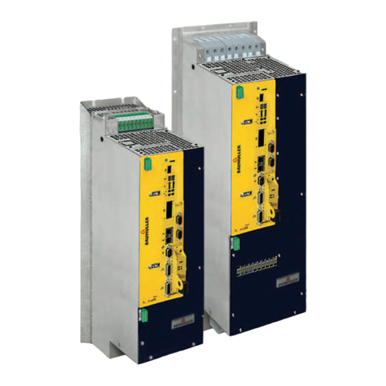
ESIGN AND PERATION The devices b maXX BM5500, BM5600, BM5700 consist of a power unit and a controller part within one housing. The devices differ in size, power, equipment (hard- and software) and cooling types, for further information refer to ZType code–... - Page 122 Design BM5700 BM5700 (continuous current units) are servo converters especially developed for main drives, derived from BM5500. The devices were developed to maximize the available rat- ed current by water cooling. For this reason these devices are only available with water cooling (cooling type -F and -Z) and with none peak current (only BM5773 with low peak current).
-
Page 123: Type Plate
Design and Operation Type plate On the type plate you will find, besides others, the type code of the device. BM5553-ST06-0100-0103-00-1234 Figure 58: Position of type plate NOTE! UL certification and a certified safety function within the meaning of PL classification according ISO 13849 or SIL according EN 61800 in preparation. -
Page 124: Type Code
Type code Type code The type code has the form: BM5XXX - XXXX[Ryy] - XXXX - XXXX - XX - XXXX. 4.3.1 Explanation type code BM5XXX-XXXX[Ryy]-XXXX-XXXX-XX-XXXX Device generation BM5XXX-XXXX[Ryy]-XXXX-XXXX-XX-XXXX Device design 0: Mains rectifier 1: Active mains rectifier 3: Axis unit safety 5: Basic unit/power module safety, universal units 6: Basic unit safety, acceleration units 7: Basic unit/power module safety, continuous current unit, water-cooled... - Page 125 Design and Operation BM5XXX-XXXX[Ryy]-XXXX-XXXX-XX-XXXX SAF-Module 0: no SAF module BM5-O-SAF A: -000-000-001 SAF module standard without parameter memory B: -000-000-000 SAF module with parameter memory STO controllable via I/O, with parameter memory, C: -001-000-000 without automatic restart STO controllable via I/O, with parameter memory, D: -001-000-002 with automatic restart STO controllable via I/O and FSoE, with parameter ...
- Page 126 Type code BM5XXX-XXXX[Ryy]-XXXX-XXXX-XX-XXXX Encoder reading 00: None 01: Encoder 1 and Encoder 2: ® ® HIPERFACE , EnDat 2.1, SSI, square and sine incremental encoder, resolver ® 02: Encoder 1 and Encoder 2: EnDat ® 03: Encoder 1 and Encoder 2: HIPERFCACE DSL ®...
- Page 127 Design and Operation The software option SoftDrivePLC is shown in the type code as follows: BM5XXX - XXXX - XXXX - XXXX - XX - XXXX-EXX, and XX > 01 NOTE! Only devices with type code BM5XXX-XXXX-XX01/03 and -XX04/05/06 provide an add-on module! The add-on modules are built-in and cannot be changed....
-
Page 128: Display And Operation Elements
Display and operation elements Display and operation elements Service interface 7 segment display Display controller state Meaning refer to: Z7-segment display controller– on page 129 LED H11 - H14 LED Meaning: refer to ZLED display controller– on page 130. ... -
Page 129: 7-Segment Display Controller
Design and Operation 4.4.1 7-segment display controller Refer to parameter manual for detailed description of drive states and state transitions. 0: Low, 1: High State Display Meaning drive manager NOT READY TO SWITCH ON Drive message „Not ready for switching power on“ SWITCH-ON INHIBIT Inhibit voltage, e.g. -
Page 130: Led Display Controller
Display and operation elements 4.4.2 LED display controller Naming on the Internal identification Meaning front plate 1.1 green, Axis 1: Torque direction 1.1 red H11 green: positive torque direction H11 red: negative torque direction 1.2 green, Axis 1: Power on (24 V available) / pulse enable 1.2 orange H12 green: power ON and pulse enable H12 orange: power ON only... -
Page 131: Led Display Fieldbus
Design and Operation 4.4.3 LED display fieldbus ® LED EtherCAT Type code BM5XXX-XXXX-XXXX-01XX BM5XXX-XXXX-XXXX-07XX Naming on the Meaning Blinking pattern front plate H31 (green) X3 Link / Act Off: No connection Connection Blinking: Data transfer H32 (yellow) ERROR ERROR (receiver error Phy1/Phy2) H41 (green) X4 Link / Act Off:... - Page 132 Display and operation elements Type code ® POWERLINK BM5XXX-XXXX-XXXX-04XX Naming on the Meaning Blinking pattern front plate H31 (green) X3 Link / Act Off: No connection Connection Blinking: Data transfer H32 (yellow) ERROR Off: NMT_CT3, NMT_CT7, NMT_GT2 NMT_CT11, NMT_GT6 Blinking: Configuration error (e.g.
-
Page 133: Setting The Ip Address With Address Switches
Design and Operation 4.4.4 Setting the IP address with address switches ® EtherCAT CoE BM5XXX-XXXX-XXXX-01XX ® EtherCAT BM5XXX-XXXX-XXXX-07XX VARAN BM5XXX-XXXX-XXXX-02XX ® POWERLINK BM5XXX-XXXX-XXXX-04XX IP-Address The IP address of the controller consists of 32 bits or 4 bytes (e.g. 192.168.125.203). S1 to S4 ®... - Page 134 Display and operation elements Instruction handbook b maXX BM5500, BM5600, BM5700 Document No.: 5.13008.10 Baumüller Nürnberg GmbH of 314...
- Page 135 Design and Operation ® ® Figure 60: Address switch setting EtherCAT , POWERLINK , VARAN Instruction handbook b maXX BM5500, BM5600, BM5700 Document No.: 5.13008.10 of 314...
- Page 136 Display and operation elements ® CANopen BM5XXX-XXXX-XXXX-03XX NOTE! Switch up = 0001 Baud rate S2 20 kBit/s 125 kBit/s, default setting switch 250 kBit/s 500 kBit/s 1 MBit/s Instruction handbook b maXX BM5500, BM5600, BM5700 Document No.: 5.13008.10 Baumüller Nürnberg GmbH of 314...
- Page 137 Design and Operation Address S3/S4 ® Figure 61: Address setting CANopen Instruction handbook b maXX BM5500, BM5600, BM5700 Document No.: 5.13008.10 of 314...
- Page 138 Display and operation elements Instruction handbook b maXX BM5500, BM5600, BM5700 Document No.: 5.13008.10 Baumüller Nürnberg GmbH of 314...
-
Page 139: Transport And Packaging
RANSPORT AND ACKAGING Safety notes for transport NOTICE! Damage due to unauthorized transport! Transport handled by untrained personnel can lead to a substantial amount of mate- rial damage. Therefore: m The unloading of the packages upon delivery as well as the in-house transport should only be done by trained personnel. -
Page 140: Transport Inspection
Transport inspection Transport inspection Upon receiving the delivered goods, immediately examine them for completeness and transport damage. If there is outwardly visible transport damage, proceed as follows: m Do not accept the delivery or conditionally accept it with reservations. m Note the extent of the damage on the transport documents or on the delivery note of the transport agent. -
Page 141: Mounting
OUNTING The device is designed for mounting in a control cabinet. Mounting consists of the following steps: 1 Prepare mounting (for drill holes/cut-out segments, refer to ZDrilling patterns– from page 145) 2 Install (fixing refer to ZMounting instructions– on page 151) Safety notes NOTE! Mounting shall only be performed by employees of the manufacturer or by other ... - Page 142 Safety notes WARNING! Danger as a result of incorrect mounting! The mounting requires qualified personnel with adequate experience. Incorrect mounting can lead to life-threatening situations or substantial material damage. Therefore: m Only allow mounting to be performed by employees of the manufacturer or by oth- er qualified personnel.
- Page 143 Mounting CAUTION! Danger due to sharp edges. If the device is lifted with unprotected hands during mounting, palms or fingers can be cut. If the device falls, feet could be injured. Therefore: m Ensure that only qualified personnel, who are familiar with the safety notes and as- sembly instructions, mount this device.
-
Page 144: Preparing For Mounting
Preparing for mounting Preparing for mounting Based on the planning documents and the drilling pattern (refer to ZDrilling patterns– from page 145), the cutout sections and the positions of the attachment drill holes can be determined. NOTICE! Property damage due to conductive contamination. Therefore: m When performing installation work of any kind, it must be ensured that no foreign material (e.g. -
Page 145: Drilling Patterns
Mounting 6.2.1 Drilling patterns Use the drilling pattern to make the necessary drill holes/cutout sections. NOTE! Consider the minimum clearances for cooling when making the drill holes. All dimensions in millimeters [mm]. Further notes refer to ZDimensions– from page 29 and ZCooling–... -
Page 146: Drilling Patterns Bm552X
Preparing for mounting 6.2.1.2 Drilling patterns BM552X BM552X-A BM552X-F BM552X-S BM552X-Z Figure 63: Drilling pattern BM552X 6.2.1.3 Drilling patterns BM553X BM553X-F BM553X-A BM553X-C BM553X-S BM553X-Z Figure 64: Drilling pattern BM553X, BM563X Instruction handbook b maXX BM5500, BM5600, BM5700 Document No.: 5.13008.10 Baumüller Nürnberg GmbH of 314... -
Page 147: Drilling Patterns Bm5X4X
Mounting 6.2.1.4 Drilling patterns BM5X4X BM5X4X-A BM5X4X-F BM5X4X-S BM5X4X-Z Figure 65: Drilling pattern BM554X, BM564X 6.2.1.5 Drilling patterns BM5X5X BM5X5X-A BM5X5X-S BM5X5X-F BM5X5X-Z Figure 66: Drilling pattern BM555X, BM565X Instruction handbook b maXX BM5500, BM5600, BM5700 Document No.: 5.13008.10 of 314... -
Page 148: Drilling Patterns Bm5X6X
Preparing for mounting Hole Figure 67: Drilling pattern BM565X-FXX9, BM575X-FXX9 6.2.1.6 Drilling patterns BM5X6X BM5X6X-S BM5X6X-A BM5X6X-Z BM5X6X-F Figure 68: Drilling pattern BM556X, BM565X Instruction handbook b maXX BM5500, BM5600, BM5700 Document No.: 5.13008.10 Baumüller Nürnberg GmbH of 314... -
Page 149: Drilling Patterns Bm5X7X
Mounting Figure 69: Drilling pattern BM566X-FXX9, BM5766-FXX9 6.2.1.7 Drilling patterns BM5X7X Figure 70: Drilling pattern BM557X-F, BM577X-F Instruction handbook b maXX BM5500, BM5600, BM5700 Document No.: 5.13008.10 of 314... - Page 150 Preparing for mounting Figure 71: Drilling pattern BM557X-A Instruction handbook b maXX BM5500, BM5600, BM5700 Document No.: 5.13008.10 Baumüller Nürnberg GmbH of 314...
-
Page 151: Mounting Instructions
Mounting Mounting instructions There are different kinds of mounting. Each mounting method is shown in a graphic (refer to ZFigure 72– on page 152 to ZFig- ure 75– on page 155). The screws and washers required for mounting are listed beneath the respective graphic. Carry out mounting as follows: 1 Provide suitable transport/lifting equipment as needed. - Page 152 Mounting instructions Figure 72: Mounting instruction BM554X-S/Z Device BM552X-S BM553X-S/Z BM554X-S/Z BM563X-Z BM564X-Z A - Screws 4 x M5 4 x M5 4 x M5 B - Washers 4 x (5.3 x 10) 4 x (5.3 x 10) 4 x (5.3x15) c - Mounting space c = 5 mm c = 5 mm...
- Page 153 Mounting Figure 73: Mounting instruction BM555X-S/Z, BM556X-S/Z Device BM555X-S/Z BM556X-S/Z BM565X-Z BM566X-Z A - Screws 4x M8 4x M8 B - Washers 4x (8.4x21) 4x (8.4x21) C - Mounting space c=7 mm c=7 mm Instruction handbook b maXX BM5500, BM5600, BM5700 Document No.: 5.13008.10 of 314...
- Page 154 Mounting instructions Figure 74: Mounting instruction BM557X-A/F, BM577X-FXX9 Device BM557X-A BM557X-F, BM577X-FXX9 A - Screws 38 x M6 22 x M6 B - Spring washer 38 x DIN6796-6-FST 22 x DIN6796-6-FST C - Washers 38 x (6.4 x 12.5) 22 x (6.4 x 12.5) Instruction handbook b maXX BM5500, BM5600, BM5700 Document No.: 5.13008.10 Baumüller Nürnberg GmbH...
- Page 155 Mounting Figure 75: Mounting instruction „diverse“ Device BM552X-A/F/Z/C BM553X-A/F/C BM554X-A/F BM555X-A/F BM556X-A/F BM563X-F BM564X-F BM565X-F BM566X-F A - Screws 4 x M5 14 x M4 16 x M5 16 x M8 20 x M8 B - Washers 4 x (5.3 x 10) 14 x (4.3 x 9) 16 x (5.3 x 15) 16 x (8.4x21) 20 x (8.4x21)
- Page 156 Mounting instructions WARNING! Danger because of conductive fluid in connection with electricity! The mounting drills are outside of the gasket. With non-waterproof fastening holes, e. g. the liquid coolant can ingress into the control cabinet. m Seal the mountings against water. Use, e.g., waterproof draw-in bolts and sealants between screws and bolts.
- Page 157 Mounting Figure 76: Control cabinet mounting BM552X-A/F Instruction handbook b maXX BM5500, BM5600, BM5700 Document No.: 5.13008.10 of 314...
-
Page 158: Requirements Mounting Plate For Cold Plate
Mounting instructions 6.3.1 Requirements mounting plate for cold plate The cooling version cold plate is a particular efficient cooling alternative. The heat dissi- pation is done via 2 contact surfaces. The first one is the mounting platform within the con- trol cabinet or on the machine base, the other is the cold plate on the device’s back. -
Page 159: Instruction Handbook B Maxx Bm5500, Bm5600, Bm5700
NSTALLATION This chapter describes the electrical installation of the device. The mechanical mounting is described in ZMounting– from page 141. Initial commissioning is described in the Parameter manual b maXX 5000 in chapter Commissioning. Prior to installation, ensure that the technical prerequisites have been fulfilled: 1 Check the demands on the electrical power supply. - Page 160 Safety notes WARNING! Danger because of incorrect installation and initial commissioning! Installation and commissioning require qualified personnel with adequate experi- ence. A installation fault can cause danger situations or large damage of property. Therefore: m Only personnel from manufacturer or qualified personnel operate while installation and initial commissioning DANGER! Risk of fatal injury from electrical current!
-
Page 161: Voltage Test
Installation Voltage test DANGER! Risk of fatal injury from electrical current! During the routine test of these devices, a voltage test is performed by Baumüller Nürnberg GmbH in accordance with EN 61800-5-1, Section 5.2.3.2. It is thus unnec- essary for the customer to do this. Therefore: m Subsequent tests of the devices using high voltages may only be performed by Baumüller Nürnberg GmbH. - Page 162 Demands on the power supply m Connection instructions at special power supply systems Note: Not valid for b maXX power modules. n Single phase connection (BM551X) BM551X Abbildung 77: Single phase connection BM551X n Connection to single phase grounded power supply systems (BM552X ..
-
Page 163: Requirements To The Connecting Cables
Installation n Connection to single phase grounded power supply systems with isolated trans- former for the following cases 1) BM552X except for IT power supply systems 2) BM553X ... BM557X, BM56XX, BM57XX at operating altitude > 2000 m Figure 79: Connection to single phase grounded power supply systems with an isolated transformer Requirements to the connecting cables h Take into account IEC/EN 60204-1, Chapter 13 when selecting the cable. -
Page 164: Pe Connection And Rcd Compatibility
PE connection and RCD compatibility PE connection and RCD compatibility Depending on the functional principle, leakage current >3.5 mA or >10 mA can flow through the protective ground conductor. Consequently, a stationary ground conductor connection in accordance with EN 61800-5-1 is required. DANGER! Risk of fatal injury from electrical current! This product can cause direct and/or alternating current in the protective ground con-... -
Page 165: Avoid Bearing Currents
Installation In order to have EMC-compliant and problem-free use within the framework of the legis- lation, the following aspects must be taken into account. In case of any questions, please contact Sales or the Applications department of Baumüller Nürnberg GmbH. m Only use Baumüller motor cables and Baumüller components. - Page 166 Avoid bearing currents NOTE The reduction of bearing currents requires the consideration of the whole speed- variable drive system and its installation! Baumüller supports you with on-site measurements and with development and imple- mentation of suitable preventative measures. Avoiding bearing m Basically the grounding system must be installed appropriately to ensure a forced re- damage turn of the common mode current.
-
Page 167: Requirements For The Motor Temperature Sensors
Installation Installation of toroidal cores h The three phases without shielding and without PE must be lead through the cores. The cores must be installed and attached near the motor connection of the BM5500, BM5600, BM5700 . h When using toroidal cores it is further recommended to use current isolated bearings on the nondrive end for synchronous/asynchronous main drives sizes 180 and higher. -
Page 168: Installation Procedure
7.10 Installation procedure 7.10 Installation procedure DANGER! Risk of fatal injury from electrical current! Electrically live parts are life-threatening. Therefore: m Make certain that the parts to be mounted (e.g. power supply cables) and the mounting areas are de-energized for the entire duration of mounting the device. NOTE! Steps which are not necessary for the installation of b maXX power modules are marked. - Page 169 Installation Connect the device via the power supply terminals 1U1, 1V1 and 1W1 to the power choke output - not necessary for power modules. Connect the protective conductor to the terminal PE (a fixed ground conductor con- nection is mandatorily specified). Connect 24 V power supply:...
-
Page 170: Wiring Diagrams
7.11 Wiring diagrams 7.11 Wiring diagrams The connection diagrams are separated in connection diagrams for the electrical mains, motor etc., ZPage 183– and the controller connections ZPage 193–. NOTE! The identifiers 1C1 and 1D1 were taken over from DIN EN 60445. 1C1 is the connec- tion to the positive DC link cable/rail, and in the past was identified by Baumüller in some devices as ZK+. -
Page 171: Connection Diagrams Without Controller Connections
Installation 7.11.1 Connection diagrams without controller connections 7.11.1.1 BM55XX, BM56XX, BM57XX (basic units) To connected devices BM3000/BM5000 X300 Signal bus Figure 82: Connection diagram with a directly controlled motor brake - basic units Instruction handbook b maXX BM5500, BM5600, BM5700 Document No.: 5.13008.10 of 314... - Page 172 7.11 Wiring diagrams HINWEIS! If the motor brake is connected directly via X101-2 and X101-3 (refer to ZFigure 82– on page 171), the shown direct installation is allowed only. It is not allowed within a multi-axis installation e.g. to connect the plus and ground connections of all motor brakes with each other.
- Page 173 Installation To connected devices BM3000/BM5000 X300 Signal bus Figure 83: Connection diagram with motor brake controlled via an add. relay - basic units Instruction handbook b maXX BM5500, BM5600, BM5700 Document No.: 5.13008.10 of 314...
-
Page 174: Bm55Xx, Bm56Xx, Bm57Xx Power Module
7.11 Wiring diagrams 7.11.1.2 BM55XX, BM56XX, BM57XX power module To connected devices BM3000/BM5000 X300 Signal bus Figure 84: Connection diagram with a directly controlled motor brake - power modules Instruction handbook b maXX BM5500, BM5600, BM5700 Document No.: 5.13008.10 Baumüller Nürnberg GmbH of 314... - Page 175 Installation NOTE If the motor brake is connected directly via X101-2 and X101-3 (refer to ZFigure 82– on page 171) the shown direct installation is allowed only. It is not allowed within a multi-axis installation e.g. to connect the plus and ground connections of all motor brakes with each other.
- Page 176 7.11 Wiring diagrams To connected devices BM3000/BM5000 X300 Signal bus Figure 85: Connection diagram with motor brake controlled via an additional relay - power modules Instruction handbook b maXX BM5500, BM5600, BM5700 Document No.: 5.13008.10 Baumüller Nürnberg GmbH of 314...
-
Page 177: Connection Of Several Devices To The Dc Link Without Using The Signal Bus
Installation 7.11.1.3 Connection of several devices to the DC link without using the signal bus There are the following possibilities to connect devices. Via X300 Do not connect power supply bus X100:3 and brake resistor bus X100:4! signal bus Signal bus X300 Figure 86: Connection of several devices BM5500 via signal bus... - Page 178 7.11 Wiring diagrams Is only valid for BM554X, BM555X, BM556X, accordingly the cooling versions S and A, for BM557X cooling version -A: Figure 88: Connection fan BM557X-A The power supply at X100 or X101 must externally be protected. At selection of the fuse you must consider the cross-section of the connecting cable and the maximum allowable load capacity (for X100: refer to X100 on ZPage...
-
Page 179: Terminal Overviews
Installation 7.11.2 Terminal overviews ZFigure 92– on page 183 and the following show the connections for protective conduc- tors, power supply, motor, brake resistor, DC-link and motor temperature sensor (X101). ZConnections controller– from page 193 shows the control voltage and the connections of the controller unit. -
Page 180: Terminals Bm551X
7.11 Wiring diagrams 7.11.2.1 Terminals BM551X *) Do not apply terminals when using a power module! Figure 89: Electrical connections for power supply, motor, ... for BM551X Instruction handbook b maXX BM5500, BM5600, BM5700 Document No.: 5.13008.10 Baumüller Nürnberg GmbH of 314... -
Page 181: Terminals Bm552X
Installation 7.11.2.2 Terminals BM552X *) Do not apply terminals when using a power module! Figure 90: Electrical connections for power supply, motor, ... for BM552X Instruction handbook b maXX BM5500, BM5600, BM5700 Document No.: 5.13008.10 of 314... -
Page 182: Terminals Bm553X, Bm563X
7.11 Wiring diagrams 7.11.2.3 Terminals BM553X, BM563X *) Do not apply terminals when using a power module! Figure 91: Electrical connections for power supply, motor, ... for BM5X3X Instruction handbook b maXX BM5500, BM5600, BM5700 Document No.: 5.13008.10 Baumüller Nürnberg GmbH of 314... -
Page 183: Terminals Bm554X, Bm564X
Installation 7.11.2.4 Terminals BM554X, BM564X *) Do not apply terminals when using a power module! **) only BM554X-S/-A Figure 92: Electrical connections for power supply, motor, ... for BM5X4X Instruction handbook b maXX BM5500, BM5600, BM5700 Document No.: 5.13008.10 of 314... -
Page 184: Terminals Bm555X, Bm556X, Bm565X, Bm566X
7.11 Wiring diagrams 7.11.2.5 Terminals BM555X, BM556X, BM565X, BM566X *) Do not apply terminals when using a power module! **) Only BM555X-S/-A and BM556X-S/-A Figure 93: Electrical connections for power supply, motor, ... for BM5X5X, BM5X6X NOTE! The brake resistor is connected at BM5X5X and BM5X6X between Ba- and 1C1. Also refer to ZFigure 82–... -
Page 185: Terminals Bm566X, Bm576X
Installation 7.11.2.6 Terminals BM566X, BM576X Figure 94: Electrical connections for power supply, motor, ... for BM5X6X Instruction handbook b maXX BM5500, BM5600, BM5700 Document No.: 5.13008.10 of 314... -
Page 186: Terminals Bm5755
7.11 Wiring diagrams 7.11.2.7 Terminals BM5755 Figure 95: Electrical connections for power supply, motor, .. for BM5755 Instruction handbook b maXX BM5500, BM5600, BM5700 Document No.: 5.13008.10 Baumüller Nürnberg GmbH of 314... -
Page 187: Terminals Bm557X, Bm5773
Installation 7.11.2.8 Terminals BM557X, BM5773 *) Only BM557X-A Figure 96: Electrical connections for power supply, motor, .. for BM557X and BM5773 Instruction handbook b maXX BM5500, BM5600, BM5700 Document No.: 5.13008.10 of 314... - Page 188 7.11 Wiring diagrams NOTE! The brake resistor is connected at the devices BM557X, BM577X between Ba- and 1C1. Also refer to ZFigure 82– on page 171. DANGER! Risk of fatal injury from electrical current! Therefore: After attaching all power cables to the device BM557X and BM577X, screw on the cover careful to all screwing points by using the enclosed screws (6xM4x12) and washers.
-
Page 189: Electrical Connection Power Unit
Installation 7.11.3 Electrical connection power unit Power system Max. cross-section Connection Torque Load capacity 1U1, 1V1, 1W1, PE of connection technology BM551X 2.5 mm Terminal block Refer to ZFuses– from BM552X 4.0 mm Screw terminal Min. 0.5 Nm page 266 Max. - Page 190 7.11 Wiring diagrams DC link Max. cross-section Connection tech- Torque Load capacity 1C1 and 1D1 of connection nology 1C1 and 1D1 Ballast Ba+ and Ba- Ba+ and Ba- BM551X 2.5 mm Terminal block Refer to ZElectrical data BM552X 4.0 mm Screw terminal Min.
- Page 191 Installation Motor Max. cross-section Connection tech- Torque Load capacity 1U2, 1V2, 1W2, PE of connection nology BM551X 2.5 mm Terminal block Is limited by the device, BM552X 4.0 mm Screw terminal Min. 0.5 Nm also refer to Max. 0.6 Nm ZTechnical BM553X 16 mm...
-
Page 192: Requirements For The Screwing
7.11 Wiring diagrams X100 (SELV/PELV) Max. cross-section Connection Load capacity of connection technology 24 V power supply 1.5 mm Terminal block X100-1, X100-2, X100-5 and X100- 6: max. 8.0 A, if you consider UL508C: max. 4.0 A NOTICE! It is forbidden to connect both the signal bus X300 and the power supply bus/brake resistor bus X100:3/X100:4. -
Page 193: Controller Terminals
Installation 7.12 Controller terminals Type code: BM5XXX-XXXX-XX01 bzw. XX06 X1: Service interface NOTE! Only the service cable BM5-K-USB-XXX is allowed to be used for the service interface X1, refer to ZService interface cable– page 293 X2 Digital inputs/outputs 1 11 1:Refer to ZPage 195–... - Page 194 7.12 Controller terminals Type code: From BM5XXX-XXXX-XXXX-XX08 X1: Service interface NOTE! Use service cable BM5-K-USB-XXX, refer to ZService interface cable– on page 293 X2 Digital inputs/outputs 1 11 1:+24V (SELV/PELV) 2 to 3: BB On (SELV/PELV) 4 to 7: Digital output (SELV/PELV) 8: M24V (SELV/PELV) 9 to 10: N.C.
- Page 195 Installation X2 Digital inputs/outputs Assessment Signal edge, programmable Input current per input 2 mA digital input, 20 mA fast digital input Input propagation delay Max. 4 ms Max. 10 µs for fast inputs Level Low (0 .. 5 V) High (12 … 28 V) Output current per output 500 mA Galvanic separation...
- Page 196 7.12 Controller terminals X3 / X4 - fieldbus connection ® ® EtherCAT Type code BM5500, BM5600, BM5700 with EtherCAT CoE profile: BM5XXX-XXXX-XXXX-01XX ® Type code BM5500, BM5600, BM5700 with EtherCAT SoE profile: BM5XXX-XXXX-XXXX-07XX ® X3 EtherCAT IN ® EtherCAT Number of bus connections 1 IN / 1 OUT Bus connection RJ 45...
- Page 197 Installation VARAN Type code BM5500, BM5600, BM5700 with VARAN profile: BM5XXX-XXXX-XXXX-02XX X3 VARAN IN VARAN OUT Number of bus connections 1 IN / 1 OUT Bus connection RJ 45 Number of parameters Refer to parameter handbook BM5000 Data width of parameters 16 / 32 Bit Baud rates 10 / 100 Mbit/s...
- Page 198 7.12 Controller terminals ® ® CANopen Type code BM5500, BM5600, BM5700 with CANopen BM5XXX-XXXX-XXXX-03XX ® X3 CANopen IN ® CANopen 4 kByte DP-RAM, 256 kByte RAM, Memory 1 MByte Flash-Eprom Number of bus connections 2, no slot rules Bus connection 2 connectors RJ45, 8-pole Baud rates 20/125/250/500/1000 kBit/s...
- Page 199 Installation ® ® POWERLINK Type code BM5500, BM5600, BM5700 with POWERLINK BM5XXX-XXXX-XXXX-04XX ® X3 POWERLINK IN ® POWERLINK Number of bus connections 1 IN / 1 OUT Bus connection RJ 45 Number of parameters Refer to parameter handbook BM5000 Data width of parameters 16 / 32 Bit Baud rates 10 / 100 Mbit/s...
- Page 200 7.12 Controller terminals Add-on module IEE with external supply Incremental encoder emulation, 2 channels, BM5XXX-XXXX-XX01 Set values for incremental encoder emulation can be evaluated from following sources: m Position actual values encoder 1 or encoder 2 m Position set values (e. g. internal from positioning) m Fieldbus set value (external set via bus) The generated signal can be used either for synchronization of the following axis or for position evaluation of the axis by the master control.
- Page 201 Installation Add-on module SIE SSI encoder emulation, 2 channels, BM5XXX-XXXX-XX03 Set values for SSI encoder emulation can be evaluated from following sources: m Position actual values encoder 1 or encoder 2 m Position set values (e. g. internal from positioning) m Fieldbus set value (external set via bus) The generated signal can be used either for synchronization of the following axis or for position evaluation of the axis by the master control.
- Page 202 7.12 Controller terminals Add-on module SVP Module with additional analog/digital inputs/outputs, BM5XXX-XXXX-XX04 BM5XXX-XXXX-XX05 BM5XXX-XXXX-XX06 LED display green: 24V available orange: Internal power supply available green: FPGA loaded Figure 99: LED display add-on module SVP Digital inputs/outputs Evaluation: Edges, programmable Input current (per input): 2 mA digital input Time delay input: Max.
- Page 203 Installation Analog inputs Voltage input Current input Resolution 14 bit Type Differential input ca. 100 Input resistance ca. 50 k Input current Max. 250 µA Min. (0) 4 A, max. 20 mA Input voltage -10 V to +10 V Max.
- Page 204 7.12 Controller terminals Pin assignment front side connectors: 2 x 24V in 2 x GND in Digital out 1 Digital in 1 Digital out 2 Digital in 2 Digital out 3 Digital in 3 Digital out 4 Digital in 4 24V out Analog in 1 + GND out...
- Page 205 Installation Connection m Analog input/output 2 4 V 2 4 V V e r s o r g u n g 2 4 V Power supply a n a l o g u n d G N D analog and G N D d i g i t a l G N D...
- Page 206 7.12 Controller terminals X6 Analog inputs/outputs 1: Input 1 + 2: Input 2 + 3: GND 4: Output 1 + 5: Output 2 + 6: Input 1 - 7: Input 2 - 8: Output 1 (GND) 9: Output 2 (GND) Only one encoder can be connected to each encoder connection.
- Page 207 Installation X6 Analog inputs/ There are two analog inputs and outputs available. outputs Inputs Resolution 12 bit Type Differential input Input resistance Approx. 50 k Max. input current 200 µA Sampling rate 5 µs Input voltage +10 V to -10 V Outputs Resolution 12 bit...
- Page 208 7.12 Controller terminals X7 / X8 Encoder evaluation, refer to ZFigure 102– on page 206 Connector assignment depends on encoder selection Resolver encoder All encoders, that comply with the following technical specification, may also be used: evaluation Pole pair number The ratio between the pole pair number of the motor and the pole pair number of the encoder must be inte- ger.
- Page 209 Installation ® Sine cosine en- The Sine cosine encoder evaluation is provided with a Hiperface -interface. coder evaluation The encoders, which meet the following technical specifications, can be used: ® Hiperface Voltage supply 10 V ® Signal level Hiperface - specification of the process data channel (~1 V ;...
- Page 210 7.12 Controller terminals Encoder evalua- The encoders, which meet the following technical specifications, can be used: tion with ® EnDat 2.1 or SSI Voltage supply controlled Signal level ~1 V Current input Max. 250 mA GND encoder supply +5 V encoder supply Clock + A + (COS +) A - (COS -)
- Page 211 Installation Encoder evalua- The encoders, which meet the following technical specifications, can be used: tion with ® EnDat Voltage supply controlled Signal level ~1 V Current input Max. 250 mA GND encoder supply +5 V encoder supply Clock+ Reserved * Reserved * Reserved * Reserved *...
- Page 212 7.12 Controller terminals Sine or square The encoders, which meet the following technical specifications, can be used: wave encoder evalua- Voltage supply controlled tion Signal level RS422 (TTL) for square wave incremental encoders ~1 Vss for sine incremental encoders Current input Max.
- Page 213 Installation Encoder evalua- The encoders, which meet the following technical specifications, can be used: tion with ® Hiperface DSL ® Signal level Hiperface DSL Current input Max. 250 mA GND encoder supply 10 V encoder supply Reserved * Reserved * Reserved * Reserved * Reserved *...
- Page 214 7.12 Controller terminals Sine incremental Encoders with high-resolution incremental signals (sine and cosine signals, e.g. 2048 sig- encoder with com- nal periods per revolution) and in addition commutation signals (sine and cosine track mutation signals with 1 signal period per revolution), available firmware 1.15 and higher. Voltage supply controlled Signal level...
- Page 215 Installation X300 signal bus If a system is constructed of BM50XX, BM51XX, BM5300 and BM55XX, then all devices are linked with each other via the signal bus. This bus can poll every client device, including the mains rectifier unit, and send individual signals. Via this bus, the mains rectifier unit can register errors to the axes so that the individual axes can react to these.
- Page 216 7.12 Controller terminals Instruction handbook b maXX BM5500, BM5600, BM5700 Document No.: 5.13008.10 Baumüller Nürnberg GmbH of 314...
-
Page 217: Operation
PERATION Basic information WARNING! Risk of injury due to improper operation! Improper operation can lead to severe personal injury or material damage. Therefore: m Perform all operational steps according to the details of these instruction hand- book. m Before beginning any work, ensure that all coverings and protective devices are installed and are functioning properly. -
Page 218: Operating Concept
Operating concept WARNING! Risk of injury due to insufficient qualifications! Inevitably, when operating this electrical device, certain parts of this device are ener- gized with hazardous voltage. Improper handling can lead to significant personal in- jury and material damage. Therefore: m Only qualified personnel may work on this device! Operating concept After the device has been commissioned it is parameterized (i. -
Page 219: Power On Switching Frequency / Dc Link Charging
Operation Power on switching frequency / DC link charging 8.2.1 Power supply switch-on frequency BM551X and BM552X The devices use a rectifier with 6 diodes (B6U circuit). There is a resistor between rectifier and DC link capacitor limiting the charging surge. The resistor is bridged by a relay after the charging. -
Page 220: Calculation Of The Maximum Permitted External Capacitance
Power on switching frequency / DC link charging 8.2.3 Calculation of the maximum permitted external capacitance If a maximum allowable external capacitance is specified in the technical characteristics, then it is either a device with diode rectification or one with the „old“ charge circuit (time controlled charging). -
Page 221: Effects Of The Different Charging Circuits
Operation 8.2.4 Effects of the different charging circuits Following incompatibilities result because of charging and must be checked by the user operating devices with the new current-controlled charging-method. m Charging time: Adapt timeout values in master-control to avoid possible error messag- es because of not in time ready-to-operate signal. -
Page 222: Monitoring
Monitoring Monitoring The controller unit monitors the device during operation. If the controller unit detects a state that deviates from the normal operation condition, the device either transmits a warning or an error message. Warning If the controller unit detects an operating condition that exceeds a warning threshold, a corresponding warning is shown on the display or, respectively, controller. -
Page 223: Fieldbus Communication
Operation Fieldbus communication Depending on the version of BM5500, BM5600, BM5700 (refer to ZType code– from page 124), communication can be made via different fieldbus systems. ® 8.4.1 EtherCAT ® Type code BM5500, BM5600, BM5700 with EtherCAT ® ® BM5XXX-XXXX-XXXX-01XX- CoE profile (CANopen over EtherCAT ®... - Page 224 Fieldbus communication ® Parameters The parameter settings determine the behavior of the EtherCAT -Slave in operation. Pa- rameters are set with the software ProDrive. 1 Start ProDrive 2 Click on „Project Tree“. 3 Communication settings with ProDrive n Project Tree: Configuration/Fieldbus Slave (refer also Parameter manual b maXX 5000) m Set Synchronization to „On“...
-
Page 225: Varan
Operation 8.4.2 VARAN. Type code BM5500, BM5600, BM5700 with VARAN: BM5XXX-XXXX-XXXX-02XX- A BM5500, BM5600, BM5700 with fieldbus option VARAN can communicate with a VA- RAN master. ® X3 and X4 on the front side of the device are the RJ45 connections for EtherCAT -line (also refer to ZController terminals–... - Page 226 Fieldbus communication n Please, observe an EMC-compatible laying of the Ethernet connection cables! n The following cables were released for use by Baumüller: Ethernet connection cable; ® Further information refer ZAccessories Ethernet/EtherCAT /VARAN/ ® POWERLINK .– on page 292. Commissioning.
-
Page 227: Canopen
Operation ® 8.4.3 CANopen ® Type code BM5500, BM5600, BM5700 with CANopen BM5XXX-XXXX-XXXX-03XX- ® The data can be transmitted to all the other CAN-users (e g from CANopen master) via the BM5500, BM5600, BM5700 . X3 and X4 are the RJ45 connections for CAN bus cables (also refer to ZController termi- nals–... - Page 228 Fieldbus communication Process of The test-commissioning is divided into the following sections: commissioning ® 1 Configuration of the CANopen slave ® 2 Testing of the CANopen slave ® Configuring the CANopen slave ® The CANopen is configured at the running device with ProDrive and a NMT-Master. ®...
-
Page 229: Powerlink
Operation ® 8.4.4 POWERLINK ® Type code b maXX BM5500, BM5600, BM5700 with POWERLINK BM5XXX-XXXX-XXXX-04XX- ® b maXX BM5500, BM5600, BM5700 devices can communicate with a POWERLINK ® Managing Node via the fieldbus connection POWERLINK ® X3 and X4 on the front side of the device are the RJ45 connections for POWERLINK (also refer to ZController terminals–... - Page 230 Fieldbus communication Instruction handbook b maXX BM5500, BM5600, BM5700 Document No.: 5.13008.10 Baumüller Nürnberg GmbH of 314...
-
Page 231: Maintenance
AINTENANCE Safety notes Basic information DANGER! Risk of fatal injury from electrical current! Inevitably, when operating this electrical device, certain parts of it are energized with hazardous voltage. Therefore: m Pay heed to areas on the device that could be dangerous during the electrical in- stallation. -
Page 232: Environmental Condition
Environmental condition Environmental condition If the prescribed environmental conditions are adhered to, then the device is mainte- nance-free. For the prescribed environmental conditions, refer to ZRequired environmen- tal conditions– on page 53. The most important prescribed environmental conditions are: m Dust-free environmental air m Temperature: Min. - Page 233 Maintenance DANGER! Risk of fatal injury from electrical current! Stored electric charge. Discharge time of the system = discharge time of the device with the longest DC link discharge time in the DC link connection. Refer to ZElectrical data basic units– from page 61.
-
Page 234: Periodic Maintenance
Inspection intervals - maintenance notes 9.3.1 Periodic maintenance m Environmental condition Check points Methods and criteria Inspection intervals Daily Semi- Annu- annu- ally ally Check environmental temperature, humidity and Visual inspection and measurement of the environmen- vibrations. tal conditions, comparison with standard values. Check whether dust, oil or drops of water appear. - Page 235 Maintenance m Connections and circuitry of the mains power supply Check points Methods and criteria Inspection intervals Daily Semi- Annu- annu- ally ally Does the wiring indicate any color or shape Visual inspection changes due to overheating? Is the wiring insulation damaged or is it discol- Visual inspection ored? Is there any damage?
-
Page 236: Repairs
Repairs m Cooling system fans Check points Methods and criteria Inspection intervals Daily Semi- Annu- annu- ally ally Are there any abnormal noises or vibrations? Visual and audio check Are there any loose screws? Tighten the screws. m Cooling system ventilation duct Check points Methods and criteria Inspection intervals... -
Page 237: Troubleshooting And Fault Correction
ROUBLESHOOTING AND FAULT CORRECTION 10.1 Behavior in case of malfunctions Basic information DANGER! Risk of fatal injury from electrical current! Inevitably, when operating this electrical device, certain parts of it are energized with hazardous voltage. Therefore: m Pay heed to areas on the device that could be dangerous. WARNING! Risk of injury due to improper fault correction! Therefore:... -
Page 238: Monitoring Functions
10.2 Monitoring functions 10.2 Monitoring functions Monitoring function Warning/error Mains voltage Mains undervoltage Mains overvoltage Phase monitoring Phase failure Mains failure Ground fault Fault current to ground Overcurrent Motor overcurrent DC link DC link overvoltage DC link relative undervoltage Overload monitoring Peak current not possible at this time Heat sink temperature... - Page 239 Troubleshooting and fault correction Monitoring function Warning/error Encoder 2 Cable break Cable break (SIN² + COS²) Excessive rotational speed Cyclical specified value Time-out during transmission transmission to the fieldbus Blockage monitoring Drive blocked Signal bus Feed-in ready-to-operate Phase failure Brake resistance on Malfunction Signal bus warning X: Implemented...
- Page 240 10.2 Monitoring functions Power supply - Not available at power modules voltage This monitoring function checks if the power supply voltage has a value within the adjust- ed voltage range. Phase monitoring - not available at power modules This monitoring function checks the three phases of the power supply voltage. If one phase is missing, the warning "Phase failure"...
- Page 241 Troubleshooting and fault correction Motor This monitoring function checks the temperature of motor. If the I t-threshold is exceeded, temperature then the error message „I²t overload“ is generated by the controller. Only for If the set temperature threshold 1 is exceeded, then the warning „Temperature threshold KTY84 and PT1000...
- Page 242 10.2 Monitoring functions Signal bus - Supply not ready for use This signal indicates also the state of the supply. It is required if axes units will be oper- ated in a DC link network with several BM5500, BM5600 und BM5700 . In this case it can only be evaluated by the „Supply ready for use“...
-
Page 243: Fault Detection
Troubleshooting and fault correction 10.3 Fault detection The fault can be caused by mechanical or electrical malfunctions. The occurrence of an error state is signalized by the lighting up of the red LED H14 on the front side of the housing. The meaning of the individual LEDs is explained in ZLED display controller–... -
Page 244: Error Handling
10.4 Error handling 10.4 Error handling NOTE! The device is shipped with predefined error reactions. With regard to the error mes- sages identified with „depending on the setting“ in the „Reaction“ column, the device's error reaction can be adjusted. Errors that, due to safety reasons, have an immediate pulse inhibit as a consequence, may not be changed. -
Page 245: Accessories And Spare Parts
CCESSORIES AND PARE ARTS Accessories/spare parts for devices of the b maXX series are listed in this appendix. Product management is happy to handle any queries and suggestions on accessory parts. Instruction handbook b maXX BM5500, BM5600, BM5700 Document No.: 5.13008.10 of 314... -
Page 246: Cabling
11.1 Cabling 11.1 Cabling 11.1.1 Cables power supply-device Device Number of wires x Connection to device Maximum length cross section BM551X 4 x 0.5 bis 2.5 mm Flexible cable Power supply to mains filter: (AWG 16 - 12) with/without wire end ferrule user-defined (terminal block) mains filter to power choke/... - Page 247 Accessories and Spare Parts Connection lugs (current bars). Position refer to ZFigure 93– on page 184 . Screw maximum two cable lugs to the current bar - one on the front side, one on the reverse side of the bar. Connection lugs (current bars).
-
Page 248: Cables Device-Motor
11.1 Cabling 11.1.2 Cables device-motor 2)3) Device Number of wires x Maximum length Connection to device cross section BM551X 4 x 1 bis 2.5 mm 100 m Flexible cable with/without wire (AWG 16 - 12) end ferrule (terminal block) BM552X 4 x 2 bis 4 mm 1.5 bis 2.5 mm : 100 m... - Page 249 Accessories and Spare Parts Connection lugs (current bars). Position refer to ZFigure 93– on page 184 Screw maximum two cable lugs to the current bar - one on the front side, one on the reverse side of the bar. Connection lugs (current bars).
-
Page 250: Hybrid Cable Device-Encoder-Motor
11.1 Cabling 11.1.3 Hybrid cable device-encoder-motor Selection The trailing cables are suitable for mobile deployment, for example in mobile cable han- dlers. In addition, the cable sheath can be used in environments with acids and bases (e.g. coolant). ® The encoder wires for HIPERFACE DSL encoders are connected with the device. - Page 251 Accessories and Spare Parts ® m Motor cable with HIPERFACE DSL 15 A Connect the cable shielding via the strain relief clamp 400 mm of the connector housing. Data cable shielded Cable length (according order) DSL- blue DSL+ white GN/GE Connect cable shield with the housing of the connector.
- Page 252 11.1 Cabling ® m Motor cable with HIPERFACE DSL 20 A Connect the cable shielding 400 mm via the strain relief clamp Data cable shielded of the connector housing. Cable length DSL- blue (according order) DSL+ white GN/GE Connect cable shield with the housing of the connector.
- Page 253 Accessories and Spare Parts ® m Motor cable with HIPERFACE DSL 21 A Connect the cable shielding via the strain relief clamp 400 mm of the connector housing. Cable length Data cable shielded (according order) DSL- blue DSL+ white GN/GE Connect cable shield with the housing of the connector.
- Page 254 11.1 Cabling ® m Motor cable with HIPERFACE DSL 28 A Connect the cable shielding via the strain relief clamp 400 mm of the connector housing. Cable length Data cable shielded (according order) DSL- blue DSL+ white GN/GE Connect cable shield with the housing of the connector.
- Page 255 Accessories and Spare Parts ® m Motor cable with HIPERFACE DSL 36 A Connect the cable shielding via the strain relief clamp of the connector housing. 400 mm Cable length Data cable shielded (according order) DSL- blue DSL+ white GN/GE Connect cable shield with the housing of the connector.
-
Page 256: Control Voltage Supply/Signal Cable
11.1 Cabling 11.1.4 Control voltage supply/signal cable 1.5 mm Cross-section Maximum length (without digital I/O) Discretionary Maximum length with digital I/O 30 m Connection to device Without/with wire end ferrule (clamp terminal) The type of routing is discretionary. The length of the cable has no influence on adherence to the EMC law. 11.1.5 Encoder cables Selection of the The trailing cables are suitable for mobile deployment, for example in mobile cable han-... - Page 257 Accessories and Spare Parts Encoder with Encoder with Encoder with ® ® ® EnDat /SSI EnDat HIPERFACE DSL Part No. Part No. Refer to ZHybrid cable device-encoder-motor– ® ® Length speedtec speedtec on page 250 429986 448796 458805 465906 429987 448797 458806 465907...
-
Page 258: Connecting Cable For Resolver
11.1 Cabling 11.1.5.1 Connecting cable for resolver The connecting cable is available as accessory part from Baumüller Nürnberg GmbH. Follow the instructions below if a self-made cable is to be used: 1 Utilize the following materials: m Cable: Li9YC 1x2x0.25-Li9Y 2x2x0,25-Li9Y C11Y 1x2x0.34GN. m High-density D-sub connector: 26-pin, male m Round connector: 12-pin, female (e.g. -
Page 259: Connecting Cable For Encoders With Hiperface
Accessories and Spare Parts ® 11.1.5.2 Connecting cable for encoders with HIPERFACE The connecting cable is available as accessory part from Baumüller Nürnberg GmbH. Follow the instructions below if a self-made cable is to be used: 1 Utilize the following materials: m Cable: Li9YC3x2x0.25-Li9Y3x2x0,25-Li9Y C11Y 1x2x0.34GN. -
Page 260: Connecting Cable For Encoder With Endat ® Or Ssi
11.1 Cabling ® 11.1.5.3 Connecting cable for encoder with EnDat or SSI The connecting cable is available as accessory part from Baumüller Nürnberg GmbH. Follow the instructions below if a self-made cable is to be used: 1 Utilize the following materials: m Cable: Li9YC3x2x0.25-Li9Y3x2x0,25-Li9Y C11Y 1x2x0.34GN. -
Page 261: Connecting Cable For Encoder With Endat ® 2.2
Accessories and Spare Parts ® 11.1.5.4 Connecting cable for encoder with EnDat ® The connecting cable is available as accessory part with M12 or speedtec M23 from Baumüller Nürnberg GmbH. Follow the instructions below if a self-made cable with M12 is to be used: 1 Utilize the following materials: m Cable: 4 x 0,38 + 1 x (4 x 0,14) m High-density D-sub connector: 26-pin, male... - Page 262 11.1 Cabling ® ® speedtec Follow the instructions below if a self-made cable with speedtec M23 is to be used: 1 Utilize the following materials: m Cable: 4 x 0,38 + 1 x (4 x 0,14) m High-density D-sub connector: 26-pin, male ®...
-
Page 263: Connecting Cable For Sine/Square-Wave Incremental Encoder
Accessories and Spare Parts 11.1.5.5 Connecting cable for sine/square-wave incremental encoder The connecting cable is available as accessory part from Baumüller Nürnberg GmbH. Follow the instructions below if a self-made cable is to be used: 1 Utilize the following materials: m Cable: Li9YC3x2x0.25-Li9Y3x2x0,25-Li9Y C11Y 1x2x0.34GN. -
Page 264: Connection Cable Add-On Modules
ZConnecting cable for sine/square-wave incremental encoder– on page 263) with the other cable ending. Figure 116: Connection cable IEE with b maXX 5500 NOTE! The connection cable must be made according above mentioned instruction, pin as- on page 199! ... - Page 265 Accessories and Spare Parts The connection cable is not offered by Baumüller and must be made by the user: 1 Use the following materials: m Cable: LiYCY 2 x (2 x 0.14 mm²) + 1 x 0,34 mm² Cu braiding. m Sub-D connector: 9-pole, female (SIE side) m Cables must be of twisted pair wire (track DAT+/DAT-, CLK+/CLK-) from SSI encod- er emulation to further master control systems...
-
Page 266: Fuses
11.2 Fuses 11.2 Fuses NOTE! The fuse specification are valid for basic units, only. A distinction is made between protecting the power supply cables and protecting the de- vice. To fulfill CE specifications – here in particular EN 60204-1 – fuse the power supply cables. - Page 267 Accessories and Spare Parts Device protection Use semiconductor fuses with the tripping characteristic aR (DVDE 0636-201 / DIN EN 60269-2-1 / HD 630.2.1 54). Connect these in series with the cable protection fuses. In the event of a short-circuit, these protect the line-side rectifier unit circuit on the input side against complete destruction, in order that it is possible to repair the device.
-
Page 268: Fuses Bm551X
11.2 Fuses 11.2.1 Fuses BM551X m Full-range fuses gR and gS BM5512, BM5513, design type NH Bussmann 000 16A/690V: 170M1559 u 20A/690V: 170M1560 u 25A/690V: 170M1561 u SIBA 000 16A/690V: 2047734/16A U 00 20A/690V: 2047720/20A 25A/690V: 2047720/25A 0 16A/1000V: 2038404/16A 20A/1000V: 2038404/20A 25A/1000V: 2038404/25A 32A/1000V: 2038404/32A... - Page 269 Accessories and Spare Parts m Semiconductor fuses aR (device) BM5522, design type NH Bussmann 00 20A/1000V: 170M2673 25A/1000V: 170M2674 32A/1000V: 170M2675 1 40A/660V: 170M3808 Ferraz Shawmut 000 16A/690V: 6,9 URD 000 PV 016 20A/690V: 6,9 URD 000 PV 020 25A/690V: 6,9 URD 000 PV 025 32A/690V: 6,9 URD 000 PV 032 Size...
- Page 270 11.2 Fuses m Full-range fuses gR and gS BM5524, BM5525 and BM5526, design type NH Bussmann 000 25A/660V: 170M1561 u 32A/660V: 170M1562 u 00 25A/690V: 170M2694 32A/690V: 170M2695 Ferraz Shawmut 000 25A/690V: 6,9 GGR 000 PV 025 00 25A/690V: 6,9 GGR 00 PV 025 SIBA 000 25A/690V: 2047734/25A U 00 25A/690V: 2047720/25A...
-
Page 271: Fuses Bm5X3X
Accessories and Spare Parts m Semiconductor fuses aR (device) BM5527, design type NH Bussmann 00 32A/1000V: 170M2675 40A/1000V: 170M2676 1 40A/660V: 170M3808 50A/660V: 170M3809 63A/660V: 170M3810 Ferraz Shawmut 000 32A/690V: 6,9 URD 000 PV 032 40A/690V: 6,9 URD 000 PV 040 50A/690V: 6,9 URD 000 PV 050 Siemens 00 40A/660V: 3NE8 702... -
Page 272: Fuses Bm5X4X
11.2 Fuses 11.2.4 Fuses BM5X4X m Full-range fuses gR, gRL, gR/gS, gGR BM554X Bussmann 00 80A/690V: 170M2699 100A/690V: 170M2700 125A/690V: 170M2701 1 80A/690V: 170M4178 100A/690V: 170M4179 125A/690V: 170M4180 160A/690V: 170M4181 Ferraz Shawmut 000 80A/690V: 6,9 GGR 000 PV 080/6,9 GGR 000 D08L 080 00 80A/690V: 6,9 GGR 00 PV 080/6,9 GGR 00 D08L 080... - Page 273 Accessories and Spare Parts Siemens 000 80A/690V: 3NE8 720-1 U 100A/690V: 3NE8 721-1 U 125A/690V: 3NE8 722-1 U 160A/690V: 3NE8 724-1 U 00 80A/690V: 3NE8 020-1 U 100A/690V: 3NE8 021-1 U 125A/690V: 3NE8 022-1 U 160A/690V: 3NE8 024-1 U 0 80A/1000V: 3NE4 120 U 100A/1000V: 3NE4 121 U 125A/1000V: 3NE4 122 U 1 100A/1000V: 3NE3 221 U...
-
Page 274: Fuses Bm5X5X
11.2 Fuses m Semiconductor fuses aR (device) BM5642, design type NH Bussmann 000 200A/690V: 170M1570D U Ferraz Shawmut 00 160A/690V: NH00GS69V16PV SIBA 00C/80 200A/690V: 2028220.200 U 1 250A/690V: 2021120.250 U Siemens 00 160A/690V: 3NE8024-1 U Size 11.2.5 Fuses BM5X5X m Full-range fuses gR and gS... - Page 275 Accessories and Spare Parts m Semiconductor fuses aR (device) BM555X, design type NH Bussmann 000 125A/660V: 170M1568 u 160A/660V: 170M1569 u 200A/660V: 170M1570 u 250A/660V: 170M1571 u 315A/660V: 170M1572 u 00 125A/1000V: 170M2682 160A/1000V: 170M2683 200A/900V: 170M2684 225A/900V: 170M2685 1 160A/660V: 170M3814 200A/660V: 170M3815 250A/660V: 170M3816...
- Page 276 11.2 Fuses m Full-range fuses gR and gS BM5650, design type NH SIBA 1 160A/690V: 2021134.160 U Siemens 1 200A/690V: 3NE1225-2 U Size m Semiconductor fuses aR (device) BM5650, design type NH Bussmann 00 315A/690V: 170M1572D U Ferraz Shawmut 1 250A/690V: NH1GS69V250PV SIBA 00C/80 315A/690V: 2028220.315 U...
- Page 277 Accessories and Spare Parts m Full-range fuses gR and gS BM5652, design type NH Siemens 1 250A/690V: 3NE1227-2 U Size m Semiconductor fuses aR (device) BM5652, design type NH Bussmann 00 315A/690V: 170M1572D U Ferraz Shawmut 2 315A/690V: NH2GS69V315PV SIBA 1 315A/690V: 2021120.315 U 00C/80 400A/690V: 2018920.400 U...
-
Page 278: Fuses Bm5X6X
11.2 Fuses 11.2.6 Fuses BM5X6X m Full-range fuses gR and gS BM556X, design type NH Bussmann 1 250A/690V: 170M4183 315A/690V: 170M4184 350A/690V: 170M4185 400A/690V: 170M4186 2 250A/690V: 170M5882 315A/690V: 170M5883 350A/690V: 170M5884 400A/690V: 170M5885 450A/690V: 170M5886 3 350A/690V: 170M6080 400A/690V: 170M6081 450A/690V: 170M6082 SIBA 1 250A/690V: 2021134/250AU... - Page 279 Accessories and Spare Parts Ferraz Shawmut 000 250A/690V: 6,9 URD 000 PV 0250 315A/690V: 6,9 URD 000 PV 0315 00 250A/690V: 6,9 URD 00 PV 0250 315A/690V: 6,9 URD 00 PV 0315 0 250A/690V: 6,9 URD 0 PV 0250 315A/690V: 6,9 URD 0 PV 0315 1 250A/690V: 6,9 URD 1 PV 0250 315A/690V: 6,9 URD 1 PV 0315 350A/690V: 6,9 URD 1 PV 0350...
- Page 280 11.2 Fuses m Full-range fuses gR and gS BM5661, design type NH SIBA 1 315A/690V: 2021134.315 U Siemens 1 315A/690V: 3NE1230-2 U Size m Semiconductor fuses aR (device) BM5661, design type NH Bussmann 1 500A/690V: 170M4864D U 550A/690V: 170M5811D U Ferraz Shawmut 2 350A/690V: NH2GS69V350PV SIBA...
- Page 281 Accessories and Spare Parts m Semiconductor fuses aR (device) BM5766, design type NH HINWEIS! The semiconductor fuses can be used for the device BM5766 provided that: m The total DC link capacitance of all connected devices is lower than 20 mF m The used mains filter and power choke fulfill the Baumüller specifications.
-
Page 282: Fuses Bm557X
11.2 Fuses 11.2.7 Fuses BM557X DANGER! Danger to life from electric current! Parts, which are under tension are perilous. Damage in isolation or damage of single parts can be can be highly dangerous. Therefore: The use of semiconductor fuses is obligatory at the power supply connection of BM557X devices. -
Page 283: Ul Fuse In The Ballast Circuit
Accessories and Spare Parts 11.2.8 UL fuse in the ballast circuit BM555X, BM565X and BM5755: Siemens 160A/700V: 3NE8 724-1 u BM556X, BM566X and BM5766: Siemens 250A/700V: 3NE8 727-1 u BM557X, BM577X Siemens 1 350A/1000V: 3NE3 231 u Size 11.2.9 24V extra-low voltage protection In case you refer to UL 508 C: Assure, that all marked e.l.v. -
Page 284: Mains Filters
11.3 Mains filters 11.3 Mains filters Line filters are combinations of capacitors, chokes, resistors and voltage limiters, which reduce the electromagnetic influence of environment. Further information refer to Instruc- tion handbook Mains filter BFN, 5.09010. 11.3.1 Block diagram of filter for mains applications (simplified) Figure 117: Block diagram 11.3.2 Baumüller mains filter type code... -
Page 285: Electrical Data Mains Filter
Accessories and Spare Parts 11.3.4 Electrical data mains filter TN/TT systems BFN 3-1-... -001 0007 0016 0030 0042 0056 0075 0100 0130 0180 Max. input supply voltage 3 x 480 V +10 %, 50/60 Hz Rated current 16 A 30 A 42 A 56 A... - Page 286 11.3 Mains filters BFN 3-1-... -001 0250 0320 0400 0600 Max. input supply voltage 3 x 480 V +10 %, 50/60 Hz Rated current 250 A 320 A 400 A 600 A (at T = 50 °C) Peak current 4 x I when switching on (at T...
-
Page 287: Mains Filter Selection
Accessories and Spare Parts 11.3.5 Mains filter selection NOTE! The rated current of the filters that are used must be larger than or have same RMS- value as the actual power suppl.y current (actual power supply current = RMS-value of the power supply current during the entire cycle time of the drive). During short- time operation (S3), the RMS-value is calculated as follows: -- - i ... -
Page 288: Power Chokes
11.4 Power chokes 11.4 Power chokes NOTE! UL certified power chokes must be used in UL compliant machines/systems. Current Select the power chokes dependent upon your application and based on the input rated current. Take into account that the max. input current of the chokes may not lead to sat- uration. - Page 289 Accessories and Spare Parts Type code B K X - XXXX / XXX - XXX Development status/design Baumüller 001: Connection copper bar, overload factor 1,1 002: Connection terminal, overload factor 1,1 101: Connection copper bar, overload factor 2 102: Connection terminal, overload factor 2 Commuation choke DC set value No.
- Page 290 11.4 Power chokes Induc- Type code Part No. Part No. For devices For devices rated AC tance operated with operated with Type -001, Type -002, peak current nominal current connection connection copper bar terminal 25 A 1.18 mH BK3-0025/0030 368377 399136 BM5532, BM5533 40 A...
- Page 291 Accessories and Spare Parts f g Flat connection Ø BK3- ... - 001 Part a b c d e Weight DC mm mm Spring-loaded 0024/0029-102 456715 24 155 95 155 130 72 8x12 connector 4 mm² 0025/0030-001 368377 25 155 130 132 130 72 812...
-
Page 292: Baumüller Accessories
11.5 Baumüller accessories 11.5 Baumüller accessories 11.5.1 Shielding clamp Type Part No. Width 11 mm, for cable diameter up to 8 mm 312171 Width 19 mm, for cable diameter 7 mm to 16 mm 397366 Width 27 mm, for cable diameter 6 mm to 24 mm 397375 Width 43 mm, for cable diameter 22 mm to 40 mm 397376... -
Page 293: Accessories - Canopen
Accessories and Spare Parts ® 11.5.3 Accessories - CANopen ® m CANopen -connection Cables: Type Model Length [m] Part No. RJ45, BM4-CAN-K-31-01 346568 male sub D con- BM4-CAN-K-31-02 on request nector BM4-CAN-K-31-03 346571 BM4-CAN-K-31-05 on request BM4-CAN-K-31-10 on request RJ45, ... -
Page 294: Toroidal Cores
11.5 Baumüller accessories 11.5.5 Toroidal cores NOTE The number of the toroidal cores must be increased depending on the core tempera- ture when using the converter at low speed (<100 rpm) for a longer period or in case the motor is supplied at standstill. The data sheets of the toroidal core are available as an internal download. -
Page 295: Spare Parts
Accessories and Spare Parts 11.5.6 Spare parts Connector X3 354874 Phoenix: FK-MCP 1,5/6-ST-3,81, 1851083 Connector X100 and X101 354810 Wieland: 8513 BFK, 25.630.3653.0 Instruction handbook b maXX BM5500, BM5600, BM5700 Document No.: 5.13008.10 of 314... - Page 296 11.5 Baumüller accessories Instruction handbook b maXX BM5500, BM5600, BM5700 Document No.: 5.13008.10 Baumüller Nürnberg GmbH of 314...
-
Page 297: Shutdown, Storage
HUTDOWN STORAGE In this chapter we describe, how you decommission and store the device. 12.1 Safety instructions h Refer to ZSafety– from page 13 and the information in ZTransport and Packaging– from page 139. The shutdown of the device may only be carried out by for this qualified personnel. DANGER! Risk of fatal injury from electrical current! Stored electric charge. -
Page 298: Requirements To The Executing Personnel
12.2 Requirements to the executing personnel 12.2 Requirements to the executing personnel The personnel, who is appointed to setting out of operation, must have the required knowledge and instructions, which is necessary for an execution according to the rules. Select the personnel in such a way, that the safety instructions, which are mounted to the device and its parts as well as to the connections, are understood and applied to. -
Page 299: Storage Conditions
Shutdown, storage In case you want to dispose the device, additional data is available in chapter ZDisposal– from page 301. 12.5 Storage conditions The device is maintenance-free. If you keep to the environmental conditions during the entire period of storage, you can assume, that the device will not be damaged. In case the environmental conditions during storage are not kept, you should assume that the de- vice is damaged after storage. -
Page 300: Recommissioning
12.6 Recommissioning 12.6 Recommissioning Execute commissioning as with a new device, refer to ZMounting– from page 141, ZInstallation– from page 159. CAUTION! Recommissioning without forming of the capacitors. From six months storage period on, the capacitors are destroyed during commission- ing if they are not formed beforehand m Reform the DC link capacitors: n by supplying the device ready-to-operate for at least one hour with supply volt-... -
Page 301: Disposal
ISPOSAL NOTE! Baumüller products are not subject to the scope of application of the EU's Waste Electrical and Electronic Equipment Directive (WEEE, 2012/19/EU). Hence, Baumüller is not obligated to bear any costs for taking back and disposing of old de- vices. - Page 302 13.1 Safety notes CAUTION! Danger due to sharp edges. If the device is lifted with unprotected hands during deinstallation, palms or fingers can be cut. If the device falls, feet could be injured. Therefore: m Ensure that only qualified personnel, who are familiar with the safety notes and as- sembly instructions, mount this device.
-
Page 303: Disposal Facilities/Authorities
Disposal WARNING! Danger as a result of incorrect deinstallation! The deinstallation and disposal requires qualified personnel with adequate experi- ence. Therefore: m Only allow deinstallation and disposal to be performed by qualified personnel. 13.2 Disposal facilities/authorities Ensure that the disposal is handled in compliance with the disposal policies of your com- pany, as well as with all national regulations of the responsible disposal facilities and au- thorities. - Page 304 13.2 Disposal facilities/authorities Instruction handbook b maXX BM5500, BM5600, BM5700 Document No.: 5.13008.10 Baumüller Nürnberg GmbH of 314...
-
Page 305: Appenidx A - Abbreviations
A - A PPENDIX BBREVIATIONS Ampere Main contactor enable Alternating current Î Peak current, curve shape not de- fined Function module analog input/out- Effective value, alternating current ASCII American Standard Code for Infor- Armature current actual value Aist mation Interchange Effective value, direct current BACI Baumüller drives communication... - Page 306 Program Storage Interface Process data Controller enable SELV Safety extra-low voltage with safe- ty separation Quick stop Synchronous motor SYNC Synchronization message Motor temperature sensor Voltage Û Peak voltage Armature voltage Effective value, alternating voltage Effective value, direct-current volt- Effective value, alternating voltage DC-link voltage Volt Association for Electrical, Elec-...
-
Page 307: Appenidx B - Declaration Of Conformity
B - D PPENDIX ECLARATION OF ONFORMITY Instruction handbook b maXX BM5500, BM5600, BM5700 Document No.: 5.13008.10 of 314... - Page 308 90482 Nuremberg, Germany declares, that the products Brand name Baumüller Type: b maXX basic unit, power module with servo controller b maXX 5500 universal units: BM55XX b maXX 5600 acceleration units: BM56XX b maXX 5700 continuous current units: BM57XX Manufactured since...
-
Page 309: Table Of Figures
Table of Figures Wiring of the power cables........................... Signs and labels BM5X3X..........................Signs and labels BM5X4X, BM5X5X ......................Signs and labels BM5X6X, BM5X7X ......................Dimensions BM551X............................ Dimensions BM552X-S/Z..........................Dimensions BM552X-F/C..........................Dimensions BM553X-S/Z..........................Dimensions BM553X-A/F..........................Dimensions BM553X-C..........................Dimensions BM563X-F ..........................Dimensions BM554X-S/Z..........................Dimensions BM554X-A/F, BM564X-A/F ...................... - Page 310 Connecting cable for encoder with EnDat 2.2 speedtec M23 ..............Connecting cable for sine/square wave incremental encoder..............Connection cable IEE with b maXX 5500 ....................Block diagram............................. Mains filter type code ..........................Type code power choke ..........................Figure power choke............................
-
Page 311: Index
Index Abbreviations Hard hat Accessories Hazards, special Accidents Address 223, 225, 227, 229 Inductance Initial commissioning Baud rate Inspection Brake resistor, water-cooled inspection Installation Installation, procedure Cable protection Cabling Caution Key to symbols Connection cable 223, 226, 229 Connection cables 227, 293 leased 223, 226, 229... - Page 312 Index Quick stop Warning 7, 222, 238 Warning notes Washers Rated supply voltage / frequency Weight Recommissioning Release signals Repairs Required environmental conditions Residual energy, danger from 20, 160 Safety equipment Safety fuses Safety shoes Screws Semiconductor fuses Shielding clamp Shutdown 297, 298 Signal...
-
Page 313: Overview Of Revisions
Overview of Revisions Overview of Revisions Version Status Changes 5.13008.02 9-Sep-2013 First issue 5.13008.03 6-Nov-2014 Size 2 and 3 added, new controller version BSC Safe Step 2 ® 5.13008.04 13-Jul-2015 Chapter Fieldbus completed with CANopen 5.13008.05 24-Sep-2015 New add-on module SVP, update power unit electrical data 5.13008.06 5-Jul-.2016 BM5527, BM5645 added... -
Page 314: Document No.: 5.13008.10 Of
Notes: Instruction handbook b maXX BM5500, BM5600, BM5700 Document No.: 5.13008.10 Baumüller Nürnberg GmbH of 314... - Page 316 Baumüller Nürnberg GmbH Ostendstraße 80-90 90482 Nürnberg T: +49(0)911-5432-0 F: +49(0)911-5432-130 www.baumueller.de All information given in this manual is customer information, subject to change without notice. We reserve the right to futher develop and actualize our products continuously using our permanent revision service. Please notice, that specifications/data/information are current values according to the printing date. These statements are not legally binding according to the measurement, computation and calculations.
Need help?
Do you have a question about the b maXX 5500 and is the answer not in the manual?
Questions and answers