Sign In
Upload
Manuals
Brands
Baumuller Manuals
Servo Drives
b maXX 5500
Baumuller b maXX 5500 Manuals
Manuals and User Guides for Baumuller b maXX 5500. We have
1
Baumuller b maXX 5500 manual available for free PDF download: Instruction Handbook Manual
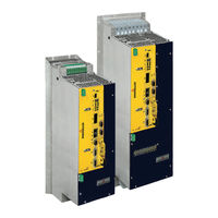
Baumuller b maXX 5500 Instruction Handbook Manual (316 pages)
Basic Units/Power Modules with Servo Controller
Brand:
Baumuller
| Category:
Servo Drives
| Size: 13 MB
Table of Contents
Table of Contents
3
1 General
7
Information on the Instruction Handbook
7
Key to Symbols
7
Limitation of Liability
8
Copyright Protection
9
Other Applicable Documents
9
Spare Parts
10
Disposal
10
Guarantee Provisions
10
Customer Service
10
Terms Used
10
List of Other Applicable Documents
11
2 Safety
13
Contents of the Instruction Handbook
13
Changes and Modifications to the Device
13
Usage for the Intended Purpose
14
Risk Assessment According EU Directive
15
Wiring of the Power Cables
16
Responsibility of the Operating Company
17
Protection Devices
17
Training of the Personnel
18
Personal Protective Equipment
19
Special Hazards
20
Fire Fighting
21
Safety Equipment
22
Conduct in Case of Danger or Accidents
22
Signs and Labels
23
Signs and Labels BM5X3X
25
Signs and Labels BM5X4X, BM5X5X
26
Signs and Labels BM5X6X, BM5X7X
27
3 Technical Data
29
Dimensions
29
Dimensions BM551X
30
Dimensions BM552X
31
Dimensions BM552X-F/C
31
Dimensions BM552X-S/Z
31
Dimensions BM5X3X
32
Dimensions BM553X-A/F
32
Dimensions BM553X-S/Z
32
Dimensions BM553X-C
33
Dimensions BM563X-F
33
Dimensions BM5X4X
34
Dimensions BM554X-S/Z
34
Dimensions BM554X-A/F, BM564X-A/F
35
Dimensions BM564X-FXX9
36
Dimensions BM5X5X
37
Dimensions BM555X-S/Z
37
Dimensions BM555X-A/F
38
Dimensions BM565X-FXX9, BM575X-FXX9
39
Dimensions BM575X-FXX9-RYY
40
Dimensions BM565X-ZXX9-[RYY], BM575X-ZXX9-[RYY]
41
Dimensions BM5X6X
42
Dimensions BM5X7X
46
Weight
48
Operating Requirements
49
System Types
49
Requirements to the Energy Supply / Supply System
50
Motor Requirements
52
Required Environmental Conditions
53
Correction Factors if the Operating Conditions Are Changed
54
Operating Altitude
54
Environmental Temperature
55
Supply Voltage
55
Coherence between Rated Current and Peak Current
57
Calculation of the Thermal Rms Current
57
Coherence between Peak Current and Rated Current
57
Cooling
59
Electrical Data Basic Units
61
Electrical Data BM55XX Universal Units
61
Electrical Data BM5X1X Universal Units
61
Electrical Data BM5X2X Universal Units
64
Electrical Data BM553X Universal Units
68
Electrical Data BM554X Universal Units
72
Electrical Data BM555X Universal Units
76
Electrical Data BM556X Universal Units
80
Electrical Data BM557X Universal Units
84
Electrical Data BM56XX Acceleration Units
87
Electrical Data BM563X Acceleration Units
87
Electrical Data BM564X Acceleration Units
89
Electrical Data BM565X Acceleration Units
93
Electrical Data BM566X Acceleration Units
95
Electrical Data BM57XX Continuous Current Unit
97
Electrical Data Power Modules
101
Electrical Data BM552X Power Module
101
Electrical Data BM553X Power Module
103
Electrical Data BM554X Power Module
105
Electrical Data BM555X Power Module
107
Electrical Data BM556X Power Module
109
Electrical Data BM557X Power Module
111
Additional Data Referring to Water-Cooled Brake Resistors
113
Output Frequency Dependent Continuous Current Derating BM5XXX
119
Output Frequency Dependent Maximum Current Derating BM56XX
120
4 Design and Operation
121
Design
121
Type Plate
123
Type Code
124
Explanation Type Code
124
Display and Operation Elements
128
Display/Operating Elements Controller BM52XX, BM53XX
128
7-Segment Display Controller
129
LED Display Controller
130
LED Display Fieldbus
131
Setting the IP Address with Address Switches
133
5 Transport and Packaging
139
Safety Notes for Transport
139
What to Observe When Transporting
139
Transport Inspection
140
Unpacking
140
Disposal of the Packaging
140
6 Mounting
141
Safety Notes
141
Preparing for Mounting
144
Drilling Patterns
145
Drilling Patterns BM551X
145
Drilling Patterns BM552X
146
Drilling Patterns BM553X
146
Drilling Patterns BM5X4X
147
Drilling Patterns BM5X5X
147
Drilling Patterns BM5X6X
148
Drilling Patterns BM5X7X
149
Mounting Instructions
151
Requirements Mounting Plate for Cold Plate
158
Connecting the Water Cooler
158
Instruction Handbook B Maxx BM5500, BM5600, BM5700
159
7 Installation
159
Safety Notes
159
Voltage Test
161
Demands on the Power Supply
161
Requirements to the Connecting Cables
163
Protection of the Device and the Cable
163
PE Connection and RCD Compatibility
164
Installation Requirements with Regard to EMC
164
Avoid Bearing Currents
165
Requirements for the Motor Temperature Sensors
167
Installation Procedure
168
Wiring Diagrams
170
Connection Diagrams Without Controller Connections
171
BM55XX, BM56XX, BM57XX (Basic Units)
171
BM55XX, BM56XX, BM57XX Power Module
174
Connection of Several Devices to the DC Link Without Using the Signal Bus
177
Terminal Overviews
179
Terminals BM551X
180
Terminals BM552X
181
Terminals BM553X, BM563X
182
Terminals BM554X, BM564X
183
Terminals BM555X, BM556X, BM565X, BM566X
184
Terminals BM566X, BM576X
185
Terminals BM5755
186
Terminals BM557X, BM5773
187
Electrical Connection Power Unit
189
Requirements for the Screwing
192
Controller Terminals
193
8 Operation
217
Operating Concept
218
Release Signals
218
Power on Switching Frequency / DC Link Charging
219
Power Supply Switch-On Frequency BM551X and BM552X
219
Power Supply Switch-On Frequency BM5X3X to BM5X7X
219
Calculation of the Maximum Permitted External Capacitance
220
Effects of the Different Charging Circuits
221
Table of Charging Times
221
Monitoring
222
Ethercat
223
Fieldbus Communication
223
Varan
225
Canopen
227
Powerlink
229
9 Maintenance
231
Safety Notes
231
Environmental Condition
232
Inspection Intervals - Maintenance Notes
232
Periodic Maintenance
234
Repairs
236
10 Troubleshooting and Fault Correction
237
Behavior in Case of Malfunctions
237
Monitoring Functions
238
Fault Detection
243
Error Handling
244
11 Accessories and Spare Parts
245
Cabling
246
Cables Power Supply-Device
246
Cables Device-Motor
248
Hybrid Cable Device-Encoder-Motor
250
Control Voltage Supply/Signal Cable
256
Encoder Cables
256
Connecting Cable for Resolver
258
Connecting Cable for Encoders with HIPERFACE
259
Connecting Cable for Encoder with Endat ® or SSI
260
Connecting Cable for Encoder with Endat ® 2.2
261
Connecting Cable for Sine/Square-Wave Incremental Encoder
263
Connection Cable Add-On Modules
264
Fuses
266
Fuses BM551X
268
Fuses BM552X
268
Fuses BM5X3X
271
Fuses BM5X4X
272
Fuses BM5X5X
274
Fuses BM5X6X
278
Fuses BM557X
282
UL Fuse in the Ballast Circuit
283
Extra-Low Voltage Protection
283
Mains Filters
284
Block Diagram of Filter for Mains Applications (Simplified)
284
Baumüller Mains Filter Type Code
284
Required Mains Filter Environmental Conditions
284
Electrical Data Mains Filter
285
Mains Filter Selection
287
Power Chokes
288
Baumüller Accessories
292
Shielding Clamp
292
Accessories Ethernet/Ethercat ® /VARAN/POWERLINK
292
Accessories - Canopen
293
Service Interface Cable
293
Toroidal Cores
294
Spare Parts
295
12 Shutdown, Storage
297
Safety Instructions
297
Requirements to the Executing Personnel
298
Shutdown
298
Demounting
298
Storage Conditions
299
Recommissioning
300
13 Disposal
301
Safety Notes
301
Disposal Facilities/Authorities
303
Appenidx a - Abbreviations
305
Appenidx B - Declaration of Conformity
307
Table of Figures
309
Index
311
Overview of Revisions
313
Instruction Handbook B Maxx BM5500, BM5600, BM5700
313
Document No.: 5.13008.10 of
314
Advertisement
Advertisement
Related Products
Baumuller b maXX 3000
Baumuller b maXX 5100
Baumuller b maXX 5300
Baumuller BM3200
Baumuller BM3300
Baumuller b maXX BM5500
Baumuller b maXX BM5600
Baumuller b maXX BM5700
Baumuller BM5100 Series
Baumuller BM5300 Series
Baumuller Categories
Control Unit
Engine
Controller
Portable Generator
Media Converter
More Baumuller Manuals
Login
Sign In
OR
Sign in with Facebook
Sign in with Google
Upload manual
Upload from disk
Upload from URL