Table of Contents
Advertisement
Quick Links
BUSH
General Description:
operated portable receivers, each using seven transistors and one crystal
diode, and covering the Long and Medium wavebands.
range provides electrical bandspread of the high frequency end of the
Medium
waveband.
only in presentation.
Wavebands:
band:
187-S70 m. (160S to S2S kc/s.).
1430 kc/s.).
Battery: One 9-volt Ever Ready type PP9 or Drydex type DT9.
battery consumption is IS mA. quiescent and 2S mA. at average listening
level.
Transistors (Mullard Type):
(AFII7) I.F. amplifier.
amplifier.
VTS
Push-pull output.
Crystal Diode: CDl (OA90) Detector.
Earpiece Socket: A socket is provided at the side of the receiver into
which may be plugged an earpiece of 20-1000-ohms impedance.
tively, this socket may be used with an external loudspeaker of Is-ohms
impedance.
Tape Recording: No special provision has been made, but the earpiece
socket provides a low-impedance output source to which a tape recorder may
be conducted.
about I S ohms.
muted when using this method of recording.
CAPACITOR
DRIVE DRUM
RADIO SERVICING
Models TR130 and TR130D are battery
Both
models
L.W. band:
VT3 (AFII7) I.F. amplifier.
(OC81D)
Driver
The connecting lead should be terminated with a resistor of
It should be noted that the internal loudspeaker will be
Models TR 130 and TRI30D
are
electrically
1070-1900 m. (280 to IS8 kc/s.).
B.S. band:
VTl
(AFII7) Mixer/oscillator.
stage.
VT6
F42
DRIVE CORn
106
An additional
identical,
differing
187-210 m. (160S to
VT 4 (OC71) Audio
(OC81),
VT7
Alterna
M.W.
The
VT2
(OC81)
Advertisement
Table of Contents

Related Manuals for Bush TR130


Summary of Contents for Bush TR130
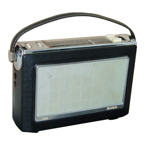
- Page 1 RADIO SERVICING BUSH Models TR 130 and TRI30D Models TR130 and TR130D are battery General Description: operated portable receivers, each using seven transistors and one crystal diode, and covering the Long and Medium wavebands. An additional range provides electrical bandspread of the high frequency end of the Medium waveband.
- Page 2 BUSH Dismantling: Place the cabinet face downwards, remove the detachable base, then remove the battery. Separate the two halves of the cabinet by releasing the two fasteners contained within the mouldings, then lift the back (Note: Dismantling to this stage will permit the R.F. align...
- Page 3 RADIO SERVICING signals into the aerial socket; a o·l-fLF. capacitor for I.F. lllJection, and an 8'2 kO-resistor for temporarily desensitising the receiver under conditions of interference. If the cabinet back is removed, R.F. alignment may be carried out without taking the chassis out. The chassis must be withdrawn, however, for I.F.
- Page 4 BUSH FRONT CHASSIS F4 4 PRINTED WIRING BOARD...
- Page 5 PUSH BUTTON SWITCH 5 HOWN f:::J 1'\ ..POSITION VIEwED FIICM SIDE ...5 .. .] ' (T. 2 ) DRIVER TRlM SfORHER OUTPUT T .I TRANSFORMER VIEWED VIEWED FROM osc. COl l fROM FROM TOP VIEWED IL8-LI0) CIRCUIT DIAGRAM-BUSH MODELS TRI30 AND TRI30D...
Need help?
Do you have a question about the TR130 and is the answer not in the manual?
Questions and answers