
Subscribe to Our Youtube Channel
Related Manuals for Jet JHBS916


Summary of Contents for Jet JHBS916
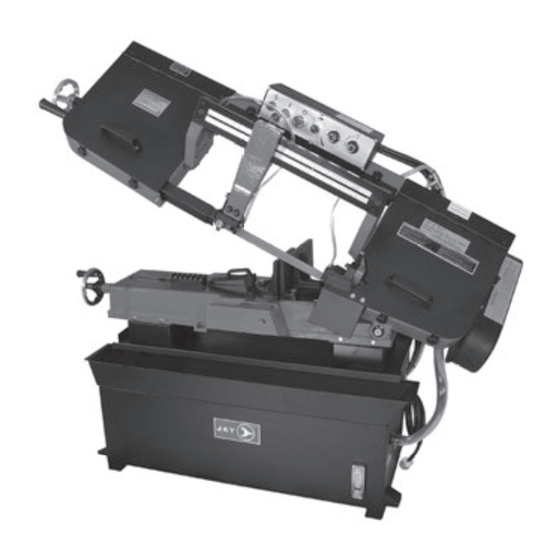
- Page 1 MANUAL 9" x 16" 1-1/2 HP 4 Speed Belt Drive Bandsaw Prod. No. 222335 Mod. No. JHBS916 ®Registered trademark of JET Equipment & Tools Ltd. M13-HT222335 www.jetgroupbrands.com...
-
Page 2: Table Of Contents
Warranty Policy JET makes every effort to assure that its products meet high quality standards and warrants to the retail consumer/purchaser of our products that each product is free from defects in material and workmanship. JET offers a TWO YEAR LIMITED WARRANTY on this product. -
Page 3: Safety Rules
WARNING For Your Own Safety Read Operator’s Manual Before Operating Saw Safety Rules a) Wear eye protection. b) Do not remove jammed cutoff pieces until blade has stopped and power has been disconnected. c) Maintain proper adjustment of blade tension, blade guides, and thrust bearings. d) Adjust movable guide to just clear workpiece. -
Page 4: Operating Instructions
Operating Instructions The Selection of Saw Blades 1. Check Coolant: Low coolant level causes Cutting foaming and high blade temperatures. Dirty or Material weak coolant can clog pump, causes crooked <3mm >5mm >50mm >100mm >150mm >200mm cuts, low cutting rate and permanent blade Sawblade <0.12"... - Page 5 www.jetgroupbrands.com...
-
Page 6: Single Phase
Single Phase 7. Make sure the teeth of the new blade are pointing in the direction of travel. If necessary, turn the blade inside out. Refer to the wiring drawing inside the electrical box and on page 5 for proper motor and transformer 8. - Page 7 Now tighten the nut at the back of the left hand wheel (A-1). Check blade tension during the performance of item 12. If proper tension has not been attained, loosen the nut at the back of the wheel (A-1) again and turn blade tension wheel CCW so the scale line is nearer to the 2,000 mark to the left of the scale.
- Page 8 Adjusting Blade Guide Brackets 4. Loosen the three bolts (A - Fig.5) located on the top of the tracking nuts. The blade guides should be set as close to the vise 5. Tracking adjustment is accomplished by either jaws as possible. The right blade guide bracket, is loosening or tightening three adjusting nuts not adjustable and is set at the factory to clear the (B - Fig.5).
- Page 9 Automatic Shut-Off Adjustment The motor should shut off immediately after the blade has cut through the material and just before the head comes to rest on the horizontal stop bolt. If the machine continues to run after the workpiece has been fully cut, locate and adjust the micro switch mounting plate (part #45) downward.
- Page 10 Vise Adjustment To position the moveable vise jaw: 1. Turn vise handwheel (A – Fig.10) 1/2 turn counter-clockwise. 2. Move rack block (B – Fig.10) to desired location by sliding along the bed. Place the rack block onto the rack. 3.
- Page 11 Changing Speeds Your machine is provided with four speeds. To change speeds, proceed as follows: 1. Disconnect the machine from the power source. 2. Loosen and remove knob, (A) Fig.12, and swing belt and pulley guard (B) to the side of the machine.
-
Page 12: Parts List
Parts Breakdown / Prèsentes diréctives Qty. Qty. Ref. Part No. Description Ref. Part No. Description Qté. Qté. PDNJHBS9161 Base / Socle PDNJHBS91632 Pivot Shaft / Axe de pivotement PDNJHBS9161-1 Wire Protector / Protège-fils 32-1 PDNJHBS91632-1 Washer / Rondelle Hex. Cap Bolt / Vis d’assemblage à tête PDNJHBS9161-2 Power Cord / Cordon d’alimentation PDNJHBS91632-2... - Page 13 Parts Breakdown / Prèsentes diréctives Qty. Qty. Ref. Part No. Description Ref. Part No. Description Qté. Qté. PDNJHBS91663 Washer / Rondelle M12 PDNJHBS916100 Hex. Cap Bolt / Boulon hexagonal 63-1 PDNJHBS91663-1 LockWasher / Rondelle frein M12 100-1 PDNJHBS916100-1 Washer / Rondelle M8 Vise Jaw - Left 100-2 PDNJHBS916100-2 Lock Washer / Rondelle frein M8...
-
Page 14: Replacement Parts
PDNJHBS916161-1 Switch With Key / Ensemble interrupteur Vous pouvez commander des pièces de rechange auprès du distributeur PDNJHBS916162 Switch / Interrupteur de votre localité ou en vous adressant directement à JET. Lorsque vous Emergency Stop Switch PDNJHBS916163 commandez des pièces de rechange, n’oubliez jamais de fournir les Interrupteur d’arrête de secours... -
Page 15: Parts Breakdowns
www.jetgroupbrands.com... - Page 16 www.jetgroupbrands.com...
Need help?
Do you have a question about the JHBS916 and is the answer not in the manual?
Questions and answers