
Related Manuals for Det-Tronics FlexSight LS2000


Summary of Contents for Det-Tronics FlexSight LS2000
- Page 1 Instructions FlexSight™ LS2000 Line-of-Sight Infrared Hydrocarbon Gas Detector 95-8714...
-
Page 2: Table Of Contents
Table of Contents APPLICATION ......1 ALIGNMENT......24 Overview . -
Page 3: Application
It can be used as a stand-alone RS-485 Modbus communication. Alarm and detector, or as part of a larger facility protection fault relays are available as an option. system using other Det-Tronics equipment. Standard system outputs for the LON version are as follows: – HART communication –... -
Page 4: Operation Overview
OPERATION OVERVIEW DETECTABLE GASES The LS2000 is capable of detecting most hydrocarbon THEORY OF OPERATION gases and vapors including methane, propane, and T he LS2 0 0 0 transmit ter module uses a butane. Gas type and other operational parameters are Xenon flash lamp to produce a collimated IR selected via HART, Modbus, or LON communication. - Page 5 Table 1—LFL-m to PPM-m Conversion Cloud Path Cloud Cloud Concentration (v/v, by Length Concentration Concentration LFL-m ppm-m volume) (LFL) (ppm) per ISO/NFPA 497 per IEC Methane 100% 5.0% 4.4% 50000 50000 Methane 100% 5.0% 4.4% 50000 100000 Methane 100% 5.0% 4.4% 50000 150000...
-
Page 6: Optional Relays
OPTIONAL RELAYS strength, status, and configuration parameters such as alarm set points, heater settings, gas The LS2000 can be furnished with factory type, etc. installed relays — two programmable alarm relay outputs and one fault relay output. All 2. Dynamic lamp power – The link enables relays are sealed and provide form C (NO/NC) the system to optimize lamp power per the contacts. -
Page 7: Operation
OPERATION INTERNAL MAGNETIC SWITCH / CALIBRATION LINE TERMINAL An internal magnetic switch is provided for resetting latched alarms and initiating field zero calibration. See Figure 2 for switch location. The same functions can be accomplished remotely by installing a switch (momentary closure) between the CAL and 0V COM terminals on the LS2 0 0 0 receiver. -
Page 8: Operating Modes
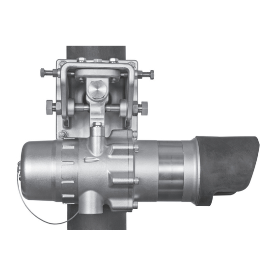
TRANSMITTER RECEIVER A2647 Figure 3— Identification of Transmitter and Receiver Modules OPERATING MODES Normal The LS2000 has three operating modes: warm- After warm-up mode is completed, the device up, normal (measuring / monitoring), and automatically enters the Normal mode, and all calibrate. -
Page 9: Heater Control
HEATER CONTROL Table 6—Typical LS2000 Window Temperature Rise (Degrees C) for Various Heater Settings and Ambient Temperatures The LS2000 optics in both transmitter and receiver are heated to provide moisture and ice AMBIENT TEMPERATURE LS2000 Window resistance. These heaters are microprocessor Temperature Rise (C) -55°C -40°C... - Page 10 Table 5—LS2000 Receiver Fault Conditions 4-20mA Output Relays Status User Default Advanced Fault Relay Defined 4-20 Fault Yellow - Solid for 10 seconds, De-energized (Open Loop) followed by 1 Pulse Detection RAM Fault De-energized Yellow - Solid Disabled Detection Data Flash Fault De-energized Yellow - Solid Disabled...
- Page 11 Table 5—LS2000 Receiver Fault Conditions (Continued) Status Condition Recommended Action 4-20 Fault The 4-20 mA output loop is not functioning Check field wiring, termination points, and resistance (Open Loop) properly; the output mA level does not of the 4-20 mA loop. Ensure that the 4-20 mA output match the output set point of the device.
-
Page 12: Status And Fault Indication
SPECIFICATIONS STATUS AND FAULT INDICATION Status and fault conditions are indicated using OPERATING VOLTAGE (Both Modules)— the 4–20 mA analog signal output. Signaling 24 Vdc nominal. Operating range is 18 to 30 Vdc. modes include two predefined modes, and a Ripple cannot exceed 0.5 volts P-P. - Page 13 The transmitter has an oval shaped field of view with a minimum 0.8 degree tolerance along CAUTION the horizontal axis and a minimum 1.5 degree tolerance along the vertical axis (Det-Tronics When the LS2000 Gas Detector is used in verified). conjunction with an appropriate certified...
- Page 14 TEMPERATURE RANGE— WIRING— Operating: –55°C to +75°C (–67°F to +167°F) Field wiring screw terminals are UL/CSA rated Relay version: –55°C to +65°C (–67°F to +149°F) for up to 14 AWG shielded wire, and are DIN/ VDE rated for 2.5 mm wire.
- Page 15 (12.7) (12.7) (12.7) (12.7) 10.8 (27.5) 10.8 (27.5) 14.3 16.1 (36.3) (40.8) (18.5) (20.1) (17.9) (17.8) (20.6) (19.1) A2660 A2659 Figure 4—Mounted Dimensions of LS2000 Transmitter Figure 5—Mounted Dimensions of LS2000 Receiver in Inches (cm) in Inches (cm) 95-8714...
-
Page 16: Important Safety Notes
IMPORTANT SAFETY NOTES LIABILITIES Th e m a n u f a c t u r e r ’s wa r r a n t y f o r CAUTION this product is void, and all liability The wiring procedures in this manual for proper function of the system is a r e i n t e n d e d t o e n s u r e p r o p e r irrevocably transferred to the owner or... -
Page 17: Installation
LS2000. In addition, the physical and fire Det-Tronics Field Service Engineering group hazard properties of the vapor, such as vapor routinely provides jobsite application surveys density and flashpoint, should be identified and... - Page 18 System Mounting Elevation Snow and Ice in Ambients Below –20°C In all cases, the modules should be installed The heated optics on both modules will at the same elevation above grade to ensure melt snow or ice on the windows in ambient that alignment capability and foul weather temperatures down to approximately –20°C.
-
Page 19: Module Mounting Recommendations
Areas Prone to Earthquakes When using a vertitcal post a square stock pole is recommended. In the event of an earthquake, there is a chance that the modules will become misaligned with The post can be set into the ground or attached respect to each other. - Page 20 3 METERS MAXIMUM HEIGHT IMMOVABLE STRUCTURE 1 METER OR BELOW FROST LINE A2666 NOTE: INSTALLATIONS NEAR MAXIMUM HEIGHT TYPICALLY REQUIRE BRACING TO ENSURE NO MOVEMENT OF THE LS2000 DETECTOR. Figure 8—Example of Bracing Added to Vertical Mounting Poles for Increased Robustness of LS2000 Installation Figure 10—LS2000 Gas Detector Mounted to Flat Surface Figure 9—LS2000 Gas Detector Mounted to Vertical Post (Refer to "Dimensions"...
-
Page 21: Replacing An Existing Model Opecl With An Ls2000
REPLACING AN EXISTING MODEL OPECL 24 VDC POWER SUPPLY REQUIREMENTS WITH AN LS2000 Calculate the total gas detection system power consumption rate in watts from cold start-up. Flat Surface Mount Select a power supply with adequate capability An optional adapter plate (part number 012718- for the calculated load. -
Page 22: Power Wiring Size And Maximum Length
3. Normally, nothing smaller than 18 AWG, 1.0 NOTE is recommended by Det-Tronics for R e f e r t o “A l a r m R e l a y s ” i n t h e LS2000 power cabling. - Page 23 NOTE For proper HART communication, it is required that an analog signal loop resistance of 250 to 500 ohms be present at the receiver analog output terminals. For LS2000 systems using HART communication, the maximum wiring distance is 2,000 feet. No external resistance needs to be added to the transmitter wiring for proper HART operation.
- Page 24 0V COM SPARE 0V COM SPARE +24 VDC 0V COM +24 VDC 0V COM 0V COM +24 VDC 0V COM +24 VDC SHIELD SHIELD SHIELD SHIELD INTR B INTR A INTR B INTR A INTR GND INTR GND SHIELD SHIELD RS-485 A SHIELD SHIELD...
- Page 25 0V COM SPARE +24 VDC 0V COM 0V COM +24 VDC +24 VDC 0V COM 0V COM +24 VDC SHIELD SHIELD SHIELD SHIELD COM1B COM2B 250 TO 500 INTR B INTR A OHMS COM1A COM2A INTR GND SHIELD SHIELD SHIELD SHIELD INTR B INTR A...
-
Page 26: Startup
STARTUP ALIGNMENT When the LS2000 is installed and wired as OVERVIEW described in the “Installation” section, it is ready The LS2000 modules must be properly aligned for commissioning. If the application requires before normal operation will be attained. that specific changes be made to the factory settings, HART communication will be required. -
Page 27: Alignment Procedure
ALIGNMENT PROCEDURE 1. Ensure that the system modules are located within the specified separation range and securely fixed to the support structures. Bypass all external gas alarm devices that are connected to the receiver outputs. 2. Ensure that the system modules are installed with their windows at approximately the same height above grade. - Page 28 STEP 1: CENTER CROSS HAIRS ON TARGET USING ADJUSTMENT BOLTS ON MOUNTING PLATE (POSITION A). STEP 2: ROTATE SCOPE 180°. ALIGNMENT ERROR CAUSES CROSS HAIRS TO MOVE TO POSITION B. STEP 3: ADJUST ALIGNMENT SCREWS ON SCOPE TO PLACE CROSS HAIRS AT POSITION C. STEP 4: ROTATE SCOPE 180°...
-
Page 29: Aperture Kit For Short Range Applications
APERTURE KIT FOR SHORT RANGE RECOMMENDATIONS FOR USING THE APPLICATIONS HART FIELD COMMUNICATOR T he S ho r t Range A per ture K it enables WARNING successful application of the LS2000 gas The LS2000 does not use Intrinsically detector at short separation distances (5–15 Safe circuitry for connection to the HART meters for the short range model and 30–40 475 Communicator. -
Page 30: Gain Level Check
GAIN LEVEL CHECK (Optional) A gain of 1 indicates that the system may be near saturation (signal strength is too high). If It is necessary to complete the alignment the gas gain number = 1 and the Active avg procedure before checking the gain level. or Ref avg numbers are greater than 1500, HART or Modbus communication is required to use the aperture kit to reduce signal. -
Page 31: Calibration
CALIBRATION Upon initiation, the LS2000 automatically performs the zero calibration adjustment, and then signals CALIBRATION OVERVIEW with a green LED when this operation is complete. Span calibration is not required. The LS2000 Calibration Using Magnetic Switch supports non-intrusive field zero calibration, although routine calibration is normally not The LS2000 receiver provides an onboard required. -
Page 32: Maintenance
LS2000 safety manual. NOTE Det-Tronics provides two functional check Refer to the LS2000 Safety Manual, options for the LS2000. The test film method number 95-8727 , for specific requirements provides a basic functional check as described and recommendations applicable to in step 20 of the basic alignment procedure. -
Page 33: Troubleshooting
TROUBLESHOOTING A Fault status is indicated by a yellow LED and also by the 4-20 mA output. Refer to Table 9 for assistance in correcting malfunctions with the LS2000 Detector. Table 9—Troubleshooting Guide Fault Condition Corrective Action Low 24 Volts 24 Vdc operating voltage is out of range. -
Page 34: Replacing Ls2000 Transmitter/Receiver Electronics Module
Turn the retainer ring by CAUTION hand to loosen the module. See Figure 29. Only Det-Tronics authorized personnel are allowed to perform this repair. 3. Carefully remove the old module by extracting it straight out from the bulkhead. - Page 35 Receiver 10. Upon completion of zero calibration, verify Fully tighten the retainer ring on the receiver proper operation by performing an “optical module, then tighten the set screw to prevent test film test” and also a “beam block test” the ring from being turned. (see steps 20 and 21 in the “Basic Alignment Procedure”...
-
Page 36: Device Repair And Return
DEVICE REPAIR AND RETURN ORDERING INFORMATION The LS2000 IR Hydrocarbon Gas Detector is When ordering, please refer to the LS2000 Model not designed to be repaired in the field. If a Matrix: problem should develop, first carefully check for proper wiring, programming and calibration. If it ALIGNMENT EQUIPMENT is determined that the problem is caused by an Part Number... - Page 37 LS2000 MODEL MATRIX MODEL DESCRIPTION LS2000 Line-of-Sight Infrared Gas Detector TYPE MATERIAL Stainless Steel TYPE CONDUIT ENTRY THREAD TYPE 3/4" NPT, 4 Port Receiver, 2 Port Transmitter Metric M25, 4 Port Receiver, 2 Port Transmitter TYPE OUTPUT None (Transmitter only) Eagle Quantum Premier (EQP) 4-20 mA, RS485, HART (Receiver or Kit) 4-20 mA, RS485, HART w/Optional Relays (Receiver or Kit) –...
-
Page 38: Appendix A - Fm Approval Description
APPENDIX A FM APPROVAL DESCRIPTION The following items, functions, and options describe the FM approval. APPROVAL Line-of-Sight Infrared Hydrocarbon Gas Detector, Model LS2000. Receiver with or without Relays Class I, Div. 1, Groups B, C & D (T4). Class I, Div. 2, Groups A, B, C & D (T4). Class II/III, Div. - Page 39 RESPONSE TIME T90: 2 seconds (2.5 LFL-meters applied). Note: Add 1 second to response time for EQP compatible models NOTES Approval of the LS2000 does not include or imply approval of the apparatus to which the detector may be connected and which processes the electronic signal for eventual end use. In order to maintain an approved system, the apparatus to which the detector is connected must also be approved.
-
Page 40: Appendix B - Csa Certification Description
APPENDIX B CSA CERTIFICATION DESCRIPTION The following items, functions, and options describe the CSA certification. APPROVAL Line-of-Sight Infrared Hydrocarbon Gas Detector, Model LS2000. Receiver with Relays Class I, Div. 1, Groups B, C, & D (T4). Tamb = –55°C to +75°C. Class I, Div. - Page 41 RESPONSE TIME T90: 2 seconds (2.5 LFL-meters applied). Note: Add 1 second to response time for EQP compatible models NOTES Approval of the LS2000 does not include or imply approval of the apparatus to which the detector may be connected and which processes the electronic signal for eventual end use. In order to maintain an approved system, the apparatus to which the detector is connected must also be approved.
-
Page 42: Appendix C - Atex Approval Description
• The Model LS2000 has an ambient temperature rating of –55°C to +75°C. • Only suitable certified Ex d or Ex e (as applicable) cable entries, adapters, and blanking elements are to be used, including 1/2 inch NPT, 3/4 inch NPT, M20 and M25 sizes, with IP66/67 rating. • Flameproof joints are not user serviceable; contact Det-Tronics Service. • Seven special fasteners are provided for the Transmitter electronics module, M8 bolts per ISO 965 with M6 head, SST with a yield strength of 483 N/mm (70,000 PSI). The tightening torque in an opposing order is 19 Nm (169 inch-pounds) per flange bolt. - Page 43 ATEX Standards: EN 60079-29-4: 2010 Performance Approved for Methane, Butane, and Propane. EN 60079-0: 2012 +A11:2013 EN 60079-1: 2014 EN 60079-7: 2015 EN 60079-28:2007 EN 60529:1991+A1:2000 EN 50270: 2015 EN 50271: 2010 Conforms to: Low Voltage Directive: 2014/35/EU, EMC Directive: 2014/30/EU, ATEX Directive: 2014/34/EU, WEEE 2002/96/EC.
- Page 44 NOTES Approval of the LS2000 does not include or imply approval of the apparatus to which the detector may be connected and which processes the electronic signal for eventual end use. In order to maintain an approved system, the apparatus to which the detector is connected must also be approved.
-
Page 45: Appendix D - Iecex Approval Description
0.4 to 0.5 Nm. • The metal housings of the Model LS2000 Gas Detector must be electrically connected to earth ground. • Flameproof joints are not user serviceable; contact Det-Tronics Service. • Seven special fasteners are provided for the Transmitter electronics module, M8 bolts per ISO 965 with M6 head, SST with a yield strength of 483 N/mm2 (70,000 PSI). The tightening torque in an opposing order is 19 Nm (169 inch-pounds) per flange bolt. - Page 46 WARNING Always ensure that the detector/junction box hazardous (classified) location ratings are applicable for the intended use. WARNING Potential electrostatic charging hazard on brow. Use caution when servicing in an explosive environment. Additional Safety Notes: • For ambient temperatures below –10°C, use field wiring suitable for the expected conditions, and for ambient temperatures above +60°C, use field wiring and cable glands suitable for 15°C above the maximum expected conditions.
-
Page 47: Appendix E - Additional Approvals
TEMPERATURE HUMIDITY VIBRATION ENCLOSURE LS2000 C/IP66/IP67 Relevant tests according to “Standard for Certification No. 2.4.” Location classes for LS2000 (Shaded areas show Det-Tronics approved location classes) COLUMN 1 COLUMN 2 MAIN AREAS ON BOARD Pump room, Open TYPE LOCATION WITHIN MAIN AREA... - Page 48 INMETRO UL-BR 15.0742X Ex db eb IIC T4 Ex db IIC T4 IP66/67 –50°C ≤ Tamb ≤ +75°C (for Ex db eb version) –55°C ≤ Tamb ≤ +75°C (for Ex db version) RUSSIA & KAZAKHSTAN VNIIFTRI CERTIFICATE OF CONFORMITY TO “TP TC 012/2011” TC RU C-US.
-
Page 49: Appendix F - Hart Communication
APPENDIX F HART COMMUNICATION Digital communication with the LS2000 is necessary to monitor internal status and to modify the factory settings. This appendix provides guidance on establishing HART communication, and describes the communication menu structure when using the LS2000 with the HART Handheld Communicator. - Page 50 LS2000 HART MENU STRUCTURE This section displays the menu trees for the LS2000. The Menu tree shows the primary commands and options available when using menu selections. 95-8714...
- Page 51 6) Day 7) Year 8) Write Protect CONNECTIONS AND HARDWARE The HART Communicator can interface with the LS2000 from the control room or from any wiring termination point in the analog output signal loop. To communicate, connect the HART communicator in parallel with the LS2000 analog signal or load resistor.
-
Page 52: Appendix G - Eagle Quantum Premier Model
If necessary, consult factory for further suggested cable types. IMPORTANT Det-Tronics recommends the use of shielded cable (required by ATEX) to prevent external electromagnetic interference from affecting field devices. IMPORTANT For best fault isolation performance, the maximum LON wiring length should not exceed 1600 feet (500 meters). - Page 53 CONFIGURATION AND OPERATION Configuration of the EQP LS2000 is accomplished using Det-Tronics Safety System Software (S that is running on the EQP Operator Interface Station (OIS). The LS2000 should be configured as a Line-Of-Sight Gas Detector (LS2000). 95-8714...
- Page 54 Supported gas types for the LS2000 include Methane (Default), Propane, and Butane. The range for LS2000 high and low alarms is 0.5–3.0 LFL-m. The beam block delay time can be set from 60–3600 seconds. Alarms can be set for latching or non-latching operation. The real time clock in the LS2000 receiver is automatically set by the LON network approximately once per hour.
- Page 55 ONBOARD HART INTERFACE The on-board HART interface is functional on the EQP LS2000, however, it should not be used to select the gas type, alarm levels, or the beam block delay time because the LON will overwrite these values. All EQP device configuration should be performed using the S program.
- Page 56 SETTING NETWORK ADDRESSES Overview of Network Addresses Each IR gas detector on the EQP LON must be assigned a unique address. Addresses 1 to 4 LS2000 are reserved for the EQP controller. Valid addresses for field devices including gas detectors LS2000 are from 5 to 250.
- Page 57 LS2000 Address Switches Address switches for are located within the device enclosure. Refer to Figure G-2 for switch LS2000 location. WARNING Disassembly of the LS2000 housing and removal of the front electronics module from the bulkhead is required to gain access to the network address switches. Power should be removed from the detector before disassembly.
- Page 58 Switch Access Procedure NOTE It is strongly recommended to document all LS2000 gas detector network addresses as well as the addresses of all other LON devices on the Address Identification Chart before disassembling and programming the LS2000 gas detectors. Removal of the retaining ring and the front electronics module of the LS2000 IR gas detector from the bulkhead is required in order to gain access to the network address DIP switch.
- Page 59 SINGLE SOLENOID DUAL SOLENOIDS CH 1 CH 2 CH 3 CH 4 CH 5 CH 6 CH 7 CH 8 RELAY 2 RELAY 3 RELAY 4 RELAY 1 DIGITAL INPUTS RELAY 5 RELAY 6 RELAY 7 RELAY 8 95-8714...
- Page 60 Phone: 952.946.6491 Corporate Office © 2019 Detector Electronics Corporation. All rights reserved. Toll-free: 800.765.3473 6901 West 110 Street Det-Tronics manufacturing system is certified to ISO 9001— Fax: 952.829.8750 Minneapolis, MN 55438 USA the world’s most recognized quality management standard. det-tronics@det-tronics.com www.det-tronics.com...
Need help?
Do you have a question about the FlexSight LS2000 and is the answer not in the manual?
Questions and answers