Table of Contents
Advertisement
Quick Links
Advertisement
Table of Contents

Subscribe to Our Youtube Channel
Related Manuals for Rohde & Schwarz TSMA


Summary of Contents for Rohde & Schwarz TSMA
- Page 1 ® R&S TSMA Autonomous Mobile Network Scanner User Manual (;ÛÆ:2) 1177561002...
- Page 2 ® This manual describes firmware version FW 01.32.00.04 and later of the R&S TSMA. ® It describes the following R&S TSMA models and options: ● ® R&S TSMA (1514.6520.20) ● ® TD-SCDMA Option R&S TSME-K20 (1510.0079.02) ● ® WCDMA Scanner Option R&S TSME-K21 (1514.6820.02)
-
Page 3: Table Of Contents
Release Notes and Open Source Acknowledgment (OSA)..........9 Key Features........................10 2 Safety Information................11 3 System Overview................. 12 R&S TSMA Base Unit....................12 R&S TSMA-BP Battery Pack Unit - Optional Unit.............13 4 Instrument Tour..................15 Front Panel........................15 Rear Panel........................15 Status LEDs......................... 18 4.3.1... - Page 4 6.6.2 Installation ROMES/NESTOR Mobile Device Drivers........... 40 7 Configuring the R&S TSMA..............43 Accessing the R&S TSMA..................43 7.1.1 Start the R&S TSMA Web-GUI..................43 7.1.2 Establish a Remote Desktop Connection..............44 Changing Password of R&S TSMA................46 Measurement Setup....................48 Measurement Modes....................49 7.4.1...
- Page 5 8.4.1 Backup.......................... 83 8.4.2 Restore..........................84 Master Image....................... 84 8.5.1 Prepare a TSMA Image Stick / TSMA Recovery Stick..........85 8.5.1.1 USB Stick Preparation....................86 8.5.1.2 Copy File Contents on the USB Stick (Image Stick)............. 88 8.5.1.3 Copy File Contents on the USB Stick (Recovery Stick)..........88 8.5.2...
- Page 6 Check the Cabling between Scanner Unit and CPU Unit........102 Verify Scanner Port LAN Settings................103 No Navigation Data in R&S ROMES / R&S NESTOR..........104 No RF Data.........................105 Remote ViCom Sample App on Smart Phone could not connect with R&S TSMA ............................ 106 R&S TSMA Web-GUI not accessible................108 Annex....................111 A Usage of the Web GUI................
- Page 7 ® Contents R&S TSMA A.4.2 Install...........................122 Update........................123 Backup........................123 Restart........................124 Help..........................125 B Introduction to Remote ViCom Sample App........126 Overview........................126 Requirements......................126 B.2.1 General Requirements....................126 B.2.2 Preparation........................126 Usage......................... 127 B.3.1 Connection Establishment..................127 B.3.1.1 Connection Type Selection..................127 B.3.1.2...
- Page 8 ® Contents R&S TSMA User Manual 1177.5610.02 ─ 11...
-
Page 9: Preface
1.1.1 Getting Started Manual Introduces the R&S TSMA and describes how to set up and start working with the product. Includes basic operations, typical measurement examples, and general infor- mation, e.g. safety instructions, etc. A printed version is delivered with the instrument. -
Page 10: Key Features
The R&S TSMA enhances such solutions, providing the user with accurate insight into the RF environment. The R&S TSMA combines the technology of the R&S TSME ultra-compact drive test scanner with a high-performance Intel processor. -
Page 11: Safety Information
R&S TSMA 2 Safety Information The product documentation helps you use the R&S TSMA safely and efficiently. Follow the instructions provided here and in the printed "Basic Safety Instructions". Keep the product documentation nearby and offer it to other users. -
Page 12: System Overview
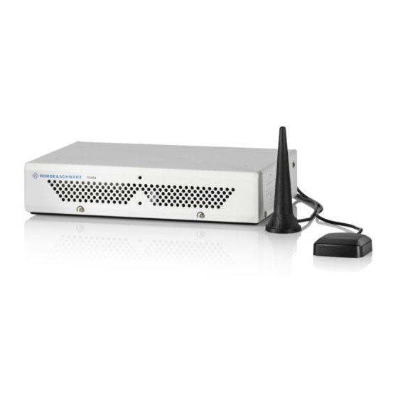
TSMA R&S TSMA Base Unit 3 System Overview 3.1 R&S TSMA Base Unit The R&S TSMA base unit consists of the following components: ● R&S TSME drive test scanner unit ● Integrated Intel PC with a high-performance i5 processor and an embedded Micro- soft Windows Operating System (Windows 7, 64 bit). -
Page 13: R&S Tsma-Bp Battery Pack Unit - Optional Unit
3.2 R&S TSMA-BP Battery Pack Unit - Optional Unit The R&S TSMA-BP Battery Pack Unit features two rechargeablehot-swapable batter- ies (R&S TSMA-BAT, 1523.8021.03), which can be charged directly if the battery pack is connected to an external power supply. Alternatively, a separate battery charger (R&S TSMA-BC2, 1523.8015.02) can be used for recharging the batteries. - Page 14 TSMA R&S TSMA-BP Battery Pack Unit - Optional Unit The recharging of the batteries is only allowed via the separate charger (R&S TSMA- BC2, 1523.8015.02) or via an external power supply. In this case, the batteries must be inside the R&S TSMA.
-
Page 15: Instrument Tour
TSMA Rear Panel 4 Instrument Tour 4.1 Front Panel The front panel of the R&S TSMA does not provide any connectors or control elements for operation. Figure 4-1: R&S TSMA - Front Panel 4.2 Rear Panel The following figure provides an overview of the control elements and the connectors on the rear panel of the instrument. - Page 16 18. AUX Connector The AUX connector can be used to synchronize the R&S TSMA with the external 10 MHz reference frequency output of a signal generator or to synchronize multiple R&S TSMA/TSME in a MIMO setup; the Sync cable is necessary.
- Page 17 5120 x 2880 pixel) The LAN connector provides a high-speed 100 Mbit Ethernet interface with an RJ 45 connector using IPv4. It is used to connect the R&S TSMA to a host PC in a local net- work. The LAN interface can be used for Remote Control / Remote Desktop Connections. In this case, the device must not be in the "Scanner Only"...
-
Page 18: Status Leds
The port with the label "2 " is the WLAN antenna port. Connect one of the accessory WLAN / Bluetooth antennas to this SMA connector. RESTORE With the RESTORE button, it is possible to bring the R&S TSMA back to factory default. Loss of user data after RESTORE Executing restore brings the R&S TSMA irreversible back to the condition of delivery or... - Page 19 NESTOR)", on page 99 This description of the STATE LED is based on the initial firmware. If the R&S TSMA is working in a specific mode, e.g. ROMES, NESTOR, ViCom or QualiPoc, the STATE LED may be used for these applications.
-
Page 20: Scan Link
® Instrument Tour R&S TSMA Status LEDs 4.3.2 SCAN LINK Table 4-1: SCAN Link LED1 (link) states and their meaning LED state Description No link yellow, blinking Identify scanner module (TSME Device Manager test), (synchronous with SCAN LED and SCAN Link LED2) -
Page 21: S Tsma Option Concept
TSMA Technology Options 5 R&S TSMA Option Concept The R&S TSMA scanner consists of the R&S TSMA hardware and a set of (specified) technology and band options when it comes from the factory. 5.1 Technology Options Technology options allow the R&S TSMA to scan the input based on a specific technol- ogy, for example, LTE. -
Page 22: Band Options
These configurations limit the number of bands that can be measured in parallel. You can reconfigure the bands for each measurement as desired. Upgrade options are available to increase the bandwidth of the R&S TSMA from a limi- ted number of bands to full bandwidth. -
Page 23: Preparing For Use
® Preparing for Use R&S TSMA Unpacking the Instrument 6 Preparing for Use Risk of injury and instrument damage The instrument must be used in an appropriate manner to prevent electric shock, fire, personal injury, or damage. ● Do not open the instrument casing. - Page 24 Retain the original packing material. If the instrument needs to be transported or ship- ped later, you can use the material to protect the control elements and connectors. Accessory list The following items are included with shipment of the R&S TSMA: ● SCAN Link interconnection cable (SCAN <-> SCAN) ●...
-
Page 25: Connecting External Devices
The following external devices must be connected before connecting the power supply. To select the correct connectors, refer to Figure 4-2. 1. Connect the SCAN ports of scanner and PC unit of the R&S TSMA. User Manual 1177.5610.02 ─ 11... - Page 26 ® Preparing for Use R&S TSMA Connecting External Devices Figure 6-2: Connection between scanner unit and internal PC unit 1 = SCAN Link connector (CPU port) 2 = SCAN Link connector (Scanner Port) 3 = SCAN Link interconnection cable Note: Use only the LAN interconnection cable (R&S No. 5016.1890.00) for con- necting the SCAN ports.
-
Page 27: Connecting Power Supply
Connecting Power Supply Display Port Adapter to VGA 6. Connect a LAN cable to the LAN port if you want to use the R&S TSMA via Remote Desktop or as distributed system. (optional) 7. Connect external devices/storage devices and test mobile phones to USB 2.0/USB 3.0 ports. -
Page 28: Connecting The R&S Tsma-Bp Battery Pack Unit
Alternatively, it is possible to power the R&S TSMA via the R&S TSMA-BP Battery Pack Unit. To use the R&S TSMA with the battery pack, the following steps must be performed. 1. Insert the batteries into the R&S TSMA. Note: The R&S TSMA may be used only with closed battery cover. - Page 29 1 = Connectors for R&S TSMA base unit Figure 6-7: R&S TSMA Base Unit (bottom side) 1 = Connectors for R&S TSMA-BP 3. Move the R&S TSMA base unit to the front side (2) until the connectors are locked. User Manual 1177.5610.02 ─ 11...
- Page 30 2 = R&S TSMA 3 = Lock (front side) 5. Via the cable (3), you have to connect the DC IN connector on the R&S TSMA (1) with the TSMA connector (7 pins) on the R&S TSMA-BP (2). User Manual 1177.5610.02 ─ 11...
- Page 31 The cable plugs are marked at both sides with a red spot. Figure 6-11: Cable Connected at the DC IN (1) of the R&S TSMA, this red spot must face upwards, at the TSMA connector (2) of the R&S TSMA-BP it must face downwards.
- Page 32 7-pin to 4-pin adapter cable (5) and connect the 4-pin socket with AC power supply (R&S TSMA-Z1, R&S No. 1523.8450.02). If a valid DC input voltage is applied to DC IN of the R&S TSMA-BP, the R&S TSMA is powered from this external DC supply and the batteries inside the R&S TSMA-BP are charged.
-
Page 33: Connecting An Additional R&S Tsme For Mimo Support
1 = DC IN connector R&S TSMA Base Unit 2 = TSMA connector R&S TSMA-BP Battery Pack Unit 3 = DC power interconnection cable (R&S TSMA Base Unit <-> R&S TSMA-BP Battery Pack Unit) 4 = DC IN connector R&S TSMA-BP Battery Pack Unit 5 = Adapter cable (7-pin to 4-pin) 6 = DC IN (TSMA-Z1 resp. -
Page 34: Mimo 2X2 Upgrade Kit
TSMA Connecting an Additional R&S TSME for MIMO Support Figure 6-14: R&S TSMA with R&S TSMA-BP battery pack unit and mounted R&S TSME (front side view) Figure 6-15: R&S TSMA with R&S TSMA-BP battery pack unit and mounted R&S TSME (rear side view, emphasized is USB 3.0 lower port) -
Page 35: Mounting R&S Tsme
Holder TSMA+PB/TSME (1523.8415.00) ● VS 7985/ISR-M3X5-A4-PA (3565.7210.009) ● VS 7985/ISR-M2.5X5-A4-PA (1148.2617.00) ● Installation Instruction R&S TSMA-ZM (1523.8438.00) ● Documents folder (5001.8913.00) Figure 6-16: Some items of the upgrade kit 1 = SYNC cable for TSME 2 = Holders 3 = Turnlock fasteners 6.4.2 Mounting R&S TSME... - Page 36 Connecting an Additional R&S TSME for MIMO Support Figure 6-17: Holders screwed on the devices 2. Fasten the R&S TSME onto the R&S TSMA, attaching the R&S TSME as shown in the following figure. Figure 6-18: Mounting R&S TSME on R&S TSMA 3.
-
Page 37: Connecting Test Mobile Phones
2 = Connection TSME LAN port to R&S TSPC-2UL USB 3.0 to LAN Adapter (RJ45 Patch cable shiel- ded CAT5E) 3 = Connection lower USB 3.0 port of the R&S TSMA (the port marked in the figure displaying the rear side of the combination TSMA+BP/TSME) to R&S TSPC-2UL USB 3.0 to LAN Adapter... -
Page 38: R&S Tsma Driver Update
R&S TSMA Driver Update 6.6 R&S TSMA Driver Update ● The package "R&S TSMA ThinkPad USB LAN Setup 1.00" is required to extend the R&S TSMA with an additional scanner LAN port for MIMO LTE operation. ● The packages "R&S TSMA Samsung Android USB Setup 1.00" and "R&S TSMA Qualcomm Driver Setup 1.00"... - Page 39 R&S TSMA Driver Update Figure 6-20: R&S Software Distributor opening page 3. Select "Local Installation" and click "Next". The opened page shows the contents of the "R&S TSMA Driver Update Package 1.00". Figure 6-21: Contents of the R&S TSMA Driver Update Package...
-
Page 40: Installation Romes/Nestor Mobile Device Drivers
Figure 6-22: Installed package Make sure, that the IPv4 address 192.168.2.1 is not used by any other LAN adapter. The R&S TSME IP address has to be set to 192.168.2.x to support the R&S TSMA MIMO measurements. How to change the address: see "R&S TSME Ultra Compact Drive Test Scanner User Manual"... - Page 41 R&S TSMA Driver Update Figure 6-23: R&S Software Distributor opening page 2. Select "Local Installation" and click "Next". The opened page shows the contents of the "R&S TSMA Driver Update Package 1.00". Figure 6-24: Contents of the R&S TSMA Driver Update Package...
- Page 42 Preparing for Use R&S TSMA R&S TSMA Driver Update 3. Select "R&S TSMA Samsung Android USB Setup 1.00" and "R&S TSMA Qual- comm Driver Setup 1.00"and click "Install". 4. Close the installation. The tool installs the required packages. For more, see ROMES UE Application.pdf included in the delivered R&S ROMES DVD.
-
Page 43: Configuring The R&S Tsma
7.1 Accessing the R&S TSMA There are different ways to access the R&S TSMA. ● Local operation To use the R&S TSMA as an ordinary PC, an external monitor, mouse and key- board have to be connected to the R&S TSMA. ● Remote access The remote access to the R&S TSMA can be realized via the following options. -
Page 44: Establish A Remote Desktop Connection
Accessing the R&S TSMA 1. Connect the R&S TSMA LAN port with the host PC port. 2. Use the R&S TSMA default IP settings, that is, the DHCP Client. The R&S TSMA and the remote host PC automatically negotiate the IP address. - Page 45 LAN: IP address is assigned by the host PC 5. Click "Connect". 6. Enter the password 894129 and click "OK". 7. The remote desktop connection is established. The R&S TSMA can be controller as a standard PC. User Manual 1177.5610.02 ─ 11...
-
Page 46: Changing Password Of R&S Tsma
TSMA Changing Password of R&S TSMA 7.2 Changing Password of R&S TSMA To change the default password (default PW: 894129) of R&S TSMA, proceed as fol- lows. After changing the password, additional steps has to be performed for "Autolo- gin". - Page 47 ® Configuring the R&S TSMA R&S TSMA Changing Password of R&S TSMA 5. Fill in the fields (1) and click "Change password" (2). Enable Autologin After changing the password, change the password also in "Autologin" settings. To change the "Autologin" settings, proceed as follows.
-
Page 48: Measurement Setup
3. If the required application is not yet installed, install the application according to the procedures described in Chapter 8.2, "Software Installation", on page 69. 4. Select the measurement mode in the R&S TSMA Web-GUI; the modes are descri- bed in Chapter 7.4, "Measurement Modes", on page 49. -
Page 49: Measurement Modes
The other software applications, that is, the R&S NESTOR, R&S ROMES and Quali- Poc are installed only if ordered. 7.4.1 Remote ViCom Server Mode The connection between the Remote Vicom server on the R&S TSMA and the client application (Remote ViCom client) on the handheld device can be realized via Blue- ®... -
Page 50: Qualipoc Mode
® Configuring the R&S TSMA R&S TSMA Measurement Modes 3. Connect the tablet/smartphone with the R&S TSMA WLAN AP. Measurement To run measurements, the requirements for operating the rViCom Sample App have to be fulfilled, see Chapter B.2.1, "General Requirements", on page 126. - Page 51 R&S TSMA Measurement Modes Figure 7-2: Scan for NCM 6. Touch "[Disconnected]", touch the TSMA scanner in the list, for example, "TSMA-900012", and then touch to accept the pairing request. Figure 7-3: Pair NCM Figure 7-4: Bluetooth pairing request 7. Touch the scanner again in the list to connect to the scanner.
-
Page 52: Nestor And Nestor Probe Mode
7.4.3 NESTOR and NESTOR Probe Mode In the "NESTOR" mode, which can be started only if the R&S NESTOR is installed, otherwise is dimmed, the R&S NESTOR software is hosted on the R&S TSMA. The selection of a valid workspace file is required. - Page 53 ● Only for "NESTOR Probe" mode The R&S TSMA and the external PC must be connected via WLAN or the LAN port of the R&S TSMA. Import of NESTOR Workspace File Importing of the R&S NESTOR workspace file is an additional requirement for operat- ing in the "NESTOR"...
-
Page 54: Romes Mode
Measurement Modes 7.4.4 ROMES Mode In the "ROMES" mode, the ROMES software is hosted on the R&S TSMA and the selection of a valid workspace file is required. The ROMES mode is only displayed if the ROMES setup has been executed (see Chapter 8.2.4, "R&S ROMES... -
Page 55: Pc Mode
The "PC Mode" is used for software update of the R&S TSMA. 7.4.6 Scanner Only Mode In the scanner only mode, only the scanner unit of the R&S TSMA is active, the PC unit is in stand-by mode. In this case, the scanner unit (R&S TSME) can be connected via the SCAN port 1 with a host PC. - Page 56 With the setting "Auto Power On", the R&S TSMA starts automatically, when a DC power supply is connected. With the setting "Remember Last State", the R&S TSMA uses the last state before the R&S TSMA was powered off. Additionally. the setting "Auto Power Off" can be activated. In this case, the R&S TSMA is powered off, if a DC power supply is no longer available.
-
Page 57: Update And Restore
1. Connect mouse and keyboard to USB ports and a monitor to the mini display port. The setup file must be available on the R&S TSMA or on a USB stick. 2. Switch on the R&S TSMA via the power button. - Page 58 ® Update and Restore R&S TSMA Firmware Update 7. The package dialog lists all the available packages in the setup. Normally, this dia- log can be skipped without any changes. Select "Automatic Reboot". 8. Press "Install >". Note: Do not switch off or unplug from power while running firmware/software update.
-
Page 59: Remote Installation Of The Setup File
Using LAN Connection ● Connect the LAN port of the R&S TSMA with the host PC LAN port. The LAN port is marked with LAN. The default IP setting of this port is "DHCP client". For details on how to configure the remote PC, contact your network administrator. - Page 60 Switch on the R&S TSMA via power button. ● On the remote PC, search for the R&S TSMA WLAN and connect to the network. The necessary access parameters can be found on a label at the bottom of the device.
- Page 61 All packages, which you need to install are already pre-selected. 6. Click "Next>". 7. After a while, all R&S TSMA devices in the network are listed in the "Device List" dialog. Devices with a firmware version > 02.xx.yy.zz are only listed, if the device is in "PC Mode"...
-
Page 62: Installation Using A Usb Stick
Installation Using a USB Stick The setup will be initiated via the web GUI of the R&S TSMA. In this case, the setup file must be available in the root directory of a USB stick, which is connected to the R&S TSMA. - Page 63 R&S TSMA Firmware Update 2. Switch on the R&S TSMA via power button. 3. Copy the setup file onto a USB memory stick. a) For firmware installation: Copy the firmware setup file TSMAx-Setup-<Version>.exe into the root directory of the stick.
- Page 64 9. After the installation of all firmware/software packages, the R&S TSMA reboots. Starting with firmware version 03.00.10.02, the mode LED changes to blinking green (selftest). 10. After the reboot, call the R&S TSMA web GUI. The status text Installation successful is displayed. User Manual 1177.5610.02 ─ 11...
- Page 65 ® Update and Restore R&S TSMA Firmware Update 11. About one minute after the operating system is up again, the flash of the main- board firmware starts. The microcontroller flash is indicated like following: STATE LED = white, SCAN LED = off...
-
Page 66: Calling R&S Tsma Web Gui
R&S TSMA Firmware Update 8.1.3 Calling R&S TSMA Web GUI The R&S TSMA web GUI has to be loaded prior to executing firmware / software setup. ● Remote from a WLAN connected device Start the web browser and enter the following URL: http://192.168.1.10... -
Page 67: Checking Mode Of Operation
TSMA Firmware Update 8.1.4 Checking Mode of Operation In order to execute the setup on the R&S TSMA, the mode of operation has to be "PC Mode". 1. Open the R&S TSMA web GUI. Use one of the following options. - Page 68 ® Update and Restore R&S TSMA Firmware Update 3. If a different mode is activated, navigate to "Configuration" > "System" > "Mode", select the "PC Mode" and press the "Submit" button. User Manual 1177.5610.02 ─ 11...
-
Page 69: Software Installation
4. Reload the web GUI after changing the mode, and ensure that the "Mode of Oper- ation" is "PC Mode". The R&S TSMA is ready for firmware update / software installation. 8.2 Software Installation Following software components are available for installation on the R&S TSMA. -
Page 70: Remote Vicom Server Software
The update of the Remote ViCom installation could be neglected for other modes of operation (NESTOR, ROMES, QualiPoc). The installed version of the Remote ViCom server on the R&S TSMA need to match with the applied version of rViCom client API on the remote Android device. -
Page 71: Vicom Server Remote Installation
® Update and Restore R&S TSMA Software Installation 3. All subsequent steps are similar to local firmware installation, see Chapter 8.1.2.1, "Local Execution of the Setup File", on page 57, step 7 and following. Do not switch off or unplug from power while running firmware/software update. -
Page 72: Vicom Server Installation Using A Usb Stick
® Update and Restore R&S TSMA Software Installation 3. All subsequent steps are similar to remote firmware installation, see Chap- ter 8.1.2.2, "Remote Installation of the Setup File", on page 59, step 4 and follow- ing. 8.2.1.4 ViCom Server Installation Using a USB Stick Follow the general instructions in Chapter 8.1.2.3, "Installation Using a USB... -
Page 73: R&S Nestor Software
Stick", on page 62, step 7 step 8.2.2 R&S NESTOR Software Only execute the dedicated NESTOR setup for R&S TSMA. The setup file is named TSMAx_NESTOR_Setup-<Version>.exe. 8.2.2.1 Preparation 1. Download the software setup file TSMAx_NESTOR_Setup-<Version>.exe from the Rohde & Schwarz FTP server respectively NESTOR CD-ROM. -
Page 74: Nestor Local Installation
® Update and Restore R&S TSMA Software Installation 8.2.2.2 NESTOR Local Installation Follow the general instructions in Chapter 8.1.2.1, "Local Execution of the Setup File", on page 57, step 1 step 1. Open the Windows Explorer and execute the NESTOR setup file "TSMAx_NES- TOR_Setup-<Version>.exe". -
Page 75: Nestor Installation Using A Usb Stick
® Update and Restore R&S TSMA Software Installation 3. All subsequent steps are similar to remote firmware installation, see Chap- ter 8.1.2.2, "Remote Installation of the Setup File", on page 59, step 4 and follow- ing. 8.2.2.4 NESTOR Installation Using a USB Stick Follow the general instructions in Chapter 8.1.2.3, "Installation Using a USB... -
Page 76: Swissqual Diversityprobe For Qualipoc Software
7 step 8.2.3 SwissQual DiversityProbe for QualiPoc Software Version 15.2.0.25 or greater must be installed on the R&S TSMA. Only execute the dedicated QualiPoc setup forR&S TSMA. The setup file is named DiversityProbe4QP-DeploymentKit-<Version>.exe. 8.2.3.1 Preparation 1. Download the QualiPoc setup file DiversityProbe4QP-DeploymentKit-<Version>.exe from the Rohde &... -
Page 77: Diversityprobe For Qualipoc Local Installation
® Update and Restore R&S TSMA Software Installation 8.2.3.2 DiversityProbe for QualiPoc Local Installation Follow the general instructions in Chapter 8.1.2.1, "Local Execution of the Setup File", on page 57, step 1 step 1. Open the Windows Explorer and execute the QualiPoc setup file DiversityProbe4QP-DeploymentKit-<Version>.exe. -
Page 78: Diversityprobe For Qualipoc Installation Using A Usb Stick
® Update and Restore R&S TSMA Software Installation 3. All subsequent steps are similar to remote firmware installation, see Chap- ter 8.1.2.2, "Remote Installation of the Setup File", on page 59, step 4 and follow- ing. 8.2.3.4 DiversityProbe for QualiPoc Installation Using a USB Stick Follow the general instructions in Chapter 8.1.2.3, "Installation Using a USB... -
Page 79: R&S Romes Setup
7 step 8.2.4 R&S ROMES Setup Only execute the dedicated ROMES setup for R&S TSMA. The setup file is named TSMA-Romes-Setupxyy.exe (Example: TSMA-ROMES-Setup490p1.exe). If R&S ROMES is used together with test mobile phones, a device driver update is required. For details, seeChapter 6.6, "R&S TSMA Driver... -
Page 80: Romes Local Installation
® Update and Restore R&S TSMA Software Installation 2. Choose the way of installation and follow the instructions how to prepare. 8.2.4.2 ROMES Local Installation Follow the general instructions in Chapter 8.1.2.1, "Local Execution of the Setup File", on page 57,... -
Page 81: Romes Installation Using A Usb Stick
® Update and Restore R&S TSMA Software Installation 3. All subsequent steps are similar to remote firmware installation, see Chap- ter 8.1.2.2, "Remote Installation of the Setup File", on page 59, step 4 and follow- ing. 8.2.4.4 ROMES Installation Using a USB Stick Follow the general instructions in Chapter 8.1.2.3, "Installation Using a USB... -
Page 82: Options (Nestor, Tsma, Romes)
To change the operation mode, see "Mode of Operation" on page 115). 8.3.1 Installation of NESTOR Options In order to install R&S NESTOR options, perform the following steps. 1. Start the web GUI of the R&S TSMA. User Manual 1177.5610.02 ─ 11... -
Page 83: Installation Of Tsma Options
3. Add the license key code of a specific NESTOR option in the field "Install NESTOR Options" manually and click "Install". 8.3.2 Installation of TSMA Options In order to install TSMA scanner options, perform the followings steps. 1. Start the web GUI of the R&S TSMA. 2. Navigate to "Options" > "Install" Tab (see "Install Scanner Options"... -
Page 84: Restore
The color of the depends on the state of the WLAN AP. During the backup, do not interrupt the procedure or disconnect the power supply! 8.4.2 Restore With the RESTORE button it is possible to restore the system partition R&S TSMA to the user backup (see Chapter 8.4.1, "Backup",... -
Page 85: Prepare A Tsma Image Stick / Tsma Recovery Stick
Chapter 8.5.2, "Install the RSRecoveryCreator Tool ", on page 88). ● Capture a TSMA Image of the master device using the TSMA Image Stick (see Chapter 8.5.3, "Capture a TSMA Image (TSMA Image Stick)", on page 89). ● Create a TSMA Recovery Stick from a captured TSMA Image using the RSRecoveryCreator tool (see Chapter 8.5.4, "Create a TSMA Recovery... -
Page 86: Usb Stick Preparation
8.5.1.1 USB Stick Preparation In order to get a TSMA Image Stick / TSMA Recovery Stick out of a USB stick, the stick has to be formatted and made bootable. Format the USB stick 1. Plug the USB stick into the USB port the PC. - Page 87 ® Update and Restore R&S TSMA Master Image Figure 8-3 the drive 1 is selected. Figure 8-3: USB Stick drive and partition selection 4. To see the available partition of the selected drive use the list partition com- mand. The list of partitions appears.
-
Page 88: Copy File Contents On The Usb Stick (Image Stick)
The "Recovery Creator" application must be installed on PC. The RecoveryCreator_Setup_<version>.exe can be downloaded from https:// www.rohde-schwarz.com/software/tsma6/. This application allows to upload data from the TSMA Image Stick or hard disk to a Recovery Stick. User Manual 1177.5610.02 ─ 11... -
Page 89: Capture A Tsma Image (Tsma Image Stick)
88) to an USB 3.0 port of the R&S TSMA. 2. Reboot the R&S TSMA. The system will boot from the TSMA Image Stick. Figure 8-5: Boot TSMA Image Stick 3. In the TSMA Image Stick menu, click "Capture Image". - Page 90 Update and Restore R&S TSMA Master Image Figure 8-6: TSMA Image Stick menu 4. When the Status has changed to "Finished", click "OK" and then "Reboot". Figure 8-7: TSMA Image Stick - Image capturing finished User Manual 1177.5610.02 ─ 11...
- Page 91 ® Update and Restore R&S TSMA Master Image Figure 8-8: TSMA Image Stick menu - Reboot 5. Remove the TSMA Image Stick. The R&S TSMA will be rebooted. Figure 8-9: Rebooting R&S TSMA User Manual 1177.5610.02 ─ 11...
-
Page 92: Create A Tsma Recovery Stick
TSMA Image Stick in the directory \Device\Images. Figure 8-10: Captured Image Files on a TSMA Image Stick The TSMA Image Stick can now be used as source for the creation of a TSMA Recov- ery Stick (see Chapter 8.5.4, "Create a TSMA Recovery... - Page 93 Drive C: "BACKUP.wim" ● Drive D: "DATA.wim" The data source can be either the TSMA Image Stick or a PC storage location. 5. Press "Apply" to complete the selection and start file transfer onto the TSMA Recovery Stick. The selected TSMA image files are copied from the specified directory to the Recovery Stick (/Device/Images).
-
Page 94: Deploy A Tsma Image From A Tsma Recovery Stick
Deployment of a TSMA image requires a TSMA Recovery Stick containing the four master image files (GRUB.wim, SYSTEM.wim, DATA.wim, RECOVERY.wim). 1. Connect the TSMA Recovery Stick to an USB 3.0 port of the new R&S TSMA device. 2. Reboot the R&S TSMA. The R&S TSMA boots from the Recovery Stick and the start page of the Recovery Stick is displayed. - Page 95 Update and Restore R&S TSMA Master Image 3. In the "Recovery TSMA Progress" window, the current status of the recovery proc- ess is displayed. 4. After a successful recovery, remove the TSMA recovery stick. 5. The R&S TSMA will be rebooted.
-
Page 96: Troubleshooting
No remote access to the R&S TSMA via LAN port 9 Troubleshooting 9.1 No remote access to the R&S TSMA via LAN port If the R&S TSMA could not be accessed for remote control or remote desktop session via the LAN port, check following issues: Optical Check ►... - Page 97 R&S TSMA No remote access to the R&S TSMA via LAN port Figure 9-1: Web-GUI - Overview 3. Check the setting of the R&S TSMA LAN port (see Chapter A.2.2.4, "LAN", on page 119). The default setting is "DHCP". User Manual 1177.5610.02 ─ 11...
- Page 98 Figure 9-1). 2. Start the ping command. Type in the command line window ping <IP address of the R&S TSMA> and wait for the answer. If the R&S TSME does not answer, contact the system administrator or the R&S support.
-
Page 99: The Scanner Unit Could Not Be Loaded From Software (R&S Romes, R&S Nestor)
Sharing Center" > "Change Adapter Settings". 3. The entry TSMA LAN Connection must be available. Figure 9-2: TSMA LAN Connection 4. If the "TSMA LAN Connection" is not listed in the "Network Connections", a recov- ery of the R&S TSMA is recommended (see Chapter 8.4.2, "Restore",... - Page 100 ® Troubleshooting R&S TSMA The Scanner Unit could not be loaded from Software (R&S ROMES, R&S NESTOR) User Manual 1177.5610.02 ─ 11...
- Page 101 "Start the R&S TSMA Web-GUI", on page 43) and check the "Mode of Operation". ● If the Web-GUI is not accessible, continue with Chapter 9.8, "R&S TSMA Web- GUI not accessible", on page 108). ● If the "Mode of Operation" = "PC Mode", continue with step 3 ●...
-
Page 102: Check The Cabling Between Scanner Unit And Cpu Unit
Check the Cabling between Scanner Unit and CPU Unit ● IP Address : 192.168.0.2 If the R&S TSMA scanner can not be found, contact the R&S support. 6. Start the TSME Device Manager via the Windows Start menu. "Start > All Programs > TsmeTools > TsmeDeviceManager"... -
Page 103: Verify Scanner Port Lan Settings
Verify Scanner Port LAN Settings 9.4 Verify Scanner Port LAN Settings 1. Connect keyboard, mouse and monitor to the R&S TSMA. 2. Check the IP setting of the TSMA scanner connection. Navigate to "Windows" > "Control Panel" > "Network and Internet" > "Network and Sharing Center"... -
Page 104: No Navigation Data In R&S Romes / R&S Nestor
® Troubleshooting R&S TSMA No Navigation Data in R&S ROMES / R&S NESTOR a) Double-click the TSMA Scanner Connection entry and verify the following set- tings. ● IP address: 192.168.0.1 (static IP address) ● Jumbo Packet: 9014 Bytes 9.5 No Navigation Data in R&S ROMES / R&S NESTOR Check if the GPS antenna is connected to the correct port. -
Page 105: No Rf Data
Figure 9-8: R&S TSMA Antenna Cabling - RF 1 = RF antenna 2. Connect mouse, keyboard and monitor with the R&S TSMA for local operation. 3. Open the Web-GUI (Internet Explorer, URL: http://localhost) and change the "Mode of Operation" to "PC Mode". -
Page 106: Remote Vicom Sample App On Smart Phone Could Not Connect With R&S Tsma
If R&S TSMA is accessible via the TSME Device Manager, continue with step b) If R&S TSMA is not accessible via the TSME Device Manager, continue with Chapter 9.2, "The Scanner Unit could not be loaded from Software (R&S ROMES, R&S... - Page 107 Verify, that the tablet/smartphone is paired with the R&S TSMA. 10. For using the WLAN interface. Check on the remote device, if it is connected to the TSMA WLAN network / SSID: TSMA-<xxxxxx>. 11. Activate the "rViCom Server" mode in the R&S TSMA Web-GUI (see "Mode of...
-
Page 108: R&S Tsma Web-Gui Not Accessible
9.8 R&S TSMA Web-GUI not accessible If the R&S TSMAWeb-GUI is not accessible, perform the following steps to solve the problem. 1. For remote connection via WLAN, check if the TSMA WLAN is visible via your smartphone/tablet. ● If it is visible, continue with step ●... - Page 109 Update", on page 57). 8. Try again to start the Web-GUI locally on the R&S TSMA via Internet Explorer. If the Web-GUI can be started, continue with step If the Web-GUI can not be started, a complete restore must be performed (see Chapter 8.4, "User Backup and...
- Page 110 ® Troubleshooting R&S TSMA R&S TSMA Web-GUI not accessible 12. Check on your smartphone/tablet again, if the WLAN access point is now visible. If the WLAN access point is visible, continue with step If the WLAN access point is not visible, contact the R&S support.
-
Page 111: Annex
The "System" window consists of the following tabs. ● Overview........................111 ● Settings......................113 ● Info......................... 113 A.1.1 Overview The "Overview" tab displays the following basic settings of the R&S TSMA. Device Info........................112 └ Type......................112 └ Material No....................112 └ Serial No....................... - Page 112 Serial No. ← Device Info Serial number of the device Computer Name ← Device Info Computer name of the R&S TSMA (read-only). The name consists of a fixed part (TSMA) and a variable part (serial number). Example: R&S TSMA-<Serial Number>...
-
Page 113: Ip Settings
Battery Life Time ← Battery Info Estimated remaining battery life time. Mainboard Temperature ← Battery Info Current temperature of the mainboard. A.1.2 IP Settings The "IP Settings" tab displays the IP addresses of the R&S TSMA. Port........................113 SCAN Port (Int.)......................113 Ext.1........................113 WLAN AP (Overview).................... - Page 114 ® Usage of the Web GUI R&S TSMA Home └ Board.......................114 └ Mainboard..................... 114 └ Batterypack....................114 Scanner Info Displays IP and configuration settings of the scanner device. MAC Address ← Scanner Info MAC address of the scanner port. IP Address (Scanner) ← Scanner Info IP address of the scanner.
-
Page 115: Configuration
Auto Power ON ← Startup Settings The R&S TSMA starts automatically when power is applied at the DC IN connector of the R&S TSMA or at the DC IN connector of a connected R&S TSMA Battery Pack. Remember Last State ← Startup Settings The R&S TSMA remembers the last state before the DC power was removed. -
Page 116: Speaker
R&S TSMA Configuration When DC power is applied again at the DC IN connector of the R&S TSMA or at the DC IN connector of a connected R&S TSMA Battery Pack, the power state before power removal is recovered. Delayed System Start Configure the power on delay (in min) and press "Activate". -
Page 117: Bluetooth
● LAN........................119 ● Ext.1.......................120 A.2.2.1 Bluetooth The "Bluetooth" tab is used to configure the settings of the R&S TSMA Bluetooth adapter. As well this tab is used for pairing with an external BT device. Bluetooth Connection....................117 └ Status (Bluetooth).................. -
Page 118: Wlan Ap
The IP address can be assigned automatically via DHCP ("DHCP") or manually as fixed IP address ("Static"). IP Address (WLAN Client) ← WLAN Adapter Specify the IP address of the R&S TSMA Subnet Mask (WLAN Client) ← WLAN Adapter Specify the subnet mask for the R&S TSMA Default Gateway (WLAN Client) ←... -
Page 119: Lan
The IP address can be assigned automatically via DHCP ("DHCP") or manually as fixed IP address ("Static"). IP Address (LAN) ← LAN Connection Specify the IP address of the R&S TSMA. Subnet Mask (LAN) ← LAN Connection Specify the subnet mask for the R&S TSMA. -
Page 120: Lan Ext.1
Specify the DNS server. It is possible to specify a primary and a secondary DNS server. A.3 File Transfer The "File Transfer" window offers the following functions: ● Uploads and downloads of files to/from the R&S TSMA (File Transfer) ● Download of the Vicom sample application to an Android device. File Transfer........................ 121 └... -
Page 121: Options
R&S TSMA (D:\Upload). Note: The maximum file size for the upload is 100 MB. Download ← File Transfer Specifies the measurement data file which should be transferred from the R&S TSMA (D:\Download) to a connected device. User-defined Upload ← File Transfer Specifies the file (e.g. -
Page 122: Install
Start and expiration date of installed temporary license key Option Index Index number of the installed license key A.4.2 Install The "Install" tab is used to install various license key files on the R&S TSMA. Install NESTOR Options....................122 Install Scanner Options.................... -
Page 123: Update
R&S TSMA Backup A.5 Update The "Update" window allows to select and update the TSMA software and additional software components. Prerequisites for a Firmware/Software Update ● The setup file must be located in the root directory of the data stick. -
Page 124: Restart
● If there is a system failure, the system can be restored by pressing the "RESTORE" button. A.7 Restart The "Restart" window allows to restart the complete R&S TSMA and the scanner unit separately. System restart......................124 PowerCycle......................... 124 System restart To restart the R&S TSMA, click "Restart". -
Page 125: Help
® Usage of the Web GUI R&S TSMA Help A.8 Help The "Help" window displays the online help system of the R&S TSMA. User Manual 1177.5610.02 ─ 11... -
Page 126: B Introduction To Remote Vicom Sample App
Remote rViCom Server on the R&S TSMA (default) ● An installed Sample App on the Android device The version of the rViCom server on the R&S TSMA must match the version of the Sample App on the Android device. B.2.2 Preparation Before starting a scan or test, it is necessary to make sure that a connection can be established. -
Page 127: Usage
Start the Sample App on the Android device. B.3.1.1 Connection Type Selection To connect to the R&S TSMA Remote rViCom Server, it is either possible to use a WLAN connection or a Bluetooth connection. The selection of the connection type depends on the measurement task (see Chap- ter B.3.1, "Connection... - Page 128 ® Introduction to Remote ViCom Sample App R&S TSMA Usage Figure B-2: Active Server Discovery 3. If a server is found, the server will be connected and the name of the server is dis- played. Figure B-3: Successful Server Discovery 4.
-
Page 129: Gsm Rssi Scan
® Introduction to Remote ViCom Sample App R&S TSMA Usage The following scan types are available: ● GSM RSSI Scan Provides a GSM scan by selecting a band and radio channels ● WCDMA Top-N Pilot Scan Provides an UMTS scan by selecting a frequency band and the UARFCN ●... -
Page 130: Gsm Scan Results
® Introduction to Remote ViCom Sample App R&S TSMA Usage 3. Click "Start scan" to start the scan. B.3.2.2 GSM Scan Results The GSM scan result graph displays one column for each channel selected. The height of a column represents the RSSI value (in dBm). -
Page 131: Wcdma Top-N Pilot Scan
® Introduction to Remote ViCom Sample App R&S TSMA Usage B.3.3 WCDMA Top-N Pilot Scan B.3.3.1 WCDMA Top-N Pilot Preferences To start a WCDMA scan, the following steps must be performed. 1. Choose a frequency band. The minimum UARFCN of this band is set automatically. -
Page 132: Lte Top Signal Scan
® Introduction to Remote ViCom Sample App R&S TSMA Usage Figure B-8: WCDMA Scan Result View Below the graph the measurement preferences and the status are displayed. Parameters Displays the configured preferences for the WCDMA scan. Status Displays the measurement duration and the measurement rate. The status button dis- plays the following colored states. -
Page 133: Lte Top Signal Scan Results
® Introduction to Remote ViCom Sample App R&S TSMA Usage Figure B-9: Setting the LTE Preferences 2. If necessary, change the EARFCN according to your needs. Note: Due to processing issues, it is not possible to select more than one EARFCN. -
Page 134: Throughput Test Case
® Introduction to Remote ViCom Sample App R&S TSMA Usage Status Displays the measurement duration and the measurement rate. The status button dis- plays the following colored states. ● Green The measurement is running and measurement data are received. ●... -
Page 135: Rf Power Scan
® Introduction to Remote ViCom Sample App R&S TSMA Usage ● y-axis The y-axis displays the corresponding throughput value (kB/s) The blue line shows the measured values. The orange line represents the visualized average of all values. Figure B-12: Throughput Result View Below the graph the following throughput results are displayed. -
Page 136: Rf Power Scan Results
® Introduction to Remote ViCom Sample App R&S TSMA Usage Figure B-13: RF Power Scan References 2. Click "Start Test" to start the scan. B.3.6.2 RF Power Scan Results The result of the RF power scan is a spectrum of the frequency range set before with the following axes: ●... - Page 137 ® Introduction to Remote ViCom Sample App R&S TSMA Usage Status Displays the measurement duration and the measurement rate. The status button dis- plays the following colored states. ● Green The measurement is running and measurement data are received. ●...
-
Page 138: C Available Cellular Bands
The following cellular bands are available for selection for R&S TSMAs with a limited band option (see Chapter 5, "R&S TSMA Option Concept", on page 21). Table C-1: Available cellular bands for the R&S TSMA TSME Band Span Start [MHz] Stop [MHz] "TETRA"... - Page 139 ® Available Cellular Bands R&S TSMA TSME Band Span Start [MHz] Stop [MHz] span 2 2110 2200 "S-Band" span 1 2000 2020 span 2 2180 2200 "2600" span 1 2496 2690 "3500" span 1 3410 3490 span 2 3510 3590 "WiMAX 7.x"...
- Page 140 ® Available Cellular Bands R&S TSMA Band Name Included standardized bands UL low UL high DL low DL high Duplex CDMA2000/EV-DO Band Class 5 (450 MHz Band) "480" GSM 480 478.8 488.8 "700" WiMAX 7.A CDMA2000/EV-DO Band Class 19 (Lower 700 MHz Band)
- Page 141 ® Available Cellular Bands R&S TSMA Band Name Included standardized bands UL low UL high DL low DL high Duplex CDMA2000/EV-DO Band Class 12 (800 MHz PAMR Band) 3GPP WCDMA VI 3GPP WCDMA XIX 3GPP WCDMA XXVI LTE Band 27...
- Page 142 ® Available Cellular Bands R&S TSMA Band Name Included standardized bands UL low UL high DL low DL high Duplex LTE Band 9 (UMTS1700) 1749.9 1784.9 1844.9 1879.9 CDMA2000/EV-DO Band Class 4 1750 1780 1840 1870 (Korean PCS Band) "1800"...
- Page 143 ® Available Cellular Bands R&S TSMA Band Name Included standardized bands UL low UL high DL low DL high Duplex WiMAX 3.A 2496 2690 2496 2690 WiMAX 3.B 2496 2572 2614 2690 LTE Band 38 TDD 2570 2620 2570 2620 3GPP TDD incl.
- Page 144 ® Available Cellular Bands R&S TSMA Band Name Included standardized bands UL low UL high DL low DL high Duplex WiMAX 4.C 3300 3400 3300 3400 "TDD 3400" LTE Band 42 TDD 3400 3600 3400 3600 WiMAX 5L.A 3400 3600...
-
Page 145: Glossary: Abbreviations
® Glossary: Abbreviations R&S TSMA Glossary: Abbreviations Symbols 1xEvDO: Evolution - Data Optimized BTS: Base Transceiver Station CDMA: Code Division Multiple Access DHCP: Dynamic Host Control Protocol DL: Downlink DNS: Domain Name Service EARFCN: E-UTRA Absolute Radio Frequency Channel Number... - Page 146 ® Glossary: Abbreviations R&S TSMA PCI: Physical Cell ID RNTI: Radio Network Temporary Identifier RSCP: Received Signal Code Power RSRP: Reference Signal Received Power RSSI: Received Signal Strength Indication SC: Scrambling Code SSID: Service Set Identifier TD-SCDMA: Time Division - Synchronous Code Division Multiple Access...
-
Page 147: Index
Open source acknowledgment (OSA) ......... 9 Option Concept Band Options .............. 22 R&S NESTOR .............22 Technology Options ............ 21 R&S TSMA Option Concept ..........21 Release notes ..............9 Remote rViCom Requirements ............126 Usage ............... 127 Remote ViCom ..............126 RF Power Scan ...............
Need help?
Do you have a question about the TSMA and is the answer not in the manual?
Questions and answers