
Subscribe to Our Youtube Channel
Related Manuals for Rohde & Schwarz TSME6


Summary of Contents for Rohde & Schwarz TSME6
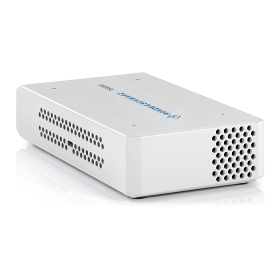
- Page 1 ® R&S TSME6 Ultracompact Drive Test Scanner User Manual (a00Q2) 4900003302 Version 06...
- Page 2 ® This manual applies to the following R&S TSME6 models and options: ● ® R&S TSME6 (4900.0004.02) ● ® Block IQ data R&S TSME6-K10 (4900.2459.02) ● ® WCDMA scanning R&S TSME6-K21 (4900.2188.02) ● ® ® CDMA2000 scanning R&S TSME6-K22 (4900.2165.02) ●...
-
Page 3: Table Of Contents
® Contents R&S TSME6 Contents 1 Safety and regulatory information............7 Safety instructions......................7 Labels on the product....................9 Korea certification class B..................10 2 Welcome....................11 Documentation overview....................11 2.1.1 Getting started manual....................11 2.1.2 User manuals and help....................11 2.1.3 Tutorials.........................11 2.1.4 Basic safety instructions....................11 2.1.5... - Page 4 3.1.7 Connecting R&S TSME6 with R&S TSMA6/6B-BP............32 3.1.8 Switching on or off R&S TSME6................... 32 3.1.9 Connecting the R&S TSME6 to a software application for the first time....... 32 Instrument tour......................35 3.2.1 Front panel view......................35 3.2.2 Rear panel view......................36 4 Option concept..................40...
- Page 5 ® Contents R&S TSME6 Solving other miscellaneous problems..............65 Contacting customer support..................69 8 Transporting..................70 9 Maintenance, storage and disposal........... 71 Cleaning........................71 Storage.........................71 Disposal........................71 Annex....................73 A Available cellular bands..............73 Index......................80 User Manual 4900.0033.02 ─ 06...
- Page 6 ® Contents R&S TSME6 User Manual 4900.0033.02 ─ 06...
-
Page 7: Safety And Regulatory Information
Intended use The R&S TSME6 is intended for efficient drive and walk tests with a maximum degree of freedom and upgradeability. With the ultracompact design and multiband and multi- technology support for simultaneous measurements, the scanner fulfills all require- ments for a state-of-the-art measurement tool. - Page 8 ® Safety and regulatory information R&S TSME6 Safety instructions Operating the product The product is intended for mobile use. The maximum weight of the product is provi- ded in the data sheet. If the product casing is not waterproof, use an adequate weather protection to carry the product outdoors with you.
-
Page 9: Labels On The Product
Labels on the casing inform about: ● Personal safety, see "Meaning of safety labels" on page 9 ● Product and environment safety, see Table 1-1 ● Identification of the product, see bottom label of the R&S TSME6. User Manual 4900.0033.02 ─ 06... -
Page 10: Korea Certification Class B
® Safety and regulatory information R&S TSME6 Korea certification class B Table 1-1: Labels regarding product and environment safety Labeling in line with EN 50419 for disposal of electrical and electronic equipment after the prod- uct has come to the end of its service life. For more information, see "Disposing electrical and... -
Page 11: Welcome
2.1.1 Getting started manual Introduces the R&S TSME6 and describes how to set up and start working with the product. Includes basic operations, typical measurement examples, and general infor- mation, e.g. safety instructions, etc. A printed version is delivered with the instrument. -
Page 12: Application Notes, Application Cards, White Papers, Etc
These documents deal with special applications or background information on particu- lar topics. www.rohde-schwarz.com/application/tsmx 2.2 Key features The R&S TSME6 sets standards in RF performance and usability. Outstanding key features are: ● Support of frequency range 350 MHz to 6.0 GHz, integrated multi GNSS ●... -
Page 13: Getting Started
3.1.2 Setting up indoors 3.1.2.1 Placing the product on a bench top If you want to set up the R&S TSME6 on a benchtop or prepare the R&S TSME6 for mobile use, proceed as follows. To place the product on a bench top 1. - Page 14 Rackmounting The R&S TSME6 can be installed in a 19 inch rack using a rack adapter kit for one to four R&S TSME6s (option R&S TSME6-Z2, R&S no. 4900.1030.02). The installation instructions are part of the adapter kit.
-
Page 15: Considerations For Test Setup
® Getting Started R&S TSME6 Preparing for use Figure 3-3: Rackmounting of 4 R&S TSME6s Figure 3-4: Rackmounting of 4 R&S TSME6s (reverse orientation of R&S TSME6s) 3.1.3 Considerations for test setup Electromagnetic interference (EMI) can affect the measurement results. -
Page 16: Connecting To Power
3.1.4.1 Connecting to a vehicle DC power supply via cigarette lighter The R&S TSME6 is delivered with a 12 V DC power supply cable with a cigarette lighter connector. 1. Check the rating of the vehicle DC power supply. It has to be 12 V. -
Page 17: Connecting To An Ac Power Supply
3. Insert the AC power plug into a power outlet with ground contact. 3.1.5 Putting into operation This section describes the basic steps to be taken when setting up the R&S TSME6 for the first time. User Manual 4900.0033.02 ─ 06... -
Page 18: Setting Up The Lan Connection To The Host Pc
Note: This is the IP address set by the R&S TSME Device Manager. ● "Static IP" operating mode IP address is manually set on PC and a static IP used on R&S TSME6 if the follow- ing conditions are met: –... - Page 19 PC LAN interfaces. Note: If a R&S TSME6 is shared with 2 or more PCs, and its stored IP address is not in the defined range above, this may lead in rare cases to IP conflicts. It is therefore recommended to respect this rule.
- Page 20 IP address 192.168.0.1 to the host PC or configure the host PC to obtain an IP address automatically ("Auto-IP"). To control the R&S TSME6 from the host PC, the LAN interface of the host PC must be configured as follows: 1.
- Page 21 ® Getting Started R&S TSME6 Preparing for use a) Use any "Auto-IP" operating mode. Select "Obtain an IP address automatically". b) Use "Static IP" operating mode. ● Select "Use the following IP address" (fixed IP, no dynamic range) ● IP address: 192.168.0.1 (recommended) ●...
- Page 22 Multicast IP address for TSME: 224.17.4.76 ● Multicast Address for TSME6: 239.192.1.7 ● IP-Address of TSME6 has to be allowed as well: 192.168.0.2 (example) Note: In "full auto-IP" operating mode, the IP address generated for the R&S TSME6 has to be allowed. ●...
-
Page 23: Connecting External Devices
If it is set correct by user, the firewall is in a good state. Connecting the R&S TSME6 to the host PC The R&S TSME6 has a built-in 1000BASE-T (802.3ab), 1 Gbit/s Ethernet interface. The host PC must have a separate 1 Gbit network interface card with an independent LAN connection. -
Page 24: Connecting A Kensington Lock
Chapter 3.1.4, "Con- necting to power", on page 16. ● Connect the PC or notebook LAN port to the LAN port of the R&S TSME6 as described in Chapter 3.1.5.1, "Setting up the LAN connection to the host PC", on page 18. -
Page 25: Enabling Untethered Dead Reckoning
"No Fix". 3.1.6 Connecting multiple R&S TSME6s to one host PC Due to the compatibility of R&S TSME and R&S TSME6, the combined usage of R&S TSME and R&S TSME6 devices in a LTE-MIMO setup is possible. -
Page 26: Using Two R&S Tsme6S In Parallel
Basic LTE MIMO measurements are possible with a single R&S TSME6, which can analyze two different transmission paths of a signal from two different transmit anten- nas. A single R&S TSME6 can determine the RSRP/Q and RS SINR results for both paths (see documentation of the measurement software for details). - Page 27 (MIMO extension option R&S TSME6-K300 installed by default) Required Connections 1. Connect the SYNC-cable (R&S TSME6-ZC2, R&S no. 4900.1800.02) to the Aux. connectors of all R&S TSME6 devices in this setup. Figure 3-7: SYNC-cable connected to Aux. connectors of 2 R&S TSME6 devices 2.
- Page 28 1 = Power cable (connecting 2 R&S TSME6 devices) For setups with two R&S TSME6s, use the power supply R&S TSME-Z1, (R&S no.1514.6913.02). 3. Connect one LAN cable per LAN connector of all R&S TSME6 devices in this setup. User Manual 4900.0033.02 ─ 06...
-
Page 29: Lte Mimo Setups With Four R&S Tsme6S
(MIMO extension option R&S TSME6-K300 installed by default) none (MIMO extension option R&S TSME6-K300 installed by default) Required Connections 1. Connect the SYNC-cable to the Aux. connectors of all R&S TSME6 devices in this setup. User Manual 4900.0033.02 ─ 06... - Page 30 2. Connect the power cable (R&S TSME6-ZYC4, R&S no. 4900.1846.02) to the DC In connectors of all R&S TSME6 devices in this setup. Figure 3-11: Power cable connected to DC In connectors of 4 R&S TSME6 devices 1 = Power cable (connecting 4 R&S TSME6 devices)
- Page 31 Z1, R&S no. 1523.8450.02) . Figure 3-12: AC Power Supply (four R&S TSME6s) 3. Connect a LAN cable to the LAN connectors of all R&S TSME6 devices in this setup. Figure 3-13: LAN cable connected to LAN connectors of 4 R&S TSME6 devices 1 = LAN cable User Manual 4900.0033.02 ─...
-
Page 32: Connecting R&S Tsme6 With R&S Tsma6/6B-Bp
To shut down the device When you press the On/Off key on the rear panel of the R&S TSME6 to switch it off, the instrument changes to standby mode. In standby mode, the program execution on the instrument is stopped immediately, but the instrument is still under power connec- tion. - Page 33 R&S TSME6 Preparing for use If the R&S TSME6 is detected by the software for the first time, the software down- loads the calibration files from the R&S TSME6 to the host PC. This may take a few minutes. 3. If the firewall settings have not been defined to include the R&S TSME6 applica- tions, a Windows Security Alert may appear.
- Page 34 Preparing for use 4. The application checks which firmware versions are installed on the R&S TSME6 and which version was used to boot the R&S TSME6. Up to four firmware versions can be stored on the R&S TSME6. The following procedure depends on the detected version(s).
-
Page 35: Instrument Tour
3.2 Instrument tour 3.2.1 Front panel view The front panel of the R&S TSME6 does not provide any connectors or control ele- ments for operation. Behind the right side of the rear panel (with the ventilation openings), 4 status LEDs are located. -
Page 36: Rear Panel View
Figure 3-15: R&S TSME6 - front panel 3.2.2 Rear panel view This figure shows the rear panel view of the R&S TSME6. The individual elements are described in more detail in the subsequent sections. Figure 3-16: R&S TSME6 - rear panel "Power ON/OFF"... - Page 37 The LAN connector provides a high-speed Gigabit Ethernet interface with an RJ 45 connector using IPv4. It is required to connect the R&S TSME6 to a host PC. The LEDs on the LAN connector indicate the status of the connection to the host PC.
- Page 38 (2 Hz) FGPA configuration in progress green FPGA configuration finished, preparing for start (up to 5 seconds during startup) green R&S TSME6 ready, not connected green green connected green, blinking rap- green measuring idly green, blinking 2 Hz green...
- Page 39 ® Getting Started R&S TSME6 Instrument tour *The fans are temperature-controlled and below a temperature of 60° C on the control- ler board, the fans are in status OFF. User Manual 4900.0033.02 ─ 06...
-
Page 40: Option Concept
TSME6 Technology options 4 Option concept The R&S TSME6 scanner consists of the R&S TSME6 hardware as well as a set of (specified) technology and band options when it comes from the factory. 4.1 Technology options Technology options allow the R&S TSME6 to scan the input based on a specific tech- nology, for example, LTE. -
Page 41: Band Options
These configurations limit the number of bands that can be measured in parallel. You can reconfigure the bands for each measurement as desired. Upgrade options are available to increase the bandwidth of the R&S TSME6 from a limited number of bands to full bandwidth. Following band options are available: Table 4-2: Available R&S TSME6 band options... -
Page 42: Option Sharing Concept
The number of bands to be measured simultaneously is the sum of all activation num- bers x from valid KxB options with a maximum of 5. Example: If two K1B and one K2B are installed on a TSME6, then it is permitted to measure in 4 bands simultaneously for this TSME6. Special Scenario: MIMO... -
Page 43: Vibration-Proofed Stacking
● Front pane: minimum 2 cm ● Left/right panes: minimum 1 cm Align the connecting elements with the holes on the bottom of an R&S TSME6 and press the R&S TSME6 down. User Manual 4900.0033.02 ─ 06... -
Page 44: Connecting R&S Tsma6/6B-Bp With R&S Tsme6 And R&S Tsmexxdc
4 = Holes on the bottom pane of R&S TSME6 5.2 Connecting R&S TSMA6/6B-BP with R&S TSME6 and R&S TSMExxDC The following steps are valid for R&S TSME6 and downconverter R&S TSMExxDC. For the cabling of the devices, the accessory cables R&S TSMA6-BPPT or R&S TSMA6-BP2T are necessary. - Page 45 Connecting R&S TSMA6/6B-BP with R&S TSME6 and R&S TSMExxDC 1 = Collar screws for connecting R&S TSME6 2 = Aux 1 / Aux 2 (auxiliary power out for connecting R&S TSME6/TSMExxDC via power cable R&S TSME-ZYC) 2. Align the collar screws with the snap-in holes on the bottom of an R&S TSME6/ TSMExxDC and press the device down.
-
Page 46: Configuring The R&S Tsme6
R&S TSME Device Manager, select the "Refresh Device Data" button to update the display. If a connection to a R&S TSME6 is not possible (for example due to mismatch of sub- netmask configuration), only limited information is displayed. For example, no informa- tion about installed options is available in this case. -
Page 47: Obtaining Device Information - "Device Info
Configuring downconverter R&S TSME30DC/TSME44DC - "Downconverter Con- figuration"........................ 57 6.1.1 Obtaining device information - "Device Info" The most important configuration settings for each available R&S TSME6 are dis- played in the "Device Info" tab of the "R&S TSME Device Manager". User Manual 4900.0033.02 ─ 06... - Page 48 ® Configuring the R&S TSME6 R&S TSME6 Using the R&S TSME device manager Figure 6-1: Tab "Device Info" This tab includes the following information: If an R&S TSME30DC/TSME44DC downconverter is correctly connected, a second table with the relevant data for the downconverter is displayed.
- Page 49 Table 6-1: R&S TSME6 device information Label Description Device The device can be a receiver R&S TSME6 or a downconverter R&S TSME30DC/TSME44DC. For the R&S TSME30DC/TSME44DC, only a reduced set of data is displayed. "Device Type" Type of device (TSME family, TSMA family) "Material Number"...
-
Page 50: Changing Ip Addresses - "Network Configuration
(see Figure 6-2 with example IP address: 169.254.233.79). In this case, the IP address stored in R&S TSME6 (here 192.168.0.2) is still used as an identifier for the connection by the software applications, i.e. a kind of virtual IP address. -
Page 51: Installing And Managing Software License Keys - "Options
Changes to the IP address configuration in the R&S TSME Device Manager are only applied when you select the "Accept Network Changes" button. The reconfigured R&S TSME6 is then accessible only via the new IP address. 6.1.3 Installing and managing software license keys - "Options"... - Page 52 ® Configuring the R&S TSME6 R&S TSME6 Using the R&S TSME device manager Figure 6-3: Tab "Options" For each option, the following information is displayed: Information for options that are no longer valid because their expiry date has passed are listed as "Inactive Options".
-
Page 53: Configuring Measurement Bands - "Band Configuration
Enter the 30-digit key code from the "License Keys List" in the "Key" field. Alternatively, if available, copy the key code from the supplied PDF license key file and paste it in the "Key" field. To install the software license key on the currently selected R&S TSME6, select the "Install" button (see Figure 6-3). - Page 54 During the last measurement, the R&S TSME6 was used to perform mea- surements in 900 MHz and 1800 MHz bands. For the next measurement, the R&S TSME6 can still only be used in 900 MHz and 1800 MHz bands, unless you change the band configuration using the "R&S TSME Device Manager".
-
Page 55: Obtaining Firmware And Correction Data Updates - "Updates
"Device Analysis Output" of the "R&S TSME Device Manager" or by the Rohde & Schwarz support center. You can update the basic FPGA or the correction data on your R&S TSME6 directly from the "R&S TSME Device Manager", in the "Update" tab. The currently installed ver- sions and the newest supported version (of the FPGA) or the minimum recommended version (of the correction data) are indicated. -
Page 56: Aligning R&S Tsme6 Manually - "Self Alignment
Figure 6-5: Tab "Updates" To perform an update 1. In the "R&S TSME Device Manager", select the serial number of the R&S TSME6 to be updated. 2. In the "Updates" tab, select the "Update" button for either the "Basic FPGA" or the "Correction Data". -
Page 57: Configuring Downconverter R&S Tsme30Dc/Tsme44Dc - "Downconverter Configura- Tion
® Configuring the R&S TSME6 R&S TSME6 Using the R&S TSME device manager Figure 6-6: Tab "Self Alignment" Start Self Alignment To start the self-alignment manually, select the "Start Self Alignment" button in the "Self Alignment" tab of the "R&S TSME Device Manager". - Page 58 ® Configuring the R&S TSME6 R&S TSME6 Using the R&S TSME device manager Figure 6-7: Tab "Downconverter Configuration" IF Output Receiver Configuration Specify the configuration of the IF output connectors of the R&S TSME30DC/ TSME44DC. RF Input Antenna Configuration ●...
-
Page 59: Interacting With R&S Romes, R&S Nestor, And R&S Vicom
R&S TSME6 with the version currently available on the host PC. If a newer version is available, it is copied to and installed on the R&S TSME6. Up to three previously installed firmware versions are stored as backups and main- tained on the R&S TSME6 (see also... -
Page 60: Interacting With R&S Nestor
R&S TSME6 with the version currently available on the host PC. If a newer version is available, it is copied to and installed on the R&S TSME6. Up to three previously installed firmware versions are stored as backups and main- tained on the R&S TSME6 (see also... - Page 61 Scanner Options To interact with the R&S TSME6 via the R&S ViCom interface, the corresponding scan- ner options must be installed on the device. Open the R&S TSME Device Manager to see which scanner options are installed on the device (see Chapter 6.1.3, "Installing and managing software license keys -...
-
Page 62: Troubleshooting
Guide to solve instrument connection problems 7 Troubleshooting If errors occur during operation or connection of the R&S TSME6, the following infor- mation may help you solve the issue. Most errors that may occur during measurements with the R&S TSME6 are indicated in the host PC software (e.g. - Page 63 ® Troubleshooting R&S TSME6 Guide to solve instrument connection problems Figure 7-1: Troubleshooting LAN Connection User Manual 4900.0033.02 ─ 06...
- Page 64 Clean up the ARP table or run the application as administrator to verify if the con- figuration is working. ● The host (respectively R&S TSME6) is not be able to send and receive a multicast frame to IP address 239.192.1.5 port 16962. The following information may provide further solutions to frequent connection prob- lems.
-
Page 65: Solving Other Miscellaneous Problems
Make sure you are using a quality CAT5e or better Gigabit Ethernet conform cable. RJ45 connectors must be shielded, not plastic. After switching the R&S TSME6 off and back on, is the power LED on the R&S TSME6 blinking while the state LED is off? This indicates that the TSME cannot boot. - Page 66 In case of no success, try to connect with "R&S TSME Device Manager" to see details. If you switch the instruments off and on again, be sure to switch on the R&S TSME6 before you start R&S ROMES! Problem: The R&S TSME Device Manager does not detect the R&S TSME6 Solution: Be sure you have administrator rights on the host PC running the "R&S TSME Device...
- Page 67 Problem: Ethernet negotiation between PC and TSME/TSME6 is not successful with an Intel network chip If PC and R&S TSME6 / R&S TSME are both powered on and physically connected with a LAN cable, and the LAN LED 2 of the device (see...
- Page 68 Problem: Sporadic issues during Ethernet negotiation between PC and R&S TSME6 with some USB-LAN adapters using a Realtek RTL8153 network chip If PC and R&S TSME6 are both powered on and physically connected with a LAN cable, and the LAN LED 2 of the device (see...
-
Page 69: Contacting Customer Support
® Troubleshooting R&S TSME6 Contacting customer support 7.3 Contacting customer support Technical support – where and when you need it For quick, expert help with any Rohde & Schwarz product, contact our customer sup- port center. A team of highly qualified engineers provides support and works with you to find a solution to your query on any aspect of the operation, programming or applica- tions of Rohde &... -
Page 70: Transporting
® Transporting R&S TSME6 8 Transporting Packing Use the original packaging material. It consists of antistatic wrap for electrostatic pro- tection and packing material designed for the product. If you do not have the original packaging, use similar materials that provide the same level of protection. -
Page 71: Maintenance, Storage And Disposal
® Maintenance, storage and disposal R&S TSME6 Disposal 9 Maintenance, storage and disposal The product does not require regular maintenance. It only requires occasional clean- ing. It is however advisable to check the nominal data from time to time. 9.1 Cleaning Do not use any liquids for cleaning. - Page 72 ® Maintenance, storage and disposal R&S TSME6 Disposal Figure 9-2: Disposal information in line with EU battery directive Dispose of batteries as specified by the local waste disposal agency. Alternatively, you can contact the Rohde & Schwarz local service representative.
-
Page 73: Annex
The following cellular bands are available for selection for R&S TSME6s with a limited band option (see Chapter 4, "Option concept", on page 40). Table A-1: Available cellular bands for the R&S TSME6 TSME band Span Start [MHz] Stop [MHz] "TETRA"... - Page 74 ® Available cellular bands R&S TSME6 TSME band Span Start [MHz] Stop [MHz] span 2 1930 1995 "2100" span 1 1920 2010 span 2 2110 2200 "S-Band" span 1 2000 2020 span 2 2180 2200 "2600" span 1 2496 2690 "3500"...
- Page 75 ® Available cellular bands R&S TSME6 Band name Included standardized bands UL low UL high DL low DL high Duplex LTE band 31 452.5 457.5 462.5 467.5 "CDMA 400" CDMA2000/EV-DO band class 11 (400 MHz European PAMR Band) CDMA2000/EV-DO band class 5 (450 MHz band) "480"...
- Page 76 ® Available cellular bands R&S TSME6 Band name Included standardized bands UL low UL high DL low DL high Duplex LTE band 26 LTE band 18 CDMA2000/EV-DO band class 0 (800 MHz band) CDMA2000/EV-DO band class 10 (Secondary 800 MHz band)
- Page 77 ® Available cellular bands R&S TSME6 Band name Included standardized bands UL low UL high DL low DL high Duplex LTE band 24 1626.5 1660.5 1525 1559 "AWS" 3GPP WCDMA IV 1710 1755 2110 2155 3GPP WCDMA X 1710 1770...
- Page 78 ® Available cellular bands R&S TSME6 Band name Included standardized bands UL low UL high DL low DL high Duplex WiMAX 6.B 1920 1980 2110 2170 LTE band 65 1920 2010 2110 2200 "S-Band" LTE band 23 2000 2020 2180...
- Page 79 ® Available cellular bands R&S TSME6 Band name Included standardized bands UL low UL high DL low DL high Duplex LTE band 34 TDD 2010 2025 2010 2025 "TDD 1800" WiMAX 8.G 1800 1830 1800 1830 "TDD 1930" LTE band 36 TDD...
-
Page 80: Index
® Index R&S TSME6 Index Application cards ............... 12 Options Application notes ............... 12 Band ................41 Band options ..............41 Power supply Available ..............41 Removing ..............32 Brochures ................11 Rear panel Casing Overview ..............36 Labels ................9 Connectors LAN ................
Need help?
Do you have a question about the TSME6 and is the answer not in the manual?
Questions and answers