Table of Contents
Advertisement
Quick Links
Instruction Manual
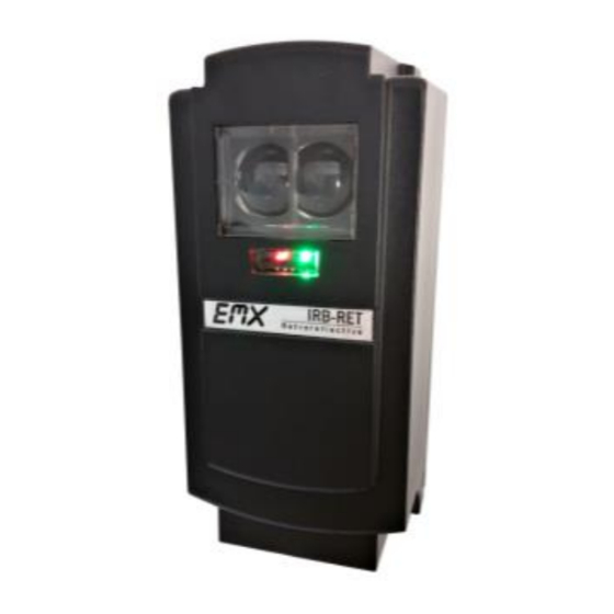
The IRB-RET retroreflective infrared photoeye is an external entrapment protection device type B1,
non-contact sensor for use with automatic gates and doors. Since the reflector directs the beam back to
the photoeye, wiring to the other side of the roadway is not needed. The IRB-RET operates up to 60 feet
over a wide range of voltages (6-40 VDC and 12-24 VAC). A red alignment indicator on the receiver
provides status information at a glance, making set-up and alignment easy. The IRB-RET provides
compatibility with most operators that accommodate monitored external entrapment devices per UL325.
Cautions and Warnings
This product is an accessory or part of a system. Install the IRB-RET according to instructions
from the gate or door operator manufacturer. Comply with all applicable codes and safety
regulations.
Retroreflective photoeyes rely on a reflective surface (a reflector) for proper operation.
In some cases, a vehicle with a reflective surface at a given distance can act as a reflector
and allow the gate to close on a vehicle.
Specifications
Operating Range
Power
Current (NC and 10K Monitoring Methods)
Current (Pulse Monitoring Methods)
Resistive Termination
Surge Protection
Relay Output Operation
Relay Output Configuration
Transmitter Power Cycle
Operating Temperature
Dimensions (L x W x H)
Environmental Rating
EMX Industries, Inc.
IRB-RET_Rev2.0_080619
IRB-RET
Universal Retroreflective Photoeye
Tech support: 216-834-0761
technical@emxinc.com
5 ft (1.5 m) to 60 ft (18.3 m)
6-40 VDC, 12-24 VAC
60 mA (relay activated)
ononly)
15 mA
10K ohm across NO contact (jumper selectable)
Thermal fuse
Light ON/Dark ON
Form C contacts (NO, COM, NC)
<300 mS (for use in NC and 10K monitoring)
-40° to 140°F (-40° to 60°C)
Methods)
3.1" (79 mm) x 2.7" (69 mm) x 6.6" (168 mm)
NEMA 4X
1/8
Advertisement
Table of Contents

Related Manuals for EMX IRB-RET


Summary of Contents for EMX IRB-RET
- Page 1 Since the reflector directs the beam back to the photoeye, wiring to the other side of the roadway is not needed. The IRB-RET operates up to 60 feet over a wide range of voltages (6-40 VDC and 12-24 VAC). A red alignment indicator on the receiver provides status information at a glance, making set-up and alignment easy.
-
Page 2: Ordering Information
0Hz failure over power supply lines Four-wire Pulse (2 Frequency): Provides 300Hz “heartbeat” unobstructed, 0Hz obstructed over • separate connection Four-wire Pulse (3 Frequency): Provides 300Hz “heartbeat” unobstructed, 2Hz obstructed, and • 0Hz failure over separate connection EMX Industries, Inc. Tech support: 216-834-0761 IRB-RET_Rev2.0_080619 technical@emxinc.com... -
Page 3: Installation
Determine the mounting location of the IRB-RET photoeye according to UL325 guidelines. • Deactivate the gate or door during photoeye installation. • The IRB-RET cannot be used for a detection range of less than 5 feet. • 1. Check the instruction manual of the gate or door operator to determine which monitoring method is necessary for that specific operator. - Page 4 8. The IRB-RET is housed in a NEMA 4X enclosure. To ensure the integrity of the enclosure, make sure the gasket is present, the cover is properly seated, and the cover screws are tight. The wiring to the enclosure must enter via a UL listed watertight fitting such as a strain relief or watertight conduit connector.
- Page 5 (Dark ON setting – normally open (NO) contact closes when the beam is unobstructed.) Pulse configurations require current limiting in the operator. The IRB-RET will pulse 300Hz when not • obstructed and 0Hz when obstructed.
- Page 6 Wiring Diagram A: Normally Closed Wiring Diagram B: 10K Resistive Termination* *If using the IRB-RET in an application that does not require UL325 monitoring across the Wiring Diagram C: Normally Closed normally open contact, it is possible to disable Power Cycle Transmitter Only the 10K resistor by moving the 10K jumper to pins 1 and 2.
- Page 7 Wiring Diagram D: Two-Wire Pulse Wiring Diagram D: Two-Wire Pulse (2 Frequency) (3 Frequency) Wiring Diagram E: Four-Wire Pulse Wiring Diagram E: Four-Wire Pulse (2 Frequency) (3 Frequency) EMX Industries, Inc. Tech support: 216-834-0761 IRB-RET_Rev2.0_080619 technical@emxinc.com...
-
Page 8: Troubleshooting
Warranty EMX Industries, Inc. products have a warranty against defects in materials and workmanship for a period of two years from date of sale to our customer. EMX Industries, Inc. Tech support: 216-834-0761 IRB-RET_Rev2.0_080619...
Need help?
Do you have a question about the IRB-RET and is the answer not in the manual?
Questions and answers