
Related Manuals for SeaLevel SeaLINK+2/PC.SC


Summary of Contents for SeaLevel SeaLINK+2/PC.SC
- Page 1 SeaLINK+2/PC.SC User Manual Item Number 2228 www.sealevel.com PO Box 830 – Liberty, SC 29657 864.843.4343...
-
Page 2: Table Of Contents
APPENDIX D – ASYNCHRONOUS COMMUNICATIONS..........24 APPENDIX E – CAD DRAWINGS – 2228 ................25 APPENDIX F - COMPLIANCE NOTICES ................26 ............26 EDERAL OMMUNICATIONS OMMISSION TATEMENT WARRANTY..........................27 © Sealevel Systems, Inc. SeaLINK+2/PC.SC User Manual SL9205 Revision 2/2009... -
Page 3: Introduction
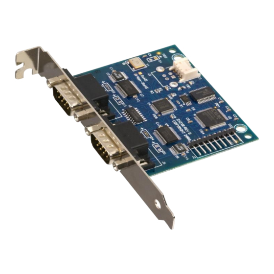
Introduction Sealevel’s SeaLINK® 2228 is a dual-port embedded USB to multi-interface serial adapter intended for mounting directly to a computer chassis, eliminating the need for an external converter and providing a clean, professional installation. All configuration and electrical interface selections are handled through the driver, so you never need to open the enclosure to set jumpers or switches. -
Page 4: Before You Get Started
Before You Get Started What’s Included The SeaLINK+2/PC.SC is shipped with the following items. If any of these items is missing or damaged please contact Sealevel for replacement. 2228 – USB to RS-232/422/485 Two Port Serial Interface Adapter CA260 – Internal USB Header Cable, 14” in Length Sealevel Software CD –... - Page 5 18 screw terminals to simplify field wiring of serial connections including RS-422 and RS-485 networks. The TB06 is designed to connect directly to Sealevel dual port DB9 serial cards or any cable with DB9M connectors. Adapters and Converters...
-
Page 6: Installation & Configuration
1. Start Windows. 2. Insert the Sealevel Software CD in to your CD drive. 3. If ‘Auto-Start’ is enabled, the installation window will automatically appear. Otherwise, navigate to the root directory of your CD drive and double-click the ‘autorun.exe’... - Page 7 9. When the ‘Ready to Install the Program’ window appears, click the ‘Install’ button to install the software onto the hard drive of your computer. The files will be automatically installed into the ‘C:\Program Files’ folder on your computer. © Sealevel Systems, Inc. - 5 - SeaLINK+2/PC.SC User Manual...
- Page 8 This declaration means that SeaCOM has not been certified by Microsoft’s testing labs. Note: All SeaCOM software and drivers have been fully tested by Sealevel. Clicking ‘Yes’ will not harm your system. 12. If SeaCOM has been previously installed on your computer, you do not need to install it again.
- Page 9 Linux Installation Refer to the subdirectory D:\Software\SeaCOM\Other\Linux\ (replace “D:” with your actual CD drive letter) found on the Sealevel Software CD. This folder contains valuable information on installing your serial adapter in the various Linux releases. Also included is a series of files explaining proper Linux syntax and typical Linux serial implementations.
-
Page 10: Hardware Installation
Windows installs USB serial devices. 1. A ‘Found New Hardware’ alert will appear above the system tray as shown below. 2. The ‘Found New Hardware Wizard’ will appear. © Sealevel Systems, Inc. - 8 - SeaLINK+2/PC.SC User Manual... - Page 11 Windows certification. Click on ‘Continue Anyway’. Note: All SeaCOM software and drivers have been fully tested by Sealevel. Clicking ‘Continue anyway’ will not harm your system. © Sealevel Systems, Inc.
- Page 12 6. The appropriate drivers for your SeaLINK device and version of Windows will be installed as shown. 7. Click ‘Finish’ to complete the installation of your hardware. 8. The ‘Found New Hardware Wizard’ appears a second time; repeat steps 4-8. © Sealevel Systems, Inc. - 10 - SeaLINK+2/PC.SC User Manual...
- Page 13 9. When the ‘Found New Hardware’ alert informs you that your hardware is installed and ready to use, you can proceed with verifying the installation to check functionality and/or locate the COM port assignments, if necessary. © Sealevel Systems, Inc. - 11 - SeaLINK+2/PC.SC User Manual...
-
Page 14: Verifying Installation
4. When Device Manager launches, look under ‘Ports (COM & LPT)’ to verify that the serial ports have been correctly installed. Note: Your system will assign the next available COM numbers which may vary for each computer used. © Sealevel Systems, Inc. - 12 - SeaLINK+2/PC.SC User Manual... -
Page 15: Hardware Configuration
The serial port properties menu will appear 3. Click on the ‘Interface Settings’ tab. Note: The Sealevel SeaCOM driver adds the ‘Interface Settings’ tab. If this tab is missing, SeaCOM is not correctly installed. 4. Select the appropriate electrical interface for your application and click on ‘OK’. - Page 16 485. By default, line termination is disabled, and this configuration can be set by placing a check next to ‘Enable Termination’ in the ‘RS-485 Advanced Configuration’ field, as shown in the image below. © Sealevel Systems, Inc. - 14 - SeaLINK+2/PC.SC User Manual...
- Page 17 Echo configuration is software selectable for half-duplex RS-485. By default, ECHO is disabled, and this configuration can be set by placing a check next to ‘Enable Echo’ in the ‘RS-485 Advanced Configuration’ field, as pictured below. © Sealevel Systems, Inc. - 15 - SeaLINK+2/PC.SC User Manual...
-
Page 18: Hardware Description
DB9M Serial Connectors The 2228 includes two DB9M serial connectors with full modem control signals implemented in RS-232 mode. Pin outs for these connectors are included in the following Electrical Specifications section. © Sealevel Systems, Inc. - 16 - SeaLINK+2/PC.SC User Manual... -
Page 19: Electrical Specifications
RS-422 & RS-485 Four-Wire (DB9 Male) Pin # Signal Note: Pins 6-9 are ‘no connect’ RS-485 Two-Wire (DB9 Male) Pin # Signal DATA- DATA+ Note: Pins 1, 2, 6-9 are ‘no connect’ © Sealevel Systems, Inc. - 17 - SeaLINK+2/PC.SC User Manual... -
Page 20: Technical Specifications
200mA necessary to power this device. Manufacturing All Sealevel Systems printed circuit boards are built to UL 94V0 rating and are 100% electrically tested. These printed circuit boards are solder mask over bare copper or solder mask over tin nickel. -
Page 21: Appendix A - Troubleshooting
Technical Support. 1. Ensure that the Sealevel Systems SeaCOM software has been installed on the machine so that the necessary files are in place to complete the installation. To confirm installation, click on the Windows ‘Start’... - Page 22 Click the ‘Settings’ button to open the COM Properties menu. Change your parameters to 9600 bits per second, 8 data bits, no parity, 1 stop bit, and no flow control, as pictured below. Click ‘Apply’ and ‘Ok’. © Sealevel Systems, Inc. - 20 - SeaLINK+2/PC.SC User Manual...
- Page 23 You can continue testing this port with different configurations or proceed with testing other ports, if necessary. If these steps do not solve your problem, please call Sealevel Systems’ Technical Support, (864) 843-4343. Our technical support is free and available from 8:00 AM to 5:00 PM Eastern Time Monday through Friday.
-
Page 24: Appendix B - How To Get Assistance
If possible, have your user manual and current adapter settings ready. The Sealevel website is an excellent resource. Our homepage is located online at http://www.sealevel.com. The most current software updates and user manuals are available via our homepage by clicking on the 'Drivers' or 'Manuals' links located under ‘Technical Support.’... -
Page 25: Appendix C - Electrical Interfaces
(Tx+ to Rx+ and Tx- to Rx-). Four-wire mode allows full duplex data transfers. RS-485 does not define a connector pinout or a set of modem control signals. RS-485 does not define a physical connector. © Sealevel Systems, Inc. - 23 - SeaLINK+2/PC.SC User Manual... -
Page 26: Appendix D - Asynchronous Communications
The communication parameters are baud rate, parity, number of data bits per character, and stop bits (i.e. 9600,N,8,1). © Sealevel Systems, Inc. - 24 - SeaLINK+2/PC.SC User Manual... -
Page 27: Appendix E - Cad Drawings - 2228
Appendix E – CAD Drawings – 2228 © Sealevel Systems, Inc. - 25 - SeaLINK+2/PC.SC User Manual... -
Page 28: Appendix F - Compliance Notices
Always use cabling provided with this product if possible. If no cable is provided or if an alternate cable is required, use high quality shielded cabling to maintain compliance with FCC/EMC directives. © Sealevel Systems, Inc. - 26 - SeaLINK+2/PC.SC User Manual... -
Page 29: Warranty
(RMA) number. The Customer agrees to insure the Product or assume the risk of loss or damage in transit, to prepay shipping charges to Sealevel, and to use the original shipping container or equivalent. Warranty is valid only for original purchaser and is not transferable.
Need help?
Do you have a question about the SeaLINK+2/PC.SC and is the answer not in the manual?
Questions and answers