
Related Manuals for Casio PCR-260B


Summary of Contents for Casio PCR-260B
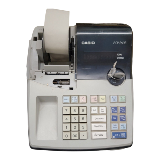
- Page 1 SERVICE MANUAL (without price) ELECTRONIC CASH REGISTER PCR-260B (EX-268EC) MAR. 2003 Printer Model : M-42V INDEX...
-
Page 2: Table Of Contents
CONTENTS PCR260B Page 1. SPECIFICATIONS..................1 2. INITIALIZE (MAC) OPERATION..............2 3. BLOCK DIAGRAM ..................3 3-1. PCB CONNECTION ..................... 3 3-2. BLOCK DIAGRAM ....................... 4 4. DISASSEMBLY .................... 5 5. CIRCUIT EXPLANATION ................8 5-1. Power supply circuit ....................8 5-2. -
Page 3: Specifications
1. SPECIFICATIONS 1-1. Electrical specifications 120V • Power consumption In operation Max. 0.11 A Min. 0.09 A Power OFF 0.06 A Mangan Battery (UM-3 × 3 pcs) • Memory protection Back-up battery 1 year (25 °C) Back-up period Battery life Replace the battery every 1 years. -
Page 4: Initialize (Mac) Operation
1-4. Drawer List DRAWER NAME Specification NOTE • DL-1325 (S type) D-14C2M-D54RP-9* 1-5. Option List DEVICE NAME MODEL NOTE • Wet cover WT-80 • INK ROLL IR-40 CAUTION Danger of explosion if battery is incorrectly replaced. Replace only with the same or equivalent type recommended by the manufacturer. -
Page 5: Block Diagram
3. BLOCK DIAGRAM 3-1. PCB CONNECTION — 3 —... -
Page 6: Block Diagram
3-2. BLOCK DIAGRAM Voltage detection Buzzer Reset IC Winder Motor drive circuit Printer drive circuit DISPLAY Drawer drive circuit KEYBOARD — 4 —... -
Page 7: Disassembly
4. DISASSEMBLY 1. Open the printer cover. 2. Remove the screw from the upper case. Remove the screw. 3. Slide the upper case towards front side. 4. Lift up the upper case. — 5 —... - Page 8 5. Open upper case by lifting it from the left side. 6. Remove all the cables on Main PCB and remove 3 screws. Remove 3 screws. Hook Hook Push the connector. Pull the wires. 7. Lift up the Main PCB to the right side to avoid the destruction of Display tube.
- Page 9 8. To remove the Printer unit, release the hook of point B, then lift up the Printer unit. Point B — 7 —...
-
Page 10: Circuit Explanation
5. CIRCUIT EXPLANATIONS 5-1. Power supply circuit DCS-267 RD4. 3EB2 1S2471 50V4. 7uF HE12TKYB 103K 10V100µ HE12TKYB103K 2SD1803(T) 1S2075K 1S2075K RD24EB2 WITH HEATSINK CRH100-FH11J-1R0 OSH-1625-MP Q1 2SD2396(K) TE-266-E2U 1SR35-100A X 4 RD3. 3EB2 DSTC50TKYR103K 470K E412181*1 2SC945 ECQ-B1H103-KF HE60TKYB222K FUSE 1A *B, *D, *G GNDP 1. -
Page 11: Reset Circuit
AC IN AC IN DISP1 µPD78042AGF C-11 B-10 C-21 C-22 C-15 C-23 C-16 C-17 C-18 B-14 C-19 C-20 E266-1 LBI268 B-15 Power ON 9.65 VAC 10.52V 5.76V 10.45V 0.78V 0.12V Pulse 5.07V -23.9V Plug out 4.13V 4.30V Voltage level is measured at the following condition. 1. -
Page 12: Printer Drive Circuit
5-3. Printer drive circuit Pin No.44 Pin No.45 Pin No.47 Pin No.62 Pin No.63 When the CPU starts printing, CPU sends MD signal to rotate motor unit. Then the printer sends back the RP(reset pulse),PT and PT (Timing pulse) to CPU. After CPU receives RP,PT andPT, CPU knows the position of printin wheel. - Page 13 Mode SW Mode SW AC cord Pin No. Signal In/Out Description Plug off 41 P32/TO2 Mode switch position (REG) 42 P31/TO1 Mode switch position (RF) 43 P30/TO0 Mode switch position (PRG) 44 P03/INTP3/CI0 In Reset pulse RP from printer 45 P02/INTP2 Pulse Sub timimg pulse Pt from printer 46 P01/INTP1...
-
Page 14: Diagnostic Operations
6 DIAGNOSTIC OPERATIONS 6-1. To start the diagnostic operation 1. Make MAC operation. 2. Turn the mode switch to PGM position. 3. Input "99999999" and press "SUB TOTAL" key. Note : Do not issue the receipt under REG / RF / X / Z mode before execute the diagnostic. If the machine issued a receipt, the diagnostic does not start. -
Page 15: Operations
6-3. Operations 1. Key code check (Hard key code) When pressing a key, the machine displays the following key code. Key code table FEED 029 Display 0 2 2 022 : Hard key code 2. Switch check Press " C " button, the switch condition is appered on a display. Always 0 No display No display... - Page 16 3. Individual test After finishing each test, the machine issues the following receipt. d1 # d1 : Test command No. Sample receipt 1234567890ST# 3-1. General test Press "1" key and "SUB TOTAL" key. The machine executes the following tests. All segment display Set time and date Date : 31st Dec.
- Page 17 3-3. Battery voltage check Press "7" key and "SUB TOTAL" key. Display the voltage level of memroy protection battery. To escape this test, turn the mode switch to "OFF". VCC=5.35V(Standard) 5 3 5 Voltage level 3-4. Print test Press "8" key and "SUB TOTAL" key. The machine prints all chatacter.
-
Page 18: Error Code List
7. ERROR CODE LIST 7-1. Operation error code Error codes appear on display whenever you make a mistake during operation. Error Code Meaning Action Changing modes without completing transaction. Return key to where is stops buzzing and press CA AMT TEND Printer paper is jammed. -
Page 19: Ic Data
8. IC DATA 8-1. LB1268 Equivalent circuit OUT1 OUT2 OUT3 6.8k 6.8k 8-2. S-80728AN-Z 1 OUT – Bottom view — 17 —... -
Page 20: Pcb Layout
9. PCB LAYOUT C N 8 A C I N A C I N G N D H O T C N 3 B - 2 B - 3 C - 2 B - 4 V F 2 D I S P 1 C - 3 D - 3 F - 2... -
Page 21: Circuit Diagram
10. CIRCUIT DIAGRAMS MODEL : PCR-260B (EX-268) CONTENTS 1. LOCATION OF PRINTED CIRCUIT BOARD ..............20 2. MAIN PCB CIRCUIT 2-1. MAIN PCB CIRCUIT (1/3) ..................21 2-2. MAIN PCB CIRCUIT (2/3) ..................22 2-3. MAIN PCB CIRCUIT (3/3) ..................23 3. - Page 22 Description: Board No. Drawing No.
- Page 23 Description: Board No. Drawing No.
- Page 24 Description: Board No. Drawing No.
- Page 25 HEATSINK Power Cord Description: Board No. Drawing No.
- Page 26 Description: Board No. Drawing No.
-
Page 27: Parts List
11. PARTS LIST MODEL : PCR-260B (EX-268EC) CONTENTS Exploded view ....................26 Main PCB block..................28 Button block ....................29 Power supply block ..................30 Upper case block ..................30 Printer block ....................30 Others ......................30 Cash drawer (DL-1325)................31 Printer Unit. -
Page 28: Exploded View
E266-1 Drawer — 26 —... - Page 29 Keyboard Block — 27 —...
-
Page 30: Main Pcb Block
I t e m Code No. Parts Name Specification Q ' t y Price code R a n k 1. Main PCB block 1011 1100 PCB ASSY /E268-1 E140376*14 3631 0330 FUSE 237001 2120 7393 IC/RESET S-80728AN-Z 1002 4618 UPD78044FGF177-3B9 2120 6253 IC/MOS LB1268... -
Page 31: Button Block
I t e m Code No. Parts Name Specification Q ' t y Price code R a n k 2. Button block 6221 3988 CAP/L E210964-1 6221 4025 CAP/S E311103-1 6245 7250 BUTTON/1 E311792-1 6245 7260 BUTTON/2 E311792-2 6245 7270 BUTTON/3 E311792-3 6245 7280... -
Page 32: Power Supply Block
I t e m Code No. Parts Name Specification Q ' t y Price code R a n k 3. Power supply block 3701 0228 CORD/POWER ME301S 3000 7098 TRANSFORMER TE-266-E2U 6246 2850 CASE/TRANSFORMER E311870-1 4. Upper case block 1011 1101 COVER/DISPLAY E140370-12 1009 3974... -
Page 33: Cash Drawer (Dl-1325)
7. Cash drawer (DL-1325) × 2 × 4 × 4 × 3 × 2 × 2 × 5 × 2 × 4 — 31 —... - Page 34 I t e m Code No. Parts Name Specification Q t y Price Code R a n k 1002 2673 DRAWER ASSY E240689*1 1002 2665 CASE/COIN E240644-1 6246 6571 PLATE /BILL HOLDER FIXING E311873-1 6248 1217 HOLDER/BILL E340725-1 6246 5220 SPRING/BILL HOLDER E412160-1 SCREW...
-
Page 35: Printer Unit. M-42V
8. Printer Unit. M-42V — 33 —... - Page 36 FOB Japan I t e m Code No. Parts Name Specification Q N . R . Y e n Unit Price 1903 0201 Rubber fitting F801001050 15 X 1908 7661 Motor F818051010 600 A 1908 7662 Motor gear F817051010 25 C 1908 7663 Cup screw M2x2.9 B040352118...
- Page 37 CASIO TECHNO CO.,LTD. Overseas Service Division 6-2, Hon-machi 1-Chome Shibuya-ku, Tokyo 151-8543, Japan...
Need help?
Do you have a question about the PCR-260B and is the answer not in the manual?
Questions and answers