Table of Contents

Subscribe to Our Youtube Channel
Related Manuals for IFM Ecomat 300 AC1355


Summary of Contents for IFM Ecomat 300 AC1355
- Page 1 Supplementary device manual AS-i controller e with Profibus DPV1 AC1355, AC1356 AC1365, AC1366 AS-i master profile: M4 Firmware: from version RTS 3.0 onwards Target: from V.15 onwards ® for CoDeSys from version 2.3 onwards...
- Page 2 As on: 14 Aug. 2008 © All rights reserved by ifm electronic gmbh. No part of this manual may be reproduced and used without consent. ifm electronic's...
-
Page 3: Table Of Contents
Contents On this manual ......................... 1-1 What do the symbols and formats stand for?..............1-1 What devices are described in this manual?..............1-2 How is this manual structured? ..................1-2 Overview: where is what? ..................... 1-3 Safety instructions ........................2-1 General.......................... - Page 4 Device-specific Profibus DP parameters..............7-25 7.4.1 Device-specific Profibus DP parameters (example)........7-25 7.4.2 Definitions in the GSD file................7-26 Finish set-up ........................ 7-27 DP module 7: Command channel ................... 8-1 List of commands in module 7..................8-1 Module 7, command 1: read master flags..............8-2 Module 7, command 2: change operating mode............
- Page 5 9.13 Module 12, extended command 10...20 (0A...14 ): force analogue data transfer directly to / from 3 AS-i slaves in each case ............... 9-20 9.14 Module 12, extended command 21 ): read ID character string of an AS-i slave with the profile 7.4 ..................9-25 9.15 Module 12, extended command 26 ): read AS-i master version....
- Page 6 Acyclic services for Profibus DPV1 ..................10-1 10.1 Description........................10-1 10.2 Services for acyclic data transfer between DPM1 master and slave ......10-2 10.3 Services for acyclic data transfer between DPM2 master and slave ......10-2 10.4 DPV1 addresses in slot 0 for access via PLC............. 10-3 10.5 Examples........................
- Page 7 11.20 DPV1 command 38 ): acyclic manufacturer-specific read call of an AS-i slave with CTT2 profile (S-7.5.5, S-7.A.5 or S-B.A.5) ......11-45 11.21 DPV1 command 39 ): acyclic manufacturer-specific write call of an AS-i slave with CTTS profile (S-7.5.5, S-7.A.5 or S-B.A.5)......11-49 11.22 DPV1 command 50 ): read current configuration of AS-i slaves 0(A)...15(A).....................
- Page 8 Terms, abbreviations ......................15-1 Index ............................16-1...
-
Page 9: On This Manual
On this manual What do the symbols and formats stand for? On this manual In this chapter you will find an overview of the following points: • What do the symbols and formats stand for? • What devices are described in this manual? •... -
Page 10: What Devices Are Described In This Manual?
"CoDeSys for Automation Alliance" is given. This manual can be downloaded free of charge from ifm's website at: → www.ifm.com> Select country/language > [Service] > [Download] > [Bus system AS-interface] Description of the Ethernet programming interface → Separate supplement to this device manual. -
Page 11: Overview: Where Is What?
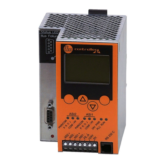
On this manual Overview: where is what? Overview: where is what? metal housing IP20 key to unlock the device from a rail status LEDs of the fieldbus interface text/graphics display (option) 4 pushbuttons option: fieldbus interface (here: Ethernet) status LEDs terminals for the voltage supply Option: 6-pole RJ11 socket of RS-232C... - Page 12 On this manual Overview: where is what?
-
Page 13: Safety Instructions
Property damage or bodily injury possible when the notes in this manual are not adhered to! assumes no liability for this. ifm electronic ► The acting person must have read and understood the safety instructions and the corresponding chapters of this manual before performing any work on or with this device. - Page 14 Safety instructions Functions and features...
-
Page 15: System Requirements
System requirements Information concerning the device System requirements Information concerning the device → separate basic instructions of the device manual Information concerning the software → separate basic instructions of the device manual Required accessories Basic functions → separate basic instructions of the device manual For configuration and programming you also need: •... - Page 16 System requirements Required accessories...
-
Page 17: Getting Started
Getting started Connection Getting started Connection ► Connect the functional earth ► Connect the yellow AS-i cable for every master ► Connect the 24 V supply ► Connect the Profibus cable to the fieldbus master Set up the AS-i master ►... - Page 18 Getting started Set up Profibus DPV1...
-
Page 19: Function
Function Data management Function Basic functions → separate basic instructions of the device manual Ethernet programming interface → separate complementary device manual Data management The controller e consists of different units: text/graphics display AS-i master 1 fieldbus interface Profibus DPV1 AS-i master 2 (optional) Ethernet programming interface... -
Page 20: Status Led For The Fieldbus
Function Status LED for the fieldbus Status LED for the fieldbus For Profibus DP there is only one red LED [Bus Failure]. Description When response monitoring (watchdog) active: ● lights no Profibus connection When response monitoring (watchdog) active: Profibus connection ok ○... -
Page 21: Menu
Menu Main menu [Quick Setup] Menu NOTE In this manual the menu texts are all in English. Basic functions → separate basic instructions of the device manual Main menu [Quick Setup] Quick setting of the AS-i and fieldbus parameters, reading of the parameter data (password level 1 required). -
Page 22: Main Menu [Fieldbus Setup]
Menu Main menu [Fieldbus Setup] Menu tree Explanation • Analogue outputs in the fieldbus master on AS-i master 2 • Fieldbus data diagnosis • Fieldbus master command channel • Digital inputs in the fieldbus master of single or A slaves on AS-i master 1 (cycle starts again) ►... - Page 23 Menu Main menu [Fieldbus Setup] Menu tree Explanation • Analogue outputs in the fieldbus master on AS-i master 1 • Analogue inputs in the fieldbus master on AS-i master 2 • Analogue outputs in the fieldbus master on AS-i master 2 •...
- Page 24 Menu Main menu [Fieldbus Setup]...
-
Page 25: Set-Up
Set-up Parameter setting of the controllere Set-up This chapter shows you how to get the Profibus interface started quickly. Parameter setting of the controller e 7.1.1 Parameter setting of slaves in the controller e Set the parameters of the slaves in the AS-i controller e as described in the basic device manual. 7.1.2 Set the parameters of the fieldbus interface in the controller e [Menu] >... -
Page 26: Description
Set-up Connect the controllere to the Profibus host Fieldbus Address ► Scroll to the requested address with [▲] / [▼]. ▲ ▼ Fieldbus Address ► Save the fieldbus address with [OK]. ▲ ▼ Fieldbus Baudrate > If there is communication with the fieldbus master: #### KBaud display of negotiated baud rate ►... - Page 27 Set-up Parameter setting of the Profibus host Programming software The data of the controller e or the connected AS-i systems to be transferred can be defined (by indicating the length of up to 12 modules) in the programming software for the Profibus DP master system (host).
-
Page 28: Assigning The Addresses Of The Inputs/Outputs To The Host "Locations"
Set-up Parameter setting of the Profibus host 7.3.1 Assigning the addresses of the inputs/outputs to the host "locations" For Profibus DP, virtual locations in the host are assigned to the inputs/outputs addressed via AS-i. NOTE Addressing of CTT2 and CTT3 slaves → separate basic instructions of the device manual and there →... - Page 29 Set-up Parameter setting of the Profibus host Digital inputs and outputs of the slaves at start address 0 Start address Bits 7...4 Bits 3...0 (Slave 0) reserved for master flags Slave 1 Reserve Conf. No Slave PF.Err Err. 0 .7 0 .6 0 .5 0 .4...
- Page 30 Set-up Parameter setting of the Profibus host example: Siemens S7 with AS-i controller e as gateway. The digital inputs/outputs on the AS-i controller e are assigned to the host as bytes 65...80. In this constellation, how are the IEC addresses distributed to the inputs and outputs of the slaves? → next page...
- Page 31 Set-up Parameter setting of the Profibus host Digital inputs and outputs of the slaves at start address 65 Start address Bits 7...4 Bits 3...0 (Slave 0) reserved for master flags Slave 1 Conf. Reserve NoSlave PF.Err Err. 65 .7 65 .6 65 .5 65 .4 65 .3...
- Page 32 Set-up Parameter setting of the Profibus host Analogue inputs/outputs 1st example: Siemens S7 with AS-i controller e as gateway. The analogue inputs on the AS-i controller e are assigned to the host as bytes 256...287 (32 bytes = 16 words). The analogue outputs on the AS-i controller e are assigned to the host as bytes 256...271 (16 bytes = 8 words).
- Page 33 Set-up Parameter setting of the Profibus host In this constellation, how are the IEC addresses distributed to the inputs and outputs of the slaves? The following tables show the correlation between start address and AS-i slave address (preset parameters): Analogue inputs Start address [bytes] Slave address* Channel number...
- Page 34 Set-up Parameter setting of the Profibus host Analogue inputs and outputs of the slaves at start address ### SORRY - i n w o r k - SORRY 7-10...
-
Page 35: Assign Plc Addresses To The Profibus Modules
Set-up Parameter setting of the Profibus host 7.3.2 Assign PLC addresses to the Profibus modules What are "Profibus modules"? These are entries in a parameter setting database of the programming software for the Profibus DP master system (host). There you assign the individual "modules" to the virtual "locations". - Page 36 Set-up Parameter setting of the Profibus host IEC address area Data flow Description DP module AS-i host from master 1, slaves 1B...31B, %QB11.1 %QB11.31 → – digital outputs master 2, slaves 1B...31B, %QIB12.1 %QB12.31 → – digital outputs master 1, slaves 1...31, %QW21.1.x %QW21.31.x →...
-
Page 37: Define Profibus Dp Modules
Set-up Parameter setting of the Profibus host 7.3.3 Define Profibus DP modules The text of the different options of the modules always starts with the module number ( → photo page 7-3, section Programming software). So all options in the module list of the hardware catalogue starting with "1:"... - Page 38 Set-up Parameter setting of the Profibus host Module 1: Binary inputs/outputs of single / A slaves of AS-i master 1 Contents Binary inputs and outputs of single or A slaves of AS-i master 1 Length 0...16 bytes I/O (if not used: length = 0) Byte no.
- Page 39 Set-up Parameter setting of the Profibus host Module 2: Binary inputs/outputs of single / A slaves of AS-i master 2 Contents Binary inputs and outputs of single or A slaves of AS-i master 2 Length 0...16 bytes I/O (if not used: length = 0) Byte no.
- Page 40 Set-up Parameter setting of the Profibus host Module 3: Binary inputs/outputs of B slaves of AS-i master 1 Contents Binary inputs and outputs of B slaves of the AS-i master 1 Length 0...16 bytes I/O (if not used: length = 0) Byte no.
- Page 41 Set-up Parameter setting of the Profibus host Module 4: Binary inputs/outputs of B slaves of AS-i master 2 Contents Binary inputs and outputs of B slaves of AS-i master 2 Length 0...16 bytes I/O (if not used: length = 0) Byte no.
- Page 42 Set-up Parameter setting of the Profibus host Module 5: Analogue inputs of AS-i master Contents Multiplexed analogue inputs of AS-i master 1 and 2 Length 2-word consistent I/O ( if not used: length = 0) DP master request (only 1 word) Bit: Word SSSSS...
- Page 43 Set-up Parameter setting of the Profibus host Module 6: Analogue outputs of AS-i master Contents Multiplexed analogue outputs of AS-i master 1 and 2 Length 2-word consistent I/O (if not used: length = 0) NOTE If analogue outputs are also triggered in module 11, the value written in module 6 is overwritten with the data of module 11.
- Page 44 Set-up Parameter setting of the Profibus host Module 7: Command channel Contents Command channel → page 8-1, chapter DP module 7: Command channel Length 4-byte consistent I/O (if not used: length = 0) IMPORTANT: For the query read only the required bytes. Unused bytes can contain information of previous queries.
- Page 45 Set-up Parameter setting of the Profibus host The commands are only executed if the command number (the first byte) changes. If the same command is to be executed with different data several times (e.g. read slave lists), the operating mode "continuous command"...
- Page 46 Set-up Parameter setting of the Profibus host Description Byte 2 Byte 3 Byte 4 ► change current slave parameters – parameters MMXSSSSS reflected > response: – MMXSSSSS parameters reserved – – – 17, 18 ► config all – – MM000000 >...
- Page 47 Set-up Parameter setting of the Profibus host Module 8: data transfer between Profibus DP master and PLC in the controller e Contents Field for the data transfer between the Profibus DP master system and the PLC functions in the controller e Length 0...64-word inputs (if not used: length = 0) Module 9: data transfer between PLC in the controller e and Profibus DP master...
- Page 48 Set-up Parameter setting of the Profibus host Module 12: Extended command channel Contents Extended command channel Length 2...18-word consistent inputs/outputs (if not used: length = 0) NOTE In some controllers larger consistent data fields cannot be processed in the direct I/O address area; special function calls are then required.
-
Page 49: Device-Specific Profibus Dp Parameters
Set-up Device-specific Profibus DP parameters Device-specific Profibus DP parameters With up to 100 bytes of the device-specific Profibus parameters the addresses of the analogue input slaves and analogue output slaves to be transferred in parallel can be defined and the parameters of the connected AS-i slaves can be set. -
Page 50: Examples
Set-up Device-specific Profibus DP parameters 7.4.2 Definitions in the GSD file The definitions in the GSD file (GSD = General Station Description) enable easy access to the device parameters if this is supported by the configuration tool of the Profibus DP master: Example Siemens Step 7 Byte 37... -
Page 51: Finish Set-Up
Set-up Finish set-up For "Disabled" (default) the controller e only transmits the standard diagnosis. An AS-i error state has no direct effect on the Profibus DP but must then be monitored otherwise by the PLC (using the bits 4..7 in the first byte or via the command channel). Byte 37 Bit 4 = TRUE Finish set-up... - Page 52 Set-up Finish set-up 7-28...
-
Page 53: List Of Commands In Module 7
DP module 7: Command channel List of commands in module 7 DP module 7: Command channel → page 7-21, table Overview of the commands in the DP module 7 List of commands in module 7 Command number → page Description Hexa- decimal decimal... -
Page 54: Module 7, Command 1: Read Master Flags
DP module 7: Command channel Module 7, command 1: read master flags Module 7, command 1: read master flags Structure Request of DP master Byte MM = master no. (1…2) not used not used Response from controller e Byte D6 = command code D7 = error code →... -
Page 55: Module 7, Command 2: Change Operating Mode
DP module 7: Command channel Module 7, command 2: change operating mode Module 7, command 2: change operating mode Request of DP master Byte MM = master no. (1…2) 0 = protected mode not used 1 = configuration mode not used *) Response from controller e Byte D6 = command code... -
Page 56: Module 7, Command 3: Read Current Slave Configuration
DP module 7: Command channel Module 7, command 3: read current slave configuration Module 7, command 3: read current slave configuration Structure Request of DP master MM = master no. (1…2) X = slave type (0…1) Byte 0 = standard / A slave 1 = B slave SSSSS SSSSS = slave no. -
Page 57: Module 7, Command 4: Read Projected Slave Configuration
DP module 7: Command channel Module 7, command 4: read projected slave configuration Module 7, command 4: read projected slave configuration Structure Request of DP master MM = master no. (1…2) X = slave type (0…1) Byte 0 = standard / A slave 1 = B slave SSSSS SSSSS = slave no. -
Page 58: Module 7, Command 5: Change Projected Slave Configuration
DP module 7: Command channel Module 7, command 5: change projected slave configuration Module 7, command 5: change projected slave configuration Structure Request of DP master MM = master no. (1…2) X = slave type (0…1) Byte 0 = standard / A slave 1 = B slave SSSSS SSSSS = slave no. -
Page 59: Module 7, Command 6: Read Slave Parameter
DP module 7: Command channel Module 7, command 6: read slave parameter Module 7, command 6: read slave parameter Structure Request of DP master MM = master no. (1…2) X = slave type (0…1) Byte 0 = standard / A slave 1 = B slave SSSSS SSSSS = slave no. -
Page 60: Module 7, Command 7: Change Projected Slave Parameters
DP module 7: Command channel Module 7, command 7: change projected slave parameters Module 7, command 7: change projected slave parameters NOTE The projected parameters can only be changed if the AS-i master operates in the configuration mode. Activation → page Structure Request of DP master MM = master no. -
Page 61: Module 7, Command 8: Read Las (List Of Active Slaves)
DP module 7: Command channel Module 7, command 8: read LAS (list of active slaves) Module 7, command 8: read LAS (list of active slaves) Slave group The 2 feedback bytes can only give information about max. 16 slaves. Therefore the slaves are divided in 4 groups (→... - Page 62 DP module 7: Command channel Module 7, command 8: read LAS (list of active slaves) Example: Read LAS (list of active slaves) of slave group 1 on master 1 Request of DP master Byte no. Value [hex] Description 08 = command 8 (slave no.
-
Page 63: Module 7, Command 9: Read Lds (List Of Detected Slaves)
DP module 7: Command channel Module 7, command 9: read LDS (list of detected slaves) 8.10 Module 7, command 9: read LDS (list of detected slaves) The 2 feedback bytes can only give information about max. 16 slaves. Therefore the slaves are divided into 4 groups (→... -
Page 64: Read Lpf (List Of Slaves With Periphery Fault)
DP module 7: Command channel Module 7, command 10dec (0Ahex): read LPF (list of slaves with periphery fault) 8.11 Module 7, command 10 read LPF (list of slaves with periphery fault) The 2 feedback bytes can only give information about max. 16 slaves. Therefore the slaves are divided into 4 groups (→... -
Page 65: Read Lps (List Of Projected Slaves)
DP module 7: Command channel Module 7, command 11dec (0Bhex): read LPS (list of projected slaves) 8.12 Module 7, command 11 read LPS (list of projected slaves) The 2 feedback bytes can only give information about max. 16 slaves. Therefore the slaves are divided into 4 groups (→... -
Page 66: Read Telegram Error Counter
DP module 7: Command channel Module 7, command 13dec (0Dhex): read telegram error counter 8.13 Module 7, command 13 read telegram error counter Structure Request of DP master MM = master no. (1…2) X = slave type (0…1) Byte 0 = standard / A slave 1 = B slave SSSSS SSSSS = slave no. -
Page 67: Read Configuration Error Counter
DP module 7: Command channel Module 7, command 14dec (0Ehex): read configuration error counter 8.14 Module 7, command 14 read configuration error counter Structure Request of DP master MM = master no. (1…2) Byte not used *) not used *) Response from controller e Byte D6 = command code... -
Page 68: Read As-I Cycle Counter
DP module 7: Command channel Module 7, command 15dec (0Fhex): read AS-i cycle counter 8.15 Module 7, command 15 read AS-i cycle counter Structure Request of DP master MM = master no. (1…2) Byte not used *) not used *) Response from controller e Byte D6 = command code... -
Page 69: Change Current Slave Parameters
DP module 7: Command channel Module 7, command 16dec (10hex): change current slave parameters 8.16 Module 7, command 16 change current slave parameters Structure Request of DP master MM = master no. (1…2) X = slave type (0…1) Byte 0 = standard / A slave 1 = B slave SSSSS SSSSS = slave no. -
Page 70: Config. All
DP module 7: Command channel Module 7, command 19dec (13hex): config. all 8.17 Module 7, command 19 config. all Structure Request of DP master MM = master no. (1…2) Byte not used *) not used *) Response from controller e Byte D6 = command code D7 = error code... -
Page 71: Save Configuration In Flash
DP module 7: Command channel Module 7, command 21dec (15hex): save configuration in flash 8.18 Module 7, command 21 save configuration in flash Structure Request of DP master MM = master no. (1…2) Byte not used *) not used *) Response from controller e Byte D6 = command code... -
Page 72: Reset Telegram Error Counter Of A Slave
DP module 7: Command channel Module 7, command 22dec (16hex): reset telegram error counter of a slave 8.19 Module 7, command 22 reset telegram error counter of a slave Structure Request of DP master MM = master no. (1…2) X = slave type (0…1) Byte 0 = standard / A slave 1 = B slave... -
Page 73: Address Slave
DP module 7: Command channel Module 7, command 23dec (17hex): address slave 8.20 Module 7, command 23 address slave IMPORTANT: The controller e must be in the configuration mode. Structure Request of DP master MM = master no. (1…2) X = slave type (0…1) Byte 0 = standard / A slave 1 = B slave... -
Page 74: Operating Mode "Continuous Command"
DP module 7: Command channel Module 7, command 62dec (3Ehex): operating mode "continuous command“ 8.21 Module 7, command 62 operating mode "continuous command“ If the "continuous" mode is active, the current command is transferred in every cycle. NOTE The continuous mode influences the behaviour of the controller e . The mode should only be used for read commands. -
Page 75: No Operation Command Without Function
DP module 7: Command channel Module 7, command 63dec (3Fhex): no operation command without function 8.22 Module 7, command 63 no operation command without function Structure Request of DP master Byte not used *) not used *) not used *) Response from controller e D6 = command code Byte... - Page 76 DP module 7: Command channel Module 7, command 63dec (3Fhex): no operation command without function 8-24...
-
Page 77: List Of Extended Commands In Module 12
DP module 12: Extended command channel List of extended commands in module 12 DP module 12: Extended command channel The extended command channel serves for exchange of data between the AS-i controller e and the Profibus host (PLC). NOTE In some controllers larger consistent data fields cannot be processed in the direct I/O address area. Then, special function calls are required. - Page 78 DP module 12: Extended command channel List of extended commands in module 12 Command number → page Description hexa- decimal decimal read projected configuration of slaves 1(A)...15(A) 9-63 read projected configuration of slaves 16(A)...31(A) 9-64 read projected configuration of slaves 1B...15B 9-65 read projected configuration of slaves 16B...31B 9-66...
-
Page 79: Data Structure
DP module 12: Extended command channel Data structure Data structure Length: 2...18-word consistent inputs/outputs (if not used: length = 0) The word 2 is reserved for 7.4 commands (if not used: word = 0). Request of DP master Word user ID command number slave address length... - Page 80 DP module 12: Extended command channel Data structure User ID NOTE If a command is to be executed, the user ID must be changed! Changing the command number does not start the execution. If a command is to be executed several times, the user ID must be changed accordingly, e.g. by counting up.
-
Page 81: Error Codes In The Module 12
DP module 12: Extended command channel Error codes in the module 12 Error codes in the module 12 Value [hex] Description no slave response or: master is in the offline mode when calling the command no slave with the old address found slave with address 0 connected no slave with the new address found error when deleting the old address... -
Page 82: Module 12, Extended Command 0: No Execution Of A Command
DP module 12: Extended command channel Module 12, extended command 0: no execution of a command Module 12, extended command 0: no execution of a command Request of DP master Word no. Value [hex] Description 08 = user ID changes e.g. to 8 0800 00 = command number 0 2…18... -
Page 83: Module 12, Extended Command 1: Write Parameters To A Connected As-I Slave
DP module 12: Extended command channel Module 12, extended command 1: write parameters to a connected AS-i slave Module 12, extended command 1: write parameters to a connected AS-i slave Request of DP master Word user ID command number = 01 reserved = 0 reserved = 0 slave address... - Page 84 DP module 12: Extended command channel Module 12, extended command 1: write parameters to a connected AS-i slave Response from controller e (gateway) in case of an error Word E=1 B=0 reflected user ID reflected command number = 01 reserved = 0 reserved = 0 Error code ignored...
-
Page 85: Module 12, Extended Command 3: Adopt And Store Connected As-I Slaves In The Configuration
DP module 12: Extended command channel Module 12, extended command 3: adopt and store connected AS-i slaves in the configuration Module 12, extended command 3: adopt and store connected AS-i slaves in the configuration Request of DP master Word user ID command number = 03 = 03 not used... -
Page 86: Module 12, Extended Command 34
DP module 12: Extended command channel Module 12, extended command 3: adopt and store connected AS-i slaves in the configuration Response from controller e (gateway) in case of an error Word E=1 B=0 reflected user ID reflected command number = 03 reserved = 0 error code Legend →... -
Page 87: Module 12, Extended Command 4: Write Lps
DP module 12: Extended command channel Module 12, extended command 4: write LPS Module 12, extended command 4: write LPS Request of DP master Word user ID command number = 04 = 04 reserved = 0 15(A) 14(A) 13(A) 12(A) 11(A) 10(A) 9(A) - Page 88 DP module 12: Extended command channel Module 12, extended command 4: write LPS Response from controller e (gateway) in the normal case Word E=0 B=0 reflected user ID reflected command number = 04 not changed 2…18 Legend → page Example: Word no.
-
Page 89: Module 12, Extended Command 5: Set The Operating Mode Of The As-I Master
DP module 12: Extended command channel Module 12, extended command 5: set the operating mode of the AS-i master Module 12, extended command 5: set the operating mode of the AS-i master Request of DP master Word user ID command number = 05 = 05 reserved = 0 reserved = 0... -
Page 90: Module 12, Extended Command 51
DP module 12: Extended command channel Module 12, extended command 5: set the operating mode of the AS-i master Response from controller e (gateway) in case of an error Word E=1 B=0 reflected user ID reflected command number = 05 reserved = 0 reserved = 0 error code... -
Page 91: Module 12, Extended Command 6: Readdress A Connected As-I Slave
DP module 12: Extended command channel Module 12, extended command 6: readdress a connected AS-i slave 9.10 Module 12, extended command 6: readdress a connected AS-i slave Request of DP master Word user ID Command number = 06 = 06 reserved = 0 reserved = 0 old slave address... - Page 92 DP module 12: Extended command channel Module 12, extended command 6: readdress a connected AS-i slave Response from controller e (gateway) in case of an error Word E=1 B=0 reflected user ID reflected command number = 06 reserved = 0 reserved = 0 error code ignored...
-
Page 93: Module 12, Extended Command 7: Set The Auto Address Mode Of The As-I Master
DP module 12: Extended command channel Module 12, extended command 7: set the auto address mode of the AS-i master 9.11 Module 12, extended command 7: set the auto address mode of the AS-i master Request of DP master Word user ID command number = 07 = 07... -
Page 94: Module 12, Extended Command 9: Change Extended Id Code 1 In The As-I Slave
DP module 12: Extended command channel Module 12, extended command 9: change extended ID code 1 in the AS-i slave 9.12 Module 12, extended command 9: change extended ID code 1 in the AS-i slave Request of DP master Word user ID command number = 09 = 09... -
Page 95: Module 12, Extended Command 97
DP module 12: Extended command channel Module 12, extended command 9: change extended ID code 1 in the AS-i slave Response from controller e (gateway) in case of an error Word E=1 B=0 reflected user ID reflected command number = 09 reserved = 0 reserved = 0 error code... -
Page 96: Directly To / From 3 As-I Slaves In Each Case
DP module 12: Extended command channel Module 12, extended command 10...20dec (0A...14hex): force analogue data transfer directly to / from 3 AS-i slaves in each case 9.13 Module 12, extended command 10...20 (0A...14 force analogue data transfer directly to / from 3 AS-i slaves in each case Request of DP master Word... -
Page 97: Module 12, Extended Command 105
DP module 12: Extended command channel Module 12, extended command 10...20dec (0A...14hex): force analogue data transfer directly to / from 3 AS-i slaves in each case Example request of DP master: Word no. Value [hex] Description M=0: AS-i master 1 090A 09 = user ID changes e.g. - Page 98 DP module 12: Extended command channel Module 12, extended command 10...20dec (0A...14hex): force analogue data transfer directly to / from 3 AS-i slaves in each case Response from controller e (gateway) Word E=0 B=0 reflected user ID reflected command number = 0A…14 input data or reflected output data AS-i slave 1(A), channel 0 input data or reflected output data AS-i slave 1(A), channel 1 input data or reflected output data AS-i slave 1, channel 2 or...
- Page 99 DP module 12: Extended command channel Module 12, extended command 10...20dec (0A...14hex): force analogue data transfer directly to / from 3 AS-i slaves in each case from master profile M4 onwards: TIA ¹) TIx=0: slave sends input data as value (15-bit length, with sign) TIx=1: slave sends input data as bit pattern (16-bit length, without sign) TIB ²) TOA ¹)
- Page 100 DP module 12: Extended command channel Module 12, extended command 10...20dec (0A...14hex): force analogue data transfer directly to / from 3 AS-i slaves in each case Assignment command numbers 10...20 ←→slave addresses Command number Slaves Hexa- Decimal decimal – – 9-24...
-
Page 101: As-I Slave With The Profile 7.4
DP module 12: Extended command channel Module 12, extended command 21dec (15hex): read ID character string of an AS-i slave with the profile 7.4 9.14 Module 12, extended command 21 read ID character string of an AS-i slave with the profile 7.4 Request of DP master Word user ID... - Page 102 DP module 12: Extended command channel Module 12, extended command 21dec (15hex): read ID character string of an AS-i slave with the profile 7.4 Mux field number of multiplexed data words length: 3 bits permitted values: 0…3 number = Mux field + 1 E type characterises the slave concerning functionality and data structure length: 5 bits...
- Page 103 DP module 12: Extended command channel Module 12, extended command 21dec (15hex): read ID character string of an AS-i slave with the profile 7.4 Response from controller e (gateway) in case of an error Word E=1 B=0 reflected user ID reflected command number = 15 reserved = 0 reserved = 0...
- Page 104 DP module 12: Extended command channel Module 12, extended command 26dec (1Ahex): read AS-i master version 9.15 Module 12, extended command 26 read AS-i master version Request of DP master Word no. Value [hex] Description M=0: AS-i master 1 131A 13 = user ID changes e.g.
- Page 105 DP module 12: Extended command channel Module 12, extended command 28dec (1Chex): deactivate the slave reset when changing to the protected mode 9.16 Module 12, extended command 28 deactivate the slave reset when changing to the protected mode Request of DP master Word user ID command number = 1C...
- Page 106 DP module 12: Extended command channel Module 12, extended command 31dec (1Fhex): one-time execution of the "Extended safety monitor protocol" in the "Safety at work" monitor 9.17 Module 12, extended command 31 one-time execution of the "Extended safety monitor protocol" in the "Safety at work"...
- Page 107 DP module 12: Extended command channel Module 12, extended command 31dec (1Fhex): one-time execution of the "Extended safety monitor protocol" in the "Safety at work" monitor Response from controller e (gateway) in the normal case Word B=0 M=0 reflected user ID reflected command number = 1F reserved = 0 reserved = 0...
- Page 108 DP module 12: Extended command channel Module 12, extended command 31dec (1Fhex): one-time execution of the "Extended safety monitor protocol" in the "Safety at work" monitor Description of the different fields: Word no. 4: LEDs OSSD 1 LEDs OSSD 2 Description green: contacts of the output circuits closed yellow: start-up / restart disable active...
- Page 109 DP module 12: Extended command channel Module 12, extended command 31dec (1Fhex): one-time execution of the "Extended safety monitor protocol" in the "Safety at work" monitor 1st to 6th colour output circuit 1/2: Description green, continuous green, flashing yellow, continuous yellow, flashing red, continuous red, flashing...
- Page 110 DP module 12: Extended command channel Module 12, extended command 31dec (1Fhex): one-time execution of the "Extended safety monitor protocol" in the "Safety at work" monitor Response from controller e (gateway) in case of an error Word B=0 M=0 reflected user ID reflected command number = 1F reserved = 0 reserved = 0...
-
Page 111: Of An As-I Slave With The Profile S-7.4
DP module 12: Extended command channel Module 12, extended command 33dec (21hex): read the diagnostic character string of an AS-i slave with the profile S-7.4 9.18 Module 12, extended command 33 read the diagnostic character string of an AS-i slave with the profile S- Request of DP master Word user ID... - Page 112 DP module 12: Extended command channel Module 12, extended command 33dec (21hex): read the diagnostic character string of an AS-i slave with the profile S-7.4 Response from controller e (gateway) Word reflected user ID reflected command number = 21 slave address number of bytes to be received diagnostic character string 1 diagnostic character string 0...
-
Page 113: Of An As-I Slave With The Profile S-7.4
DP module 12: Extended command channel Module 12, extended command 34dec (22hex): read parameter character string of an AS-i slave with the profile S-7.4 9.19 Module 12, extended command 34 read parameter character string of an AS-i slave with the profile S-7.4 Request of DP master Word user ID... -
Page 114: Of An As-I Slave With The Profile S-7.4
DP module 12: Extended command channel Module 12, extended command 35dec (23hex): write parameter character string of an AS-i slave with the profile S-7.4 9.20 Module 12, extended command 35 write parameter character string of an AS-i slave with the profile S-7.4 Request of DP master Word user ID... - Page 115 DP module 12: Extended command channel Module 12, extended command 35dec (23hex): write parameter character string of an AS-i slave with the profile S-7.4 Response from controller e (gateway) Word reflected user ID reflected command number = 23 slave address number of bytes to be sent not changed 3…18...
- Page 116 DP module 12: Extended command channel Module 12, acyclic command 36 dec (24hex): standard read call of an AS-i slave with CTT2 profile (S-7.5.5, S-7.A.5 or S-B.A.5) 9.21 Module 12, acyclic command 36 standard read call of an AS-i slave with CTT2 profile (S-7.5.5, S-7.A.5 or S-B.A.5) –...
- Page 117 DP module 12: Extended command channel Module 12, acyclic command 36 dec (24hex): standard read call of an AS-i slave with CTT2 profile (S-7.5.5, S-7.A.5 or S-B.A.5) Response from controller e (gateway) in the normal case Word reflected user ID reflected command number = 24 TG L32 slave address...
- Page 118 DP module 12: Extended command channel Module 12, acyclic command 36 dec (24hex): standard read call of an AS-i slave with CTT2 profile (S-7.5.5, S-7.A.5 or S-B.A.5) Response from controller e (gateway) in case of an error (error detected by AS-i master) Word E=1 B=0 reflected user ID...
- Page 119 DP module 12: Extended command channel Module 12, acyclic command 36 dec (24hex): standard read call of an AS-i slave with CTT2 profile (S-7.5.5, S-7.A.5 or S-B.A.5) Response from controller e (gateway) in case of an error (error detected by AS-i slave) Word reflected user ID reflected command number = 24...
- Page 120 DP module 12: Extended command channel Module 12, acyclic command 37dec (25hex): standard write call of an AS-i slave with CTT2 profile (S-7.5.5, S-7.A.5 or S-B.A.5) 9.22 Module 12, acyclic command 37 standard write call of an AS-i slave with CTT2 profile (S-7.5.5, S-7.A.5 or S-B.A.5) –...
- Page 121 DP module 12: Extended command channel Module 12, acyclic command 37dec (25hex): standard write call of an AS-i slave with CTT2 profile (S-7.5.5, S-7.A.5 or S-B.A.5) Response from controller e (gateway) in the normal case Word reflected user ID reflected command number = 25 reserved reserved not changed...
- Page 122 DP module 12: Extended command channel Module 12, acyclic command 37dec (25hex): standard write call of an AS-i slave with CTT2 profile (S-7.5.5, S-7.A.5 or S-B.A.5) Response from controller e (gateway) in case of an error (error detected by AS-i slave) Word E=1 B=0 reflected user ID...
-
Page 123: Of An As-I Slave With Ctt2 Profile (S-7.5.5, S-7.A.5 Or S-B.a.5)
DP module 12: Extended command channel Module 12, acyclic command 38dec (26hex): manufacturer-specific read call of an AS-i slave with CTT2 profile (S-7.5.5, S-7.A.5 or S-B.A.5) 9.23 Module 12, acyclic command 38 manufacturer-specific read call of an AS-i slave with CTT2 profile (S-7.5.5, S-7.A.5 or S-B.A.5) –... - Page 124 DP module 12: Extended command channel Module 12, acyclic command 38dec (26hex): manufacturer-specific read call of an AS-i slave with CTT2 profile (S-7.5.5, S-7.A.5 or S-B.A.5) Response from controller e (gateway) in the normal case Word reflected user ID reflected command number = 26 TG L32 reserved reserved...
- Page 125 DP module 12: Extended command channel Module 12, acyclic command 38dec (26hex): manufacturer-specific read call of an AS-i slave with CTT2 profile (S-7.5.5, S-7.A.5 or S-B.A.5) Response from controller e (gateway) in case of an error (error detected by AS-i master) Word E=1 B=0 reflected user ID...
- Page 126 DP module 12: Extended command channel Module 12, acyclic command 38dec (26hex): manufacturer-specific read call of an AS-i slave with CTT2 profile (S-7.5.5, S-7.A.5 or S-B.A.5) Response from controller e (gateway) in case of an error (error detected by AS-i slave) Word E=1 B=0 reflected user ID...
-
Page 127: Of An As-I Slave With Ctt2 Profile (S-7.5.5, S-7.A.5 Or S-B.a.5)
DP module 12: Extended command channel Module 12, acyclic command 39dec (27hex): manufacturer-specific write call of an AS-i slave with CTT2 profile (S-7.5.5, S-7.A.5 or S-B.A.5) 9.24 Module 12, acyclic command 39 manufacturer-specific write call of an AS-i slave with CTT2 profile (S-7.5.5, S-7.A.5 or S-B.A.5) –... - Page 128 DP module 12: Extended command channel Module 12, acyclic command 39dec (27hex): manufacturer-specific write call of an AS-i slave with CTT2 profile (S-7.5.5, S-7.A.5 or S-B.A.5) Response from controller e (gateway) in the normal case Word reflected user ID reflected command number = 27 reserved reserved not changed...
- Page 129 DP module 12: Extended command channel Module 12, acyclic command 39dec (27hex): manufacturer-specific write call of an AS-i slave with CTT2 profile (S-7.5.5, S-7.A.5 or S-B.A.5) Response from controller e (gateway) in case of an error (error detected by AS-i master) Word E=1 B=0 reflected user ID...
- Page 130 DP module 12: Extended command channel Module 12, acyclic command 39dec (27hex): manufacturer-specific write call of an AS-i slave with CTT2 profile (S-7.5.5, S-7.A.5 or S-B.A.5) Response from controller e (gateway) in case of an error (error detected by AS-i slave) Word E=1 B=0 reflected user ID...
-
Page 131: Of As-I Slaves 0(A)...15(A)
DP module 12: Extended command channel Module 12, extended command 50dec (32hex): read current configuration of AS-i slaves 0(A)...15(A) 9.25 Module 12, extended command 50 read current configuration of AS-i slaves 0(A)...15(A) Request of DP master Word user ID command number = 32 = 50 reserved = 0 reserved = 0... -
Page 132: Of As-I Slaves 16(A)...31(A)
DP module 12: Extended command channel Module 12, extended command 51dec (33hex): read current configuration of AS-i slaves 16(A)...31(A) 9.26 Module 12, extended command 51 read current configuration of AS-i slaves 16(A)...31(A) Request of DP master Word user ID command number = 33 = 51 reserved = 0 reserved = 0... -
Page 133: Of The As-I Slaves 1B...15B
DP module 12: Extended command channel Module 12, extended command 52dec (34hex): read current configuration of the AS-i slaves 1B...15B 9.27 Module 12, extended command 52 read current configuration of the AS-i slaves 1B...15B Request of DP master Word user ID command number = 34 = 52 reserved = 0... -
Page 134: Of The As-I Slaves 16B...31B
DP module 12: Extended command channel Module 12, extended command 53dec (35hex): read current configuration of the AS-i slaves 16B...31B 9.28 Module 12, extended command 53 read current configuration of the AS-i slaves 16B...31B Request of DP master Word user ID command number = 35 = 35 reserved = 0... -
Page 135: Connected As-I Slaves
DP module 12: Extended command channel Module 12, extended command 54dec (36hex): read current parameters of the connected AS-i slaves 9.29 Module 12, extended command 54 read current parameters of the connected AS-i slaves Request of DP master Word user ID command number = 36 = 54 not used... - Page 136 DP module 12: Extended command channel Module 12, extended command 54dec (36hex): read current parameters of the connected AS-i slaves Response from controller e (gateway) Word E=0 B=0 reflected user ID reflected command number = 36 reserved = 0 reserved = FF Param.
- Page 137 DP module 12: Extended command channel Module 12, extended command 55dec (37hex): read current AS-i slave lists 9.30 Module 12, extended command 55 read current AS-i slave lists Request of DP master Word user ID command number = 37 = 55 not used 2…18 Legend →...
- Page 138 DP module 12: Extended command channel Module 12, extended command 55dec (37hex): read current AS-i slave lists Example: Word no. Value [hex] Description M=0: AS-i master 1 0737 x07 = reflected user ID changes e.g. to 7 37 = reflected command number 55 00FF reserved LAS slaves 0(A) up to 15(A):...
-
Page 139: Of The As-I Slaves 0(A)...15(A)
DP module 12: Extended command channel Module 12, extended command 56dec (38hex): read projected configuration of the AS-i slaves 0(A)...15(A) 9.31 Module 12, extended command 56 read projected configuration of the AS-i slaves 0(A)...15(A) Request of DP master Word user ID command number = 38 = 56 not used... -
Page 140: Of The As-I Slaves 16(A)...31(A)
DP module 12: Extended command channel Module 12, extended command 57dec (39hex): read projected configuration of the AS-i slaves 16(A)...31(A) 9.32 Module 12, extended command 57 read projected configuration of the AS-i slaves 16(A)...31(A) Request of DP master Word user ID command number = 39 = 57 not used... - Page 141 DP module 12: Extended command channel Module 12, extended command 58dec (3Ahex): read projected configuration of the AS-i slaves 1B...15B 9.33 Module 12, extended command 58 read projected configuration of the AS-i slaves 1B...15B Request of DP master Word user ID command number = 3A = 58 not used...
- Page 142 DP module 12: Extended command channel Module 12, extended command 59dec (3Bhex): read projected configuration of the AS-i slaves 16B...31B 9.34 Module 12, extended command 59 read projected configuration of the AS-i slaves 16B...31B Request of DP master Word user ID command number = 3B = 59 not used...
-
Page 143: Flash Memory Of The Controller E
DP module 12: Extended command channel Module 12, extended command 96dec (60hex): save data non-volatilely in the flash memory of the controllere 9.35 Module 12, extended command 96 save data non-volatilely in the flash memory of the controller e Request of DP master Word user ID command number = 60... -
Page 144: Controller E
DP module 12: Extended command channel Module 12, extended command 97dec (61hex): carry out various settings in the controllere 9.36 Module 12, extended command 97 carry out various settings in the controller e Request of DP master Word user ID command number = 61 = 97 reserved = 0... -
Page 145: Controller E Display
DP module 12: Extended command channel Module 12, extended command 102dec (66hex): retrieve the status of the controllere display 9.37 Module 12, extended command 102 retrieve the status of the controller e display Request of DP master Word user ID command number = 66 = 102 reserved = 0... - Page 146 DP module 12: Extended command channel Module 12, extended command 102dec (66hex): retrieve the status of the controllere display Response from controller e (gateway) Word E=0 B=0 reflected user ID reflected command number = 66 reserved = 0 reserved = 0 buttons pressed activated menu area process error occurred...
- Page 147 DP module 12: Extended command channel Module 12, extended command 105dec (69hex): read the device properties of the controllere 9.38 Module 12, extended command 105 read the device properties of the controller e Request of DP master: Word user ID command number = 69 = 105 not used...
- Page 148 4008 EN = 0 → without Ethernet programming interface, PLC mode 08 = gateway; signal preprocessing is not used 000B 0B = fieldbus interface "ifm Profibus DP" used 0002 flash memory type 1000 hardware version part of the RTS firmware number 02.218B:...
-
Page 149: Acyclic Services For Profibus Dpv1
Acyclic services for Profibus DPV1 Description Acyclic services for Profibus DPV1 10.1 Description A main focus of the Profibus power stage DPV1 is the additionally available acyclic data transfer. Field devices can be assigned parameters and calibrated during operation, and acknowledged alarm messages are made possible. - Page 150 Acyclic services for Profibus DPV1 Services for acyclic data transfer between DPM1 master and slave 10.2 Services for acyclic data transfer between DPM1 master and slave The connection-oriented data transfer is carried out via an MS1 connection. This is established in DPM1 and is very closely linked to the connection for the cyclic data transfer.
- Page 151 Acyclic services for Profibus DPV1 DPV1 addresses in slot 0 for access via PLC 10.4 DPV1 addresses in slot 0 for access via PLC Access always as from byte 0 DPV1 addresses in slot 0 Access Size Contents IEC addresses r = read Byte no.
- Page 152 Acyclic services for Profibus DPV1 DPV1 addresses in slot 0 for access via PLC DPV1 addresses in slot 0 Access Size Contents IEC addresses r = read Byte no. [words] Index w = write from M2 reflected parameters %IW32.160…%IW32.175 M2 slave error counter %IW32.176…%IW32.237 M2 configuration error counter %IW32.238...
- Page 153 Acyclic services for Profibus DPV1 Examples 10.5 Examples 10.5.1 Examples DPV1 reading DPV1 master request Received data DPV1 master Slot Index Length Data field Data length [bytes] M1 digital slave inputs %IB1.1…%IB11.31 M1 digital slave inputs %IB1.1…%IB1.2 M1 digital slave inputs %IB1.1…%IB11.27 M1 current configuration data %IW31.0…%IW31.63 M1 current configuration data %IW31.0…%IW31.2 10.5.2...
-
Page 154: Dpv1 Error Codes Device
Acyclic services for Profibus DPV1 DPV1 error messages 10.6.3 DPV1 error codes device Error byte 1 Description [hex] Read constrain conflict Write constrain conflict Resource busy Resource unavailable User specific 10.6.4 DPV1 error codes application-specific Error byte 2 Description [hex] Reserved Reserved Reserved... -
Page 155: The Dpv1 Command Channel
The DPV1 command channel Overview of the commands in the DPV1 command channel The DPV1 command channel 11.1 Overview of the commands in the DPV1 command channel Command number → page Description decimal hexadecimal no execution of a command 11-4 write parameters to a connected AS-i slave 11-5 adopt and store currently connected AS-i slaves in the configuration... -
Page 156: Syntax
The DPV1 command channel Syntax In the DPV1 address space a command channel with a length of 19 words is defined for each AS-i master. A DPV1 master operates as host system. DPV1 addresses Access Contents Size [Words] Start r = read w = write 4794 12BA... - Page 157 The DPV1 command channel Syntax command status The command status indicates the status of the command channel: Value [hex] Description command request by the host command is being processed command aborted due to an error abort after timeout during command processing command completed, but response data not yet consistent unknown command command completed, response buffer is valid...
-
Page 158: Dpv1 Command 0 Dec (00 Hex ): No Execution Of A Command
The DPV1 command channel DPV1 command 0dec (00hex): no execution of a command 11.3 DPV1 command 0 ): no execution of a command Request of DPV1 master Word user ID command request = 65 command number = 00 ignored ignored 3…19 Legend →... -
Page 159: Dpv1 Command
The DPV1 command channel DPV1 command 1dec (01hex): write parameters to a connected AS-i slave 11.4 DPV1 command 1 write parameters to a connected AS-i slave Request of DPV1 master Word user ID command request = 65 command number = 01 ignored AS-i slave address parameter value to... - Page 160 The DPV1 command channel DPV1 command 1dec (01hex): write parameters to a connected AS-i slave Response from controller e (DPV1 slave) in the normal case Word reflected user ID command status = 6F reflected command number = 01 parameter value ignored read back ignored...
-
Page 161: Dpv1 Command 3 Dec (03 Hex ): Adopt And Store Currently Connected As-I Slaves In The Configuration
The DPV1 command channel DPV1 command 3dec (03hex): adopt and store currently connected AS-i slaves in the configuration 11.5 DPV1 command 3 adopt and store currently connected AS-i slaves in the configuration Request of DPV1 master Word user ID command request = 65 ignored command number = 03 ignored... -
Page 162: (03 ): Adopt And Store Currently Connected As-I Slaves In The Configuration
The DPV1 command channel DPV1 command 3dec (03hex): adopt and store currently connected AS-i slaves in the configuration Response from controller e (DPV1 slave) in case of an error Word reflected user ID command status = 6B reflected command number = 03 error code ignored 4…19... -
Page 163: Dpv1 Command 4 Dec (04 Hex ): Change The List Of Projected As-I Slaves (Lps)
The DPV1 command channel DPV1 command 4dec (04hex): change the list of projected AS-i slaves (LPS) 11.6 DPV1 command 4 change the list of projected AS-i slaves (LPS) Request of DPV1 master Word user ID command request = 65 command number = 04 15(A) 14(A) 13(A) - Page 164 The DPV1 command channel DPV1 command 4dec (04hex): change the list of projected AS-i slaves (LPS) Response from controller e (DPV1 slave) in case of an error Word reflected user ID command status = 6B reflected command number = 04 ignored error code Example:...
-
Page 165: Dpv1 Command
The DPV1 command channel DPV1 command 5dec (05hex): set the operating mode of the AS-i master 11.7 DPV1 command 5 set the operating mode of the AS-i master Request of DPV1 master Word user ID command request = 65 command number = 05 ignored operating mode ignored... - Page 166 The DPV1 command channel DPV1 command 5dec (05hex): set the operating mode of the AS-i master Response from controller e (DPV1 slave) in case of an error Word reflected user ID command status = 6B reflected command number = 05 ignored error code Example:...
-
Page 167: Readdress A Connected As-I Slave
The DPV1 command channel DPV1 command 6dec (06hex): readdress a connected AS-i slave 11.8 DPV1 command 6 readdress a connected AS-i slave Request of DPV1 master Word user ID command request = 65 command number = 06 ignored old slave address ignored new slave address ignored... - Page 168 The DPV1 command channel DPV1 command 6dec (06hex): readdress a connected AS-i slave Response from controller e (DPV1 slave) in case of an error Word reflected user ID command status = 6B reflected command number = 06 ignored error code Example: Word no.
-
Page 169: Dpv1 Command 7 Dec (07 Hex ): Set The Auto Address Mode Of The As-I Master
The DPV1 command channel DPV1 command 7dec (07hex): set the auto address mode of the AS-i master 11.9 DPV1 command 7 set the auto address mode of the AS-i master Request of DPV1 master Word user ID command request = 65 command number = 07 ignored automatic addressing... -
Page 170: (09 ): Change The Extended Id Code Dpv1 In The Connected As-I Slave
The DPV1 command channel DPV1 command 9dec (09hex): change the extended ID code 1 in the connected AS-i slave 11.10 DPV1 command 9 change the extended ID code 1 in the connected AS-i slave Request of DPV1 master Word user ID command request = 65 command number = 09 ignored... - Page 171 The DPV1 command channel DPV1 command 9dec (09hex): change the extended ID code 1 in the connected AS-i slave Response from controller e (DPV1 slave) in case of an error Word reflected user ID command status = 6B reflected command number = 09 error code Example: Word no.
-
Page 172: Dec
The DPV1 command channel DPV1 command 10...20dec (0A...14hex): force analogue data transfer directly to / from 3 AS-i slaves in each case 11.11 DPV1 command 10...20 (0A...14 force analogue data transfer directly to / from 3 AS-i slaves in each case Request of DPV1 master Word... - Page 173 The DPV1 command channel DPV1 command 10...20dec (0A...14hex): force analogue data transfer directly to / from 3 AS-i slaves in each case Example: Word no. Value [hex] Description 01 = user ID changes e.g. to 1 0165 65 = command request 000A 0A = DPV1 command number 10 0169...
- Page 174 The DPV1 command channel DPV1 command 10...20dec (0A...14hex): force analogue data transfer directly to / from 3 AS-i slaves in each case Response from controller e (DPV1 slave) Word reflected user ID DPV1 command status = 6F reflected DPV1 command number = 0A…14 input data or reflected output data AS-i slave 1(A), channel 0) input data or reflected output data AS-i slave 1(A), channel 1 input data or reflected output data AS-i slave 1, channel 2 or...
-
Page 175: Dpv1 Command
The DPV1 command channel DPV1 command 10...20dec (0A...14hex): force analogue data transfer directly to / from 3 AS-i slaves in each case from master profile M4 onwards: TIA ¹) TIx=0: slave sends input data as value (15-bit length, with sign) TIx=1: slave sends input data as bit pattern (16-bit length, without sign) TIB ²) TOA ¹) - Page 176 The DPV1 command channel DPV1 command 10...20dec (0A...14hex): force analogue data transfer directly to / from 3 AS-i slaves in each case Example: Word no. Value [hex] Description 01 = reflected user ID 1 016F 6F = command status is "ready" (no fault) 000A 0A = reflected DPV1 command number 10 slave 1 is a 4-channel input slave:...
-
Page 177: Dpv1 Command 21 Dec (15 Hex ): Read Id String Of An As-I Slave With The Profile S-7.4
The DPV1 command channel DPV1 command 21dec (15hex): read ID string of an AS-i slave with the profile S-7.4 11.12 DPV1 command 21 read ID string of an AS-i slave with the profile S-7.4 Request of DPV1 master Word user ID command request = 65 AS-i slave address command number = 15... - Page 178 The DPV1 command channel DPV1 command 21dec (15hex): read ID string of an AS-i slave with the profile S-7.4 Direction of data for the devices with E type <> 3 Length: 1 bits Permitted values: 0/1 Description: 0 = input 1 = output Number of bytes which can be read as parameter string Length: 8 bits...
- Page 179 The DPV1 command channel DPV1 command 21dec (15hex): read ID string of an AS-i slave with the profile S-7.4 Response from controller e (DPV1 slave) in case of an error Word reflected user ID command status = 6B reflected command number = 15 error code Example: Word no.
-
Page 180: (1C ): Deactivate The Slave Reset When Changing To The Protected Mode
The DPV1 command channel DPV1 command 28dec (1Chex): deactivate the slave reset when changing to the protected mode 11.13 DPV1 command 28 deactivate the slave reset when changing to the protected mode Request of DPV1 master Word user ID command request = 65 command number = 1C = 28 ignored... -
Page 181: Dpv1 Command 31
The DPV1 command channel DPV1 command 31dec (1Fhex): one-time execution of the "Extended safety monitor protocol" in the "Safety at Work" monitor 11.14 DPV1 command 31 one-time execution of the "Extended safety monitor protocol" in the "Safety at Work" monitor Request of DPV1 master Word user ID... - Page 182 The DPV1 command channel DPV1 command 31dec (1Fhex): one-time execution of the "Extended safety monitor protocol" in the "Safety at Work" monitor Response from controller e (DPV1 slave) in the normal case Word reflected user ID command status = 6F reflected command number = 1F sub command = 0 AS-i slave address...
- Page 183 The DPV1 command channel DPV1 command 31dec (1Fhex): one-time execution of the "Extended safety monitor protocol" in the "Safety at Work" monitor Description of the different fields: Word no. 4: LEDs OSSD 1 LEDs OSSD 2 Description green: contacts of the output circuits closed yellow: startup / restart disable active yellow flashing or red: contacts of the output circuits open...
- Page 184 The DPV1 command channel DPV1 command 31dec (1Fhex): one-time execution of the "Extended safety monitor protocol" in the "Safety at Work" monitor 1st to 6th colour output circuit 1/2: Description green, continuous green, flashing yellow, continuous yellow, flashing red, continuous red, flashing grey, off Example ("Safety at work"...
- Page 185 The DPV1 command channel DPV1 command 31dec (1Fhex): one-time execution of the "Extended safety monitor protocol" in the "Safety at Work" monitor Response from controller e (DPV1 slave) in case of an error Word reflected user ID command status = 6B reflected command number = 1F error code Example:...
-
Page 186: (21 ): Read Diagnosis String Of An As-I Slave With The Profile S-7.4
The DPV1 command channel DPV1 command 33dec (21hex): read diagnosis string of an AS-i slave with the profile S-7.4 11.15 DPV1 command 33 read diagnosis string of an AS-i slave with the profile S-7.4 Request of DPV1 master Word user ID command request = 65 reserved = 0 AS-i slave address... - Page 187 The DPV1 command channel DPV1 command 33dec (21hex): read diagnosis string of an AS-i slave with the profile S-7.4 Response from controller e (DPV1 slave) Word reflected user ID command status = 6F AS-i slave address reflected command number = 21 diagnosis string 1 diagnosis string 0 diagnosis strings 2...27...
-
Page 188: Dpv1 Command 34
The DPV1 command channel DPV1 command 34dec (22hex): read the parameter string of an AS-i slave with the profile S-7.4 11.16 DPV1 command 34 read the parameter string of an AS-i slave with the profile S-7.4 Request of DPV1 master Word user ID command request = 65... - Page 189 The DPV1 command channel DPV1 command 34dec (22hex): read the parameter string of an AS-i slave with the profile S-7.4 Example: Word no. Value [hex] Description 08 = reflected user ID 8 086F 6F = command status is "ready" (no fault) →...
-
Page 190: Dpv1 Command 35 Dec (23 Hex ): Write Parameter String Of An As-I Slave With The Profile S-7.4
The DPV1 command channel DPV1 command 35dec (23hex): write parameter string of an AS-i slave with the profile S-7.4 11.17 DPV1 command 35 write parameter string of an AS-i slave with the profile S-7.4 Request of DPV1 master Word user ID command request = 65 AS-i slave address command number = 23... - Page 191 The DPV1 command channel DPV1 command 35dec (23hex): write parameter string of an AS-i slave with the profile S-7.4 Response from controller e (DPV1 slave) Word reflected user ID command status = 6F AS-i slave address reflected command number = 23 3...18 Legend →...
-
Page 192: Dpv1 Command 36 Dec (24 Hex ): Acyclic Standard Read Call Of An As-I Slave With Ctt2 Profile (S-7.5.5, S-7.A.5 Or S-B.a.5)
The DPV1 command channel DPV1 command 36dec (24hex): acyclic standard read call of an AS-i slave with CTT2 profile (S-7.5.5, S-7.A.5 or S-B.A.5) 11.18 DPV1 command 36 acyclic standard read call of an AS-i slave with CTT2 profile (S-7.5.5, S-7.A.5 or S-B.A.5) –... - Page 193 The DPV1 command channel DPV1 command 36dec (24hex): acyclic standard read call of an AS-i slave with CTT2 profile (S-7.5.5, S-7.A.5 or S-B.A.5) Response from controller e (DPV1 slave) in the normal case Word reflected user ID command status = 6F TG L32 reserved reflected command number = 24...
- Page 194 The DPV1 command channel DPV1 command 36dec (24hex): acyclic standard read call of an AS-i slave with CTT2 profile (S-7.5.5, S-7.A.5 or S-B.A.5) Response from controller e (DPV1 slave) in case of an error (error detected by AS-i master) Word reflected user ID command status = 6B reserved...
- Page 195 The DPV1 command channel DPV1 command 36dec (24hex): acyclic standard read call of an AS-i slave with CTT2 profile (S-7.5.5, S-7.A.5 or S-B.A.5) Response from controller e (DPV1 slave) in case of an error (error detected by AS-i slave) Word reflected user ID command status = 6B reserved...
-
Page 196: Dpv1 Command 37 Dec (25 Hex ): Acyclic Standard Write Call Of An As-I Slave With Ctt2 Profile (S-7.5.5, S-7.A.5 Or S-B.a.5)
The DPV1 command channel DPV1 command 37dec (25hex): acyclic standard write call of an AS-i slave with CTT2 profile (S-7.5.5, S-7.A.5 or S-B.A.5) 11.19 DPV1 command 37 acyclic standard write call of an AS-i slave with CTT2 profile (S-7.5.5, S-7.A.5 or S-B.A.5) –... - Page 197 The DPV1 command channel DPV1 command 37dec (25hex): acyclic standard write call of an AS-i slave with CTT2 profile (S-7.5.5, S-7.A.5 or S-B.A.5) Response from controller e (DPV1 slave) in the normal case Word reflected user ID command status = 6F reserved reflected command number = 25 Legend →...
- Page 198 The DPV1 command channel DPV1 command 37dec (25hex): acyclic standard write call of an AS-i slave with CTT2 profile (S-7.5.5, S-7.A.5 or S-B.A.5) Response from controller e (DPV1 slave) in case of an error (error detected by AS-i slave) Word reflected user ID command status = 6B reserved...
-
Page 199: Dpv1 Command 38
The DPV1 command channel DPV1 command 38dec (26hex): acyclic manufacturer-specific read call of an AS-i slave with CTT2 profile (S-7.5.5, S-7.A.5 or S-B.A.5) 11.20 DPV1 command 38 acyclic manufacturer-specific read call of an AS-i slave with CTT2 profile (S-7.5.5, S-7.A.5 or S-B.A.5) –... - Page 200 The DPV1 command channel DPV1 command 38dec (26hex): acyclic manufacturer-specific read call of an AS-i slave with CTT2 profile (S-7.5.5, S-7.A.5 or S-B.A.5) Response from controller e (DPV1 slave) in the normal case Word reflected user ID command status = 6F TG L32 reserved reflected command number = 26...
- Page 201 The DPV1 command channel DPV1 command 38dec (26hex): acyclic manufacturer-specific read call of an AS-i slave with CTT2 profile (S-7.5.5, S-7.A.5 or S-B.A.5) Response from controller e (DPV1 slave) in case of an error (error detected by AS-i master) Word reflected user ID command status = 6B reserved...
- Page 202 The DPV1 command channel DPV1 command 38dec (26hex): acyclic manufacturer-specific read call of an AS-i slave with CTT2 profile (S-7.5.5, S-7.A.5 or S-B.A.5) Response from controller e (DPV1 slave) in case of an error (error detected by AS-i slave) Word reflected user ID command status = 6B reserved...
-
Page 203: Dpv1 Command 50 As-I Slaves 0(A)
The DPV1 command channel DPV1 command 39dec (27hex): acyclic manufacturer-specific write call of an AS-i slave with CTTS profile (S-7.5.5, S-7.A.5 or S-B.A.5) (S-7.5.5, S-7.A.5 or S- B.A.5) 11.21 DPV1 command 39 acyclic manufacturer-specific write call of an AS-i slave with CTTS profile (S-7.5.5, S-7.A.5 or S-B.A.5) (S-7.5.5, S-7.A.5 or S-B.A.5) –... - Page 204 The DPV1 command channel DPV1 command 39dec (27hex): acyclic manufacturer-specific write call of an AS-i slave with CTTS profile (S-7.5.5, S-7.A.5 or S-B.A.5) (S-7.5.5, S-7.A.5 or S- B.A.5) Response from controller e (DPV1 slave) in the normal case Word reflected user ID command status = 6F reserved reflected command number = 27...
- Page 205 The DPV1 command channel DPV1 command 39dec (27hex): acyclic manufacturer-specific write call of an AS-i slave with CTTS profile (S-7.5.5, S-7.A.5 or S-B.A.5) (S-7.5.5, S-7.A.5 or S- B.A.5) Response from controller e (DPV1 slave) in case of an error (error detected by AS-i master) Word reflected user ID command status = 6B...
- Page 206 The DPV1 command channel DPV1 command 39dec (27hex): acyclic manufacturer-specific write call of an AS-i slave with CTTS profile (S-7.5.5, S-7.A.5 or S-B.A.5) (S-7.5.5, S-7.A.5 or S- B.A.5) Response from controller e (DPV1 slave) in case of an error (error detected by AS-i slave) Word reflected user ID command status = 6B...
-
Page 207: Dec Hex ): Read Current Configuration Of
The DPV1 command channel DPV1 command 50dec (32hex): read current configuration of AS-i slaves 0(A)...15(A) 11.22 DPV1 command 50 read current configuration of AS-i slaves 0(A)...15(A) Request of DPV1 master Word user ID command request = 65 command number = 32 = 50 ignored 3…17... -
Page 208: (33 ): Read Current Configuration Of As-I Slaves 16(A)
The DPV1 command channel DPV1 command 51dec (33hex): Read current configuration of AS-i slaves 16(A)...31(A) 11.23 DPV1 command 51 Read current configuration of AS-i slaves 16(A)...31(A) Request of DPV1 master Word user ID command request = 65 command number = 33 = 51 ignored 3…17... -
Page 209: Dec
The DPV1 command channel DPV1 command 52dec (34hex): read current configuration of AS-i slaves 1B...15B 11.24 DPV1 command 52 read current configuration of AS-i slaves 1B...15B Request of DPV1 master Word user ID command request = 65 command number = 34 = 52 ignored 3…17... -
Page 210: Dpv1 Command 53
The DPV1 command channel DPV1 command 53dec (35hex): read current configuration of AS-i slaves 16B...31B 11.25 DPV1 command 53 read current configuration of AS-i slaves 16B...31B Request of DPV1 master Word user ID command request = 65 command number = 35 = 53 ignored 3…17... -
Page 211: Dpv1 Command 55 Dec
The DPV1 command channel DPV1 command 54dec (36hex): read current parameters of a connected AS-i slave 11.26 DPV1 command 54 read current parameters of a connected AS-i slave Request of DPV1 master Word user ID command request = 65 command number = 36 = 54 ignored 3…17... - Page 212 The DPV1 command channel DPV1 command 54dec (36hex): read current parameters of a connected AS-i slave Response from controller e (DPV1 slave) Word reflected user ID command status = 6F reflected command number = 36 parameters slave4(A) parameters slave3(A) parameters slave2(A) parameters slave1(A) parameters slave8(A) parameters slave7(A)
-
Page 213: (37 ): Read Current As-I Slave Lists
The DPV1 command channel DPV1 command 55dec (37hex): read current AS-i slave lists 11.27 DPV1 command 55 read current AS-i slave lists Request of DPV1 master Word user ID command request = 65 command number = 37 = 55 ignored 3…17 reserved 18…19... - Page 214 The DPV1 command channel DPV1 command 55dec (37hex): read current AS-i slave lists Example: Word no. Value [hex] Description 07 = reflected user ID 7 076F 6F = command status is "ready" (no fault) 0037 37 = reflected command number 55 LAS slaves 1(A) to 15(A): 0102 0102...
-
Page 215: (38 ): Projected Configuration Of The As-I Slaves 1(A)
The DPV1 command channel DPV1 command 56dec (38hex): projected configuration of the AS-i slaves 1(A)...15(A) 11.28 DPV1 command 56 projected configuration of the AS-i slaves 1(A)...15(A) Request of DPV1 master Word user ID command request = 65 command number = 38 = 56 ignored 3…17... -
Page 216: (39 ): Read Projected Configuration Of The As-I Slaves 16(A)
The DPV1 command channel DPV1 command 57dec (39hex): read projected configuration of the AS-i slaves 16(A)...31(A) 11.29 DPV1 command 57 read projected configuration of the AS-i slaves 16(A)...31(A) Request of DPV1 master Word user ID command request = 65 command number = 39 = 57 ignored 3…17... -
Page 217: (3A ): Read Projected Configuration Of The As-I Slaves 1B
The DPV1 command channel DPV1 command 58dec (3Ahex): read projected configuration of the AS-i slaves 1B…15B 11.30 DPV1 command 58 read projected configuration of the AS-i slaves 1B…15B Request of DPV1 master Word user ID command request = 65 command number = 3A = 58 ignored 3…17... -
Page 218: (3B ): Read Projected Configuration Of The As-I Slaves 16B
The DPV1 command channel DPV1 command 59dec (3Bhex): read projected configuration of the AS-i slaves 16B…31B 11.31 DPV1 command 59 read projected configuration of the AS-i slaves 16B…31B Request of DPV1 master Word user ID command request = 65 command number = 3B = 59 ignored 3…17... -
Page 219: (60 ): Save Data Non-Volatilely In The Flash Memory Of The Controller E
The DPV1 command channel DPV1 command 96dec (60hex): save data non-volatilely in the flash memory of the controllere 11.32 DPV1 command 96 save data non-volatilely in the flash memory of the controller e Request of DPV1 master Word user ID command request = 65 command number = 60 = 96... -
Page 220: Dpv1 Command 102 Dec (66 Hex ): Retrieve The Status Of The Controller E Display
The DPV1 command channel DPV1 command 97dec (61hex): carry out various settings in the controllere 11.33 DPV1 command 97 carry out various settings in the controller e Request of DPV1 master Word user ID command request = 65 command number = 61 = 97 command number parameters 1…16... -
Page 221: Dpv1 Command 102
The DPV1 command channel DPV1 command 102dec (66hex): retrieve the status of the controllere display 11.34 DPV1 command 102 retrieve the status of the controller e display Request of DPV1 master Word user ID command request = 65 command number = 66 = 102 command number parameter(s) (according to command number) - Page 222 The DPV1 command channel DPV1 command 102dec (66hex): retrieve the status of the controllere display Response from controller e (DPV1 slave) Word reflected user ID command status = 6F reflected command number = 66 reflected command number here: 01 buttons pressed active menu area process error occurred currently displayed menu screen...
-
Page 223: Read The Device Properties Of The Controller E
The DPV1 command channel DPV1 command 105dec (69hex): read the device properties of the controllere 11.35 DPV1 command 105 read the device properties of the controller e Request of DPV1 master Word user ID command request = 65 command number = 69 = 105 ignored 3…17... - Page 224 PLC is in the RUN mode PLC is in the STOP mode PLC mode PLC stops at the breakpoint gateway mode Anybus Profibus DP Anybus CANopen Anybus DeviceNet Fieldbus Anybus Ethernet IT type Anybus Ethernet/IP ifm Profibus DP no fieldbus module detected 11-70...
- Page 225 DP = 1 → Profibus DP controller e, 4008 EN = 0 → without Ethernet programming interface, PLC mode 08 = gateway; signal preprocessing is not used 000B used fieldbus interface "ifm Profibus DP" 0002 flash memory type 1000 hardware version 1st part of the RTS firmware number 02.218B:...
- Page 226 The DPV1 command channel DPV1 command 105dec (69hex): read the device properties of the controllere 11-72...
-
Page 227: Additional Functions
Additional functions AS-i diagnosis via Profibus DP Additional functions 12.1 AS-i diagnosis via Profibus DP 12.1.1 Digital inputs The AS-i master status information in the first byte of the digital input data of the single/A slaves contains master flags of the corresponding AS-i system: Byte 0 Bit 7 Bit 5... -
Page 228: Extended Device-Specific Profibus Dp Diagnosis
Additional functions AS-i diagnosis via Profibus DP 12.1.3 Extended device-specific Profibus DP diagnosis The extended device-specific Profibus DP diagnosis is activated by setting the Profibus DP parameter byte 37 bit 5 and contains the following status information: Diagnosis Byte Contents Diagnosis station status 1 station status 2... -
Page 229: Diagnostic Master Flags (Byte 10 / Byte 36)
Additional functions AS-i diagnosis via Profibus DP 12.1.4 Diagnostic master flags (byte 10 / byte 36) Format of the first byte of the diagnostic master flags, so for byte 10 (AS-i master 1) and byte 36 (AS-i master 2): Bit 7 Bit 6 Bit 5 Bit 4... -
Page 230: Set The Profibus Dp Address On The Controller E
Additional functions Set the Profibus DP address on the controllere 12.2 Set the Profibus DP address on the controller e The controller e provides 2 options to obtain the fieldbus data: menu [Quick Setup] > [Fieldbus Setup] or menu [Fieldbus Setup] The first variant is described below: [Menu] >... - Page 231 Additional functions Set the Profibus DP address on the controllere Fieldbus Address > Display of the first enabled Profibus slave address 0...2 reserved 3…127 first to last Profibus slave address ► Press [▲] / [▼] to scroll to the requested slave address in the Profibus Fieldbus Address ►...
-
Page 232: Read Fieldbus Parameters
Additional functions Read fieldbus parameters 12.3 Read fieldbus parameters Continued from the previous chapter Displayed values → chapter Device-specific Profibus DP parameters, page 7-25 Fieldbus Baud rate > Continuous display of possible values: 45,45 kBaud The controller e negotiates the suitable baud rate with the fieldbus master >... - Page 233 Additional functions Read fieldbus parameters Digital outputs > Here: display that 16 bytes in the fieldbus master were configured Master 2 (A) for digital outputs in the fieldbus master of single or A slaves on AS-i master 2 ► Press [OK] to scroll to the next display ►...
- Page 234 Additional functions Read fieldbus parameters Analogue multiplex input > Here: display that 4 bytes in the fieldbus master were configured for analogue multiplex inputs in the fieldbus master ► Press [OK] to scroll to the next display ► [ESC] to return to screen 87 [Fieldbus Address] Analogue multiplex output >...
- Page 235 Additional functions Read fieldbus parameters Analog input Master 1 > Here: display that 32 bytes in the fieldbus master were configured for analogue inputs in the fieldbus master AS-i master 1 ► Press [OK] to scroll to the next display ►...
-
Page 236: Store System Parameters
Additional functions Store system parameters Host command channel > Here: no data concerning module 12 ► Press [OK] to scroll to the next display ► [ESC] to return to screen 87 [Fieldbus Address] Digital Inputs Master 1 (A) > Repetition of the display series (→ step 8) ►... -
Page 237: Technical Data
Technical data Basic functions Technical data 13.1 Basic functions → separate basic instructions of the device manual 13.2 Profibus DP interface Baud rate *) 9.6 KBaud to 12 MBaud Connection SUB D 9 socket with LED for error indication *) The fieldbus master and the controller e negotiate the baud rate at power on. The fieldbus master determines the value. - Page 238 Technical data Profibus DP interface 13-2...
-
Page 239: Troubleshooting
Troubleshooting List of errors Troubleshooting Basic functions → separate basic instructions of the device manual 14.1 List of errors Errors Cause(s) Remedy ► ► ► ► ► ► 14-1... -
Page 240: Hardware Error, Exception Error
Troubleshooting Hardware error, exception error 14.2 Hardware error, exception error Exception Error STKOV: STKUN: Seg: Off: > The main processor has detected an exception error TFR: > All current activities are interrupted ► Power the controller e off and on again NOTE If this error message is shown immediately after power on, the execution of the PLC program can be prevented:... - Page 241 Terms, abbreviations Terms, abbreviations A/B slave →Slave with an A or B being appended to its address number and which may therefore be present twice on the →master. Address This is the "name" of the participant in the bus. All participants need a clearly defined address so that the signals can be exchanged without problem.
- Page 242 Terms, abbreviations EMC = Electro Magnetic Compatibility According to the EC directive (89/336 EEC) regarding electromagnetic compatibility (short EMC Directive) there are requirements regarding the capacity of electrical and electronic equipment, installations, systems or components to operate satisfactorily in the given electromagnetic environment. The devices must not interfere with their environment and must not be adversely influenced by external electromagnetic interference.
- Page 243 Terms, abbreviations List of Detected Slaves In this slave list the controller e enters the slaves detected as present for this AS-i master. LED = Light Emitting Diode Light-emitting diode, also luminescent diode, an electronic element with a high, coloured luminosity in a small area, with a negligible power dissipation. List of Failed Slaves In this slave list the controller e enters the slaves with a projection error on this AS-i master.
- Page 244 Terms, abbreviations PELV PELV = Protective Extra Low Voltage Functional extra low voltage with safe separation, grounded variant of SELV. Extra low voltage with safe separation (grounded variant of SELV). The specification as PELV system to IEC364-4-41 (initially DIN VDE 0100- 410:1997-01) covers a measure to protect against direct and indirect contact with dangerous voltages by a "safe separation"...
- Page 245 Terms, abbreviations Remanent Remanent data is protected against data loss in case of power failure. The operating system for example automatically copies the remanent data to a flash memory as soon as the voltage supply falls below a critical value. If the voltage supply is available again, the →operating system loads the remanent data back to the RAM memory.
- Page 246 Terms, abbreviations 15-6...
- Page 247 Index Index nn-n The indication of the page where you can find some information about the keyword is written in normal characters. The indication of the page where the keyword is detailed is written in italics. ii-i A slave............... 7-15 LED ............
- Page 248 Index System TFR Register ............. 14-2 Save parameters ......... 12-10 Troubleshooting..........14-1 Target ..............15-5 Watchdog ............15-5 16-2...
Need help?
Do you have a question about the Ecomat 300 AC1355 and is the answer not in the manual?
Questions and answers