Advertisement
Quick Links
1. DESCRIPTION
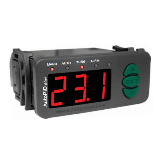
The AutoPID plus is a digital controller for heating and cooling processes. It uses a PID (proportional,
integral, and derivative) type controller, which enables to control the temperature with minimal fluctuation.
Product complies with UL Inc. (United States and Canada).
2. APPLICATION
• Freezing and heating chambers
• Refrigeration plants
• Set of compressors etc.
3. TECHNICAL SPECIFICATIONS
- Power Supply: 90 to 264Vac (50/60 Hz)
- Controlled Temperature: -50 to 100°C (with resolution of 0.1°C)
- Indication Accuracy: 0.1°C between -10 and 100°C
and 1°C for the rest of the scale
- Controlling Accuracy: 0.1°C for the whole scale
- Proportional Outputs: Voltage output: 0~10Vdc 5mA
PWM: Adjustable period 5mA
- Alarm Output: 5(3)A 250Vac 1/8HP
- Dimensions: 71 x 28 x 71mm
- Operation temperature: 0 to 50°C
- Operation humidity: 10 to 90% RH (without condensation)
4. CONFIGURATION
4.1 - Setpoint adjustment
Press
for 2 seconds until it displays
SET
set is displayed. Use
and
keys to change this value and press
when ready.
4.2 - Accessing the function menu
Press
and
keys simultaneously for 2 seconds until it displays
When
is displayed, press
(shortly) and enter the code (123) by using the
SET
Press
to confirm. You can use
and
SET
to adjust other functions.
To exit the menu and return to the normal operation, hold the
4.3 - Advanced functions
Description
Fun
Access code (123)
Static gain
Integral time
Derivative time
Anti-windup time
Setpoint gain in the proportional control
Control type (0 = cooling, 1 = heating)
Output amplitude for autotuning
Temperature hysteresis for autotuning
Steady temperature validation time
Autotuning starting method
Max. amount of time for stabilizing the temperature before autotuning activation
Low temperature alarm
Hysteresis for resetting the low temperature alarm
High temperature alarm
Hysteresis for resetting the high temperature alarm
ON-OFF cycle time for alarm output
PWM output period
Output value in the manual mode
Output value when error occurs
Minimum setpoint allowed to the final user
Maximum setpoint allowed to the final user
Indication offset
RS-485 network address
4.4 - Function description
Access code (123)
The access code is needed when you want to change the configuration settings. If you just want to view
the parameters you don't need to input the access code.
Static gain (K)
This gain actuates in the system error (proportional control) and is related to stabilization time and
control circuit speed. The static gain can be calculated automatically by the autotuning.
Integral time (Ti)
The integrative control is responsible for canceling an error when the system is in a steady condition and
is also responsible for the system stabilization time. This parameter can be calculated automatically by
the autotuning.
Derivative time (Td)
This is responsible for stabilizing the system in the setpoint and canceling the overshoot. It can be
calculated automatically by autotuning, just as the other parameters.
AutoPID plus
PID TYPE DIGITAL TEMPERATURE
CONTROLLER
Ver.02
and then release the key. The operation temperature you
to configure the new value
SET
and then release the keys.
keys to access other functions. Use the same procedure
key pressed for a while to display
SET
Min
Max
Default
-99
999
0.0
99.9
1.0
0
999
999
0
0
999
0.0
1.0
0
1
10
100
0.1
20.0
1
999
0
3
1
999
999
-50.0
100.0
-50.0
1.0
10.0
-50.0
100.0
100.0
1.0
10.0
0
210
1
999
0
100
0
100
-50.0
100.0
-50.0
-50.0
100.0
100.0
-5.0
5.0
1
247
Proportional output anti-saturation system time (Tt)
This is responsible for preventing the proportional control output from becoming saturated due to
integral control action (windup). The value recommended for this function is:
The value for this parameter is calculated automatically at the end of autotuning by using Ti and Td
parameters according to the formula above.
Setpoint influence in the static gain
This is the setpoint gain when calculating the system error. It is used to reduce the effect of an eventual
noise from the temperature sensor. When you reduce this parameter value, you increase the immunity
to noise.
Control type
Indicates the process type that the controller will operate.
Output amplitude for autotuning
Initial amplitude of the signal to be applied in the proportional output during the autotuning stage.
This value is recalculated automatically by the controller during the autotuning and it must be chosen so
that the system can distinguish the temperature oscillation around the setpoint and the hysteresis.
Temperature hysteresis for autotuning
This hysteresis is used together with the setpoint to control the temperature oscillation in the autotuning.
Steady temperature validation time
This is the time used by the controller to make sure that system temperature is steady and stabilized.
and
keys.
Autotuning starting type
This function defines the mode in which the autotuning must be started.
.
Unit
0
-
-
12
x 10 sec.
3
x 10 sec.
Max. time for system stabilization
4
x 10 sec.
Maximum time for temperature stabilization before executing autotuning (if configured).
1.0
-
Low temperature alarm
0
-
Temperature for activating the low temperature alarm.
40
%
5.0
°C
Hysteresis for resetting the low temperature alarm
6
x 10 sec.
Hysteresis for resetting the low temperature alarm.
0
-
High temperature alarm
mim.
°C
Temperature for activating the high temperature alarm.
1.0
°C
Hysteresis for resetting the high temperature alarm
°C
Hysteresis for resetting the high temperature alarm.
1.0
°C
0
sec.
ON-OFF cycle time for alarm output
1
x 10 ms.
Cycle time in which the alarm output is turned ON and OFF. If the alarm output is intended to remain
0
%
always ON, this parameter must be set to "0".
50
%
PWM output period
°C
Total time the PWM output remains in the ON and OFF state. The time for each state depends on the
°C
proportional output value.
0.0
°C
1
-
Output value in the manual mode
PWM and proportional output value when the controller is in the manual mode.
Output value when a sensor error occurs
PWM and proportional output value when an error occurs in the temperature readings.
Minimum setpoint allowed to the final user
Lower limit to avoid that extremely low temperatures be configured by mistake.
Maximum setpoint allowed to the final user
Upper limit to avoid that extremely high temperatures be configured by mistake.
Cooling
Heating
Only manual start;
Performs autotuning when automatic control is activated;
Performs autotuning if the temperature does not stabilize inside the period of time configured
in F12;
Performs autotuning when automatic control is activated or if the temperature does not
stabilize inside the period of time configured in F12.
E251415
Advertisement

Related Manuals for Full Gauge Controls AutoPID plus


Summary of Contents for Full Gauge Controls AutoPID plus
- Page 1 This is responsible for preventing the proportional control output from becoming saturated due to The AutoPID plus is a digital controller for heating and cooling processes. It uses a PID (proportional, integral control action (windup). The value recommended for this function is: integral, and derivative) type controller, which enables to control the temperature with minimal fluctuation.
- Page 2 Warning: it is not allowed to have more than one device with the same address in a network. 5. AUTOTUNING The AutoPID plus uses the Critical Period method to calculate automatically its PID parameters. This method consists in making the system temperature oscillate around the setpoint so that the necessary...