Table of Contents
Advertisement
B
C
URNER
ONTROLS
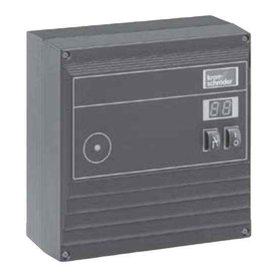
BCU 465
Technical Information
T-Product 2006 April
Automatic burner control unit with integrated igni-
tion transformer packaged in a single compact
metal housing (IP 54/NEMA 3 rating)
For use with direct spark ignited burners
For continuous operation
For use with modulating or frequency fired control
systems
Includes air valve control
Optional proof of closure switch (POC) control input
Optional digital input for 1,400 °F auto ignition lockout
Displays program status, unit parameters, fault
code or flame signals
Optional optical interface for diagnostic information
and parameter settings
Manual mode for burner adjustments and trouble-
shooting
Select restart or immediate fault lockout in the
event of a flame failure
Removable bottom mounting plate with five (5)
½" conduit openings make installation of electrical
connections simple
Removable terminal blocks to facilitate electrical
field wiring
Meets NFPA 86 standard
CE certified models available
Advertisement
Table of Contents

Subscribe to Our Youtube Channel
Related Manuals for Kromschroder BCU 465


Summary of Contents for Kromschroder BCU 465
- Page 1 URNER ONTROLS BCU 465 Technical Information T-Product 2006 April Automatic burner control unit with integrated igni- tion transformer packaged in a single compact metal housing (IP 54/NEMA 3 rating) For use with direct spark ignited burners For continuous operation For use with modulating or frequency fired control...
-
Page 2: Table Of Contents
Flame Proving Period, Parameter 23 ....23 Terminal Wiring BCU 465 ....12 Manual Mode Limit, Parameter 34 . - Page 3 Contact ....... . .31 T-Product · BCU 465 · 2006 April...
-
Page 4: Application
(low-fire). Once the burner is ignited, the air butterfly valve can be modulated throughout the control range. The gas is controlled with an air/fuel ratio regulator cross-connected to the burner air supply piping. T-Product · BCU 465 · 2006 April... -
Page 5: Bcu 465 For Frequency Firing Systems
The On and Off time is determined by the frequency control algorithm. However, BCU 465 provides a minimum off time and a minimum on time to slow down the process and avoid process errors in PLC control algorithm. T-Product · BCU 465 · 2006 April... -
Page 6: Technical Data
Notes: Values in () apply to 60 Hz. On burners with star electrodes, we recommend the use of ignition transformers with 7.5 kV. If external ignition transformer is used, minimum cycle time shall be 9 seconds. T-Product · BCU 465 · 2006 April... -
Page 7: System Design Information
Use unshielded high voltage cable When using one electrode for igni- and RFI suppressed plug 1 kΩ. tion and flame monitoring, a direct Do not place into metal conduit or connection from burner ground to T-Product · BCU 465 · 2006 April... -
Page 8: Safety Considerations
UV This ensures the burner is at low fire radiation as a flame simulation. before switching off when operating ▼ in an off-low-high-low-off control system. T-Product · BCU 465 · 2006 April... - Page 9 flame signal. If the tem- safety requirements and approved perature in the furnace chamber falls controllers. below the ignition temperature, the A safety temperature monitor with a digital input must be de-energized T-Product · BCU 465 · 2006 April...
-
Page 10: Installation Information
6” away from furnace casing with ample airflow available a) Screw on BCU with (4) screws around enclosure. from inside, minimum length 5/8”. To ensure this, the fastening set may be used: T-Product · BCU 465 · 2006 April... - Page 11 Installation 74960422 ø 0.15" 74960414 (4 mm) Fastening sets External fastening may be used to save installation costs because the BCU does not need to be opened to install it to the system. T-Product · BCU 465 · 2006 April...
-
Page 12: Terminal Wiring Bcu 465
** BCU 465T..O Terminal Wiring BCU 465 Electrical connections are via hard wiring to screw terminals. Flexible conduit connections can be made easily through the bottom mounting plate of the BCU housing. T-Product · BCU 465 · 2006 April... -
Page 13: Operation
flashes displaying the sequence or fault code. The flame signal and all the following parameters of the BCU can be viewed on the display consecutively by repeatedly pressing the Reset/Information button. T-Product · BCU 465 · 2006 April... -
Page 14: Program Status And Fault Indication
High temperature mode Fuse F1 Fault or no input from limits circuit Permanent remote reset Pulse firing cycle too short In manual mode, two dots blink simutaneously in program status 01 – 04. T-Product · BCU 465 · 2006 April... -
Page 15: Normal Start-Up Sequence For Bcu 465
flame signal remains, the BCU will go the flame signal, push and hold the to fault lockout. reset/info button located on the front of each BCU unit for 1 seconds. The display will change to “01”. Release T-Product · BCU 465 · 2006 April... -
Page 16: Air Valve Control Of Bcu 465
Selecting a time between 0 seconds and 250 seconds will open the air valve simultaneously with the start signal terminal #4. After the air valve closed, then trial for ignition will begin. T-Product · BCU 465 · 2006 April... -
Page 17: External Control Of Air Valve Function
With setting “0”, -it remains closed. It cannot be activated, how- ever, when the automatic burner control unit is deactivated. When activated, the display indicates “A0” (not flashing). T-Product · BCU 465 · 2006 April... -
Page 18: Additional Features
• To terminate manual mode: sion) and ignites the burner. The Switch off BCU. display changes to 0.2. or 0.3. • Press button for 2 seconds. The BCU opens valve V2 (if ➔ not POC-version). The display T-Product · BCU 465 · 2006 April... -
Page 19: 1400 °F (750 °C) Auto Ignition Flame Management Bypass Input
If parameter 33 = 3, the BCU will continue normal operation after the process temperature has dropped below the auto ignition temperature. The flame signal will now be monitored. This is recommended if flame rods are used. T-Product · BCU 465 · 2006 April... -
Page 20: Order Information
1400 °F Auto ignition bypass digital input, shut down+restart 1400 °F Auto ignition bypass digital input, operation resumes Proof-of-closure (POC) Control Input Additional terminals Special version on request See also Ignition Transformer ratings T-Product · BCU 465 · 2006 April... -
Page 21: Factory Options And Field Programmable
flame the auto ignition temperature. The loss before a safety shutdown ap- flame signal will now be monitored. plies. This is recommended if flame rods are used. T-Product · BCU 465 · 2006 April... -
Page 22: Field Programmable Options
Field programmable time in the range of minimum trial for ignition period t up to a maximum of 25 seconds while the burner remains in operation. With short-term activation of the start-up signal input (ϑ) (e.g. T-Product · BCU 465 · 2006 April... -
Page 23: Flame Proving Period, Parameter 23
• All parameters can be recalled day: parameter 35 = 1: restart, pa- consecutively in this way. rameter 35 = 0 continue. • If the button is pressed only briefly, the display indicates what T-Product · BCU 465 · 2006 April... -
Page 24: Parameter Setting
Digital input as 1400 °F auto igition flame management bypass 3 = continue operation immediately 0 = w/o limit; Manual operation limited to 5 minutes or w/o limit 1 = limit 5 minutes ▼ T-Product · BCU 465 · 2006 April... - Page 25 * Field programmable option: Adjustable with software BCSoft and PC optical adapter ** Factory option: Please state when ordering *** Time ignition transformer is evergized: Saftey period = 10 sec: 6 sec; safety period = 5 sec: 3 sec. T-Product · BCU 465 · 2006 April...
-
Page 26: Accessories
Part No. 84315100 UVS 8T Ultraviolet flame de- tector Part No. 84333120 Angular plug ø 4 mm, inter- ference-suppressed Part No. 04115308 Straight plug ø 4 mm, inter- ference-suppressed Part No. 04115307 T-Product · BCU 465 · 2006 April... -
Page 27: Troubleshooting
Reset/Info button until the below. display starts to flash. Note: If the BCU does not respond even though all faults have been cor- rected, – remove unit and return it to the manufacturer for inspection. T-Product · BCU 465 · 2006 April... -
Page 28: The Display Flashes And Displays 01
Remove the valve im- • Reset repeatedly until gas line mediately if you have any doubt fills with gas. of correct close position. T-Product · BCU 465 · 2006 April... -
Page 29: At Start-Up - Flame Verified Visually, Display Flashes And Indicates 02 Or 03
• Correct fault. allowing non-combusted gas ! The supply voltage of the unit is to escape. Explosion risk! below the rated voltage. • Ensure correct voltage supply (maximum ratings are given in the technical data). T-Product · BCU 465 · 2006 April... -
Page 30: The Display Flashes And Indicates 52
? The display flashes and indi- cates 10? ! The BCU is repeatedly reset (more than 5 times in 15 min- utes). • Avoid automatic reset by PLC or without monitoring the burner. Reset BCU manually. T-Product · BCU 465 · 2006 April... -
Page 31: Contact
Situations dangerous to personnel and property can result from the misapplication and incorrect operation of combustion equipment. Kromschroder advises compliance with the National Fire Protection Association standards that apply for related equipment and Insurance Underwriters recommendation, and care of operation.
Need help?
Do you have a question about the BCU 465 and is the answer not in the manual?
Questions and answers