Sign In
Upload
Download
Table of Contents
Contents
Add to my manuals
Delete from my manuals
Share
URL of this page:
HTML Link:
Bookmark this page
Add
Manual will be automatically added to "My Manuals"
Print this page
×
Bookmark added
×
Added to my manuals
Manuals
Brands
Tucker Manuals
Door Opening System
SW10
Installation manual
Tucker SW10 Installation Manual
Hide thumbs
1
2
3
4
5
6
7
8
9
10
11
12
13
14
15
16
17
18
19
20
21
22
23
24
25
26
27
28
29
30
31
32
33
34
35
36
37
38
39
40
41
42
43
44
45
46
47
48
49
50
51
52
53
54
55
56
57
58
59
60
page
of
60
Go
/
60
Contents
Table of Contents
Troubleshooting
Bookmarks
Table of Contents
Tucker Auto-Mation Sw10 (Full Power) & Sw19 (Low Energy)
Table of Contents
Product Description & Specifications
Header Installation
Push Arm Installation
Pull Arm Installation
120 Volt AC Connection
Power on & Indications
Set-Up Procedures
Wiring Connections
Adjusting the Mechanical Door Stop
Troubleshooting
Job Documentation & Closeout / Accessories / Company Contact
Appendix - Wiring Diagrams
Appendix - Fire Rated Door Application
Appendix - Tap Programming Device - KP Evo
Tap Controller Installation Guide Kp Evo Kp
1 Kp Evo
Installation and Connections
Switching on and the Home Screen
SELECTION Menu
FUNCTIONS Menu
A P EVO Menu
B Access Permissions and Passwords
Logic Board Leds
Inputs and Outputs Status Check
Automation Status Check
C I/O Board Leds
D Logic Board Leds
E Status
Warnings
F Warnings
Errors
G Errors
Other Board Data
Firmware Versions
Log Data
H Selecting Theupload/Download Function
3 Upload / Download
4 Put Ting into Service
Final Checks
Final Operations
Installing a Plastic Cover
Installing an Aluminium Cover
5 Maintenance
Inserting / Replacing the Battery
Replacing the Fuse
Routine Maintenance
I Scheduled Maintenance
6 Intercom
Intermode
Interlock
Interlock with no Memory
Interlock with Memory
Leaves
Interlock
KP Evo
Advertisement
Quick Links
1
Table of Contents
2
Product Description & Specifications
3
Push Arm Installation
4
Set-Up Procedures
5
Wiring Connections
6
Adjusting the Mechanical Door Stop
7
Troubleshooting
8
Appendix - Wiring Diagrams
Download this manual
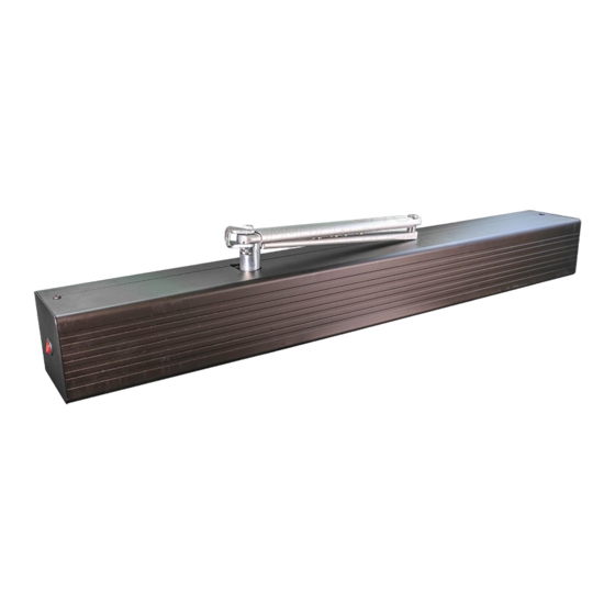
SW10 (Full Power) & SW19 (Low Energy)
TUCKER AUTO-MATION
INSTALLATION GUIDE
Surface Mounted Applications
920.1020.15
1
Table of
Contents
Previous
Page
Next
Page
1
2
3
4
5
Advertisement
Chapters
Tucker Auto-Mation Sw10 (Full Power) & Sw19 (Low Energy)
2
Tap Controller Installation Guide Kp Evo Kp
37
Table of Contents
Need help?
Do you have a question about the SW10 and is the answer not in the manual?
Ask a question
Questions and answers
Related Manuals for Tucker SW10
Door Opening System Tucker SW19 Installation Manual
(60 pages)
Door Opening System Tucker KP evo Installation Manual
Tap controller (28 pages)
This manual is also suitable for:
Sw19
Table of Contents
Save PDF
Print
Rename the bookmark
Delete bookmark?
Delete from my manuals?
Login
Sign In
OR
Sign in with Facebook
Sign in with Google
Upload manual
Upload from disk
Upload from URL


Need help?
Do you have a question about the SW10 and is the answer not in the manual?
Questions and answers