Table of Contents
Advertisement
Quick Links
e
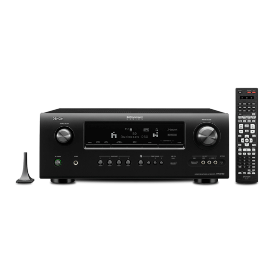
AVR-3312CI
AVR-3312
• For purposes of improvement, specifications and design are subject to change without notice.
• Please use this service manual with referring to the operating instructions without fail.
• Some illustrations using in this service manual are slightly different from the actual set.
S0377-1V06DM/DG1110
SERVICE MANUAL
MODEL
INTEGRATED NETWORK AV RECEIVER
JP
E3
E2
P
P
e
D&M Holdings Inc.
EK
EA
E1C E1K
s
P
Ver. 6
Please refer to the
MODIFICATION NOTICE.
CI
s
Advertisement
Table of Contents

Related Manuals for Denon AVR-3312


Summary of Contents for Denon AVR-3312
- Page 1 SERVICE MANUAL MODEL E1C E1K AVR-3312CI AVR-3312 INTEGRATED NETWORK AV RECEIVER • For purposes of improvement, specifications and design are subject to change without notice. • Please use this service manual with referring to the operating instructions without fail. • Some illustrations using in this service manual are slightly different from the actual set.
-
Page 2: Table Of Contents
GUIDE R (FOIL SIDE) ............121 CONTENTS USB (FOIL SIDE) ..............121 SELECTOR (COMPONENT SIDE) ........122 SAFETY PRECAUTIONS ............3 RS232C (COMPONENT SIDE)..........122 NOTE FOR SCHEMATIC DIAGRAM .........4 SELECTOR (FOIL SIDE) ............122 TECHNICAL SPECIFICATIONS ..........5 RS232C (FOIL SIDE) ............122 DIMENSION ................5 SIDE_CNT (COMPONENT SIDE) ........123 SIDE_CNT (FOIL SIDE) ............123 CAUTIONS IN SERVICING ............6 Initializing INTEGRATED NETWORK AV RECEIVER ....6... -
Page 3: Safety Precautions
SAFETY PRECAUTIONS The following items should be checked for continued protection of the customer and the service technician. LEAKAGE CURRENT CHECK Before returning the set to the customer, be sure to carry out either (1) a leakage current check or (2) a line to chassis resistance check. -
Page 4: Note For Schematic Diagram
NOTE FOR SCHEMATIC DIAGRAM WARNING: Parts indicated by the z mark have critical characteristics. Use ONLY replacement parts recommended by the manufacturer. CAUTION: Before returning the set to the customer, be sure to carry out either (1) a leakage current check or (2) a line to chassis resistance check. If the leakage current exceeds 0.5 milliamps, or if the resistance from chassis to either side of the power cord is less than 460 kohms, the set is defective. -
Page 5: Technical Specifications
TECHNICAL SPECIFICATIONS s n Audio Section n Tuner section (E3 model) • Power amplifier [FM](Note: μV at 75 Ω, 0 dBf = 1 x 10 –15 Rated output : Receiving Range : [FM] 87.5 MHz – 107.9 MHz [AM]530 kHz – 1710 kHz Front : 125 W + 125 W (8 Ω, 20 Hz –... -
Page 6: Cautions In Servicing
PRESET CHANNEL 2 Service Jig d When you repair the printing board, you can use the following JIG (Extension cable kit). Please order it from Denon Official Service Distributor in your region if necessary. 8U-110084S EXTENSION UNIT KIT 1 Set... -
Page 7: Disassembly
DISASSEMBLY • Disassemble in order of the arrow in the following figure. • In the case of the re-assembling, assemble it in order of the reverse of the following flow. • In the case of the re-assembling, observe "attention of assembling". •... - Page 8 About the photos used for "descriptions of the DISASSEMBLY" section • The shooting direction of each photograph used herein is indicated on the left side of the respective photograph as "Shooting direction: ***". • Refer to the diagram below about the shooting direction of each photograph. •...
-
Page 9: Front Panel Assy
1. FRONT PANEL ASSY Proceeding : CABINET TOP FRONT PANEL ASSY → Remove the screws. View from the bottom Cut the wire clamp band, then disconnect the connector wires and FFC cables. Remove the screws. STYLE PIN : Loosen CN602 TAPE : Remove FFC cable CN390... -
Page 10: Heat Sink Assy
2. HEAT SINK ASSY Proceeding : CABINET TOP HEAT SINK ASSY → Remove the screws. View from the bottom Cut the wire clamp band, then remove the screws. Disconnect the connector wires. Shooting direction: D Shooting direction: C CN602... - Page 11 Cut the wire clamp band, then disconnect the connector wire and FFC cables . STYLE PIN : Loosen HEAT SINK Assy TAPE : Remove FFC cable CN390 FFC cable Cut the wire clamp bands, then disconnect the connector wires. CN461 CN701 CN703 CN702...
-
Page 12: Hdmi Unit Assy
3. HDMI UNIT ASSY HDMI UNIT ASSY Proceeding : CABINET TOP → Remove the screws, then remove the BACK PANEL and the HDMI BRACKET. Shooting of photograph: A Cut the wire clamp band, then disconnect the connector wires and the FFC cables. Remove the PCB DOCK from the PCB SIDE CNT and PCB RS232C(Board to board). - Page 13 Disconnect the connector wire. Remove the screws. CN931 Remove the screws.
- Page 14 Cut the wire clamp band, then disconnect the connector wires. CN941 CN932 CN940 CN903 CN781 Cut the wire clamp band, then disconnect the connector wires. CN461 CN701 CN703 CN702...
-
Page 15: Trans Main
Cut the wire clamp bands, then disconnect the connector wires, and remove the screws. CN203 CN902 Remove the screw. Please refer to "EXPLODED VIEW" for the disassembly method of each P.W.B included in HDMI UNIT ASSY. 4. TRANS MAIN Proceeding : CABINET TOP HDMI UNIT ASSY POWER TRANS... -
Page 16: Special Mode
STATUS paths. (Troubleshooting) CHANNEL 1 The signal paths of the set can be easily confirmed after repair. When using multiple DENON AV receivers in the same room, make PRESET Remote ID Setup mode STATUS this setting so that only the desired AV receiver operates.(Refer to 22... -
Page 17: Μcom/Dsp Version Display Mode
1. µcom/DSP Version display mode 1.1. Operation specifications µcom/DSP version display mode: When the set is started up in this mode, the version information is displayed. Starting up: Press the "ON/STANDBY" button to turn on the power while pressing the "STATUS" and "PRESET CH +" buttons. Now, press the "STATUS"... - Page 18 i Ethernet(DM860) 1st Boot Loader, Hardware ID : E t h e r n e t F B L Upper Lower * * * * * * - A A o Ethernet(DM860) 2nd Boot Loader, Rhapsody Flag : E t h e r n e t S B L Upper Lower...
- Page 19 1.3. Error display s See the following table for each "Error information" display and its explanation (status). Display order is q , w , e , r , t , y , u , i . Condition Status FL Display Trouble shooting •...
-
Page 20: Errors Checking Mode (Displaying The Protection History)
2. Errors checking mode (Displaying the protection history) 2.1. Operation specifications Error mode (Displaying the protection history): When the set is started up in this mode, the error information is displayed. Starting up: • Common in all the models Press the "ON/STANDBY" button to turn on the power while pressing the "STATUS" and "TUNER PRESET-" buttons. The error (protection history display) mode is set. - Page 21 2.3. Clearing the protection history There are two ways to clear the protection history, as described below. Start up the set in error (protection display) mode and display the error, then press and hold down the "INTERNET RADIO" button for 3 seconds. P R O T E C T H I S T O R Y Upper...
-
Page 22: Remote Id Setup Mode
3. Remote ID Setup mode 3.1. Specifications When using multiple DENON AV receivers in the same room, make this setting so that only the desired AV receiver operates. 2.2. Setting the AV receivers Starting up: Press and hold both "STATUS" and "PRESET 1" buttons for over 3 second with the power turned on. -
Page 23: Protection Diagram
AVR3312/2312/SR6006 PROTECTION DIAGRAM PROTECTION DIAGRAM d 2011_5_26 D&M P1 D.Hara PAMP UNIT DIGITAL UNIT TR_THERMAL THER_PROT_C 115pin/P12 PROTECTION LOGIC THER_PROT_D 141pin/P12 DC ⇒ L_active shutdown TR_THERMAL uCOM ASO ⇒ L_active shutdown THER PROTD ⇒ L_active shutdown THER PROTC ⇒ L_active shutdown THER_PROT_A 45pin/P12 THER PROTB ⇒... -
Page 24: Block Diagram
4. DIAGNOSTIC MODE (Video/Audio (signal) path confirmation mode) d This mode is used for confirming the Video and Audio (signal) paths. (Troubleshooting) Confirming the operation of unit can be easily done after repair. Backup data will not be lost. 4.1. Starting diagnostic mode Press the "PRESET CHANNEL 1" and "STATUS" button while simultaneously pressing those two buttons of this unit. Q1, Q2 and Q3 are lit in FL display. -
Page 25: Power
Output sequence of remote control codes Confirmation item Details of how to operate remote controller *a) Contents of confirmation Setting and display Remarks ※ It is useful to form a macro program. *b) Video Convert(IP Scaler) : ON, All Sources qZONE2 POWER OFF Confirm the input pass one by one. -
Page 26: Audio
3.5. Audio system confirmation items fig.XX : Refer to the block diagram of the fig.XXth. Output sequence of remote control codes Confirmation item Contents of confirmation Setting and display Details of how to operate remote controller Remarks ※ It is useful to form a macro program. Input Mode : Fixed ANALOG qZONE2 POWER OFF ·Input : Analog / Output : Speakers (Front L/R) - Page 27 Output sequence of remote control codes Confirmation item Contents of confirmation Setting and display Details of how to operate remote controller Remarks ※ It is useful to form a macro program. Amp assign : NORMAL qZONE2 POWER OFF ·Input : Analog / Output : Speakers (Front L/R) A/D (signal) Path 1.Press [AMP] 2.Press [ZONE SELECT] , Select "ZONE2"...
- Page 28 Output sequence of remote control codes Confirmation item Contents of confirmation Setting and display Details of how to operate remote controller Remarks ※ It is useful to form a macro program. qZONE2 POWER OFF ·Input : Analog / Output : Speakers (SURR BACK L/R) Amp Assign (signal) Path Amp assign : 2CH 1.Press [AMP]...
- Page 29 BLOCK DIAGRAM d fig.1 AVR3312/2312 VIDEO BLOCK IC551 AVR3312 AVDM-2000 BD_V MONITOR MONITOR VOUT4 Z2 MONITOR DVD_V CVBS IN DVR_V Z2 MONITOR Z2 MONITOR SAT_V VOUT5 AVR3312 AVR2312 BD_V V.AUX(FRONT) V.AUX_V DVD_V DETECT SAT_V CIRCUIT DVR_V ONLY JPN AVR3312 VDO_CVBS VOUT1 DEC_CVBS_IN BU4052BCF...
- Page 30 fig.2 (1/2) AVR3312/2312 VIDEO BLOCK IC551 AVR3312 AVDM-2000 BD_V MONITOR MONITOR VOUT4 Z2 MONITOR DVD_V CVBS IN DVR_V Z2 MONITOR Z2 MONITOR SAT_V VOUT5 AVR3312 AVR2312 BD_V V.AUX(FRONT) V.AUX_V DVD_V DETECT SAT_V CIRCUIT DVR_V ONLY JPN AVR3312 VDO_CVBS VOUT1 DEC_CVBS_IN BU4052BCF VIN2L1 V.AUX_V MONIL1...
- Page 31 fig.2 (2/2) AVR3312/2312 HDMI VIDEO BLOCK IC121 IC151 IC101 HDMI IN ADV7844 ADV8002-1 : AVR3312 AD8195 Port A ADV8002-4 : AVR2312 Buffer HDMI FRONT IN Port B HD_PCLK IC111 HDMI IN1 HD_HSYNC HD_VSYNC ADV3002 VIDEO Port C HD_DE HDMI OUT1 HD/CS HD_SFL PROCESSING VS/FIELD...
- Page 32 fig.3 AVR3312/2312 HDMI VIDEO BLOCK IC121 IC151 IC101 HDMI IN ADV7844 ADV8002-1 : AVR3312 AD8195 Port A ADV8002-4 : AVR2312 Buffer HDMI FRONT IN Port B HD_PCLK IC111 HDMI IN1 HD_HSYNC HD_VSYNC ADV3002 VIDEO Port C HD_DE HDMI OUT1 HD/CS HD_SFL PROCESSING VS/FIELD...
- Page 33 fig.4 (1/2) AVR3312/2312 VIDEO BLOCK IC551 AVR3312 AVDM-2000 BD_V MONITOR MONITOR VOUT4 Z2 MONITOR DVD_V CVBS IN DVR_V Z2 MONITOR Z2 MONITOR SAT_V VOUT5 AVR3312 AVR2312 BD_V V.AUX(FRONT) V.AUX_V DVD_V DETECT SAT_V CIRCUIT DVR_V ONLY JPN AVR3312 VDO_CVBS VOUT1 DEC_CVBS_IN BU4052BCF VIN2L1 V.AUX_V MONIL1...
- Page 34 fig.4 (2/2) AVR3312/2312 HDMI VIDEO BLOCK IC121 IC151 IC101 HDMI IN ADV7844 ADV8002-1 : AVR3312 AD8195 Port A ADV8002-4 : AVR2312 Buffer HDMI FRONT IN Port B HD_PCLK IC111 HDMI IN1 HD_HSYNC HD_VSYNC ADV3002 VIDEO Port C HD_DE HDMI OUT1 HD/CS HD_SFL PROCESSING VS/FIELD...
- Page 35 fig.5 (1/2) AVR3312/2312 HDMI VIDEO BLOCK IC121 IC151 IC101 HDMI IN ADV7844 ADV8002-1 : AVR3312 AD8195 Port A ADV8002-4 : AVR2312 Buffer HDMI FRONT IN Port B HD_PCLK IC111 HDMI IN1 HD_HSYNC HD_VSYNC ADV3002 VIDEO Port C HD_DE HDMI OUT1 HD/CS HD_SFL PROCESSING VS/FIELD...
- Page 36 fig.5 (2/2) AVR3312/2312 VIDEO BLOCK IC551 AVR3312 AVDM-2000 BD_V MONITOR MONITOR VOUT4 Z2 MONITOR DVD_V CVBS IN DVR_V Z2 MONITOR Z2 MONITOR SAT_V VOUT5 AVR3312 AVR2312 BD_V V.AUX(FRONT) V.AUX_V DVD_V DETECT SAT_V CIRCUIT DVR_V ONLY JPN AVR3312 VDO_CVBS VOUT1 DEC_CVBS_IN BU4052BCF VIN2L1 V.AUX_V MONIL1...
- Page 37 fig.6 AVR3312/2312 HDMI VIDEO BLOCK IC121 IC151 IC101 HDMI IN ADV7844 ADV8002-1 : AVR3312 AD8195 Port A ADV8002-4 : AVR2312 Buffer HDMI FRONT IN Port B u-COM HD_PCLK IC111 HDMI IN1 HD_HSYNC HD_VSYNC ADV3002 VIDEO Port C HD_DE HDMI OUT1 HD/CS HD_SFL PROCESSING...
- Page 38 fig.7 AVR3312/2312 HDMI VIDEO BLOCK IC121 IC151 IC101 HDMI IN ADV7844 ADV8002-1 : AVR3312 AD8195 Port A ADV8002-4 : AVR2312 Buffer HDMI FRONT IN u-COM Port B HD_PCLK IC111 HDMI IN1 HD_HSYNC HD_VSYNC ADV3002 VIDEO Port C HD_DE HDMI OUT1 HD/CS HD_SFL PROCESSING...
- Page 39 fig.8 (1/2) AVR3312/2312 ANALOG AUDIO BLOCK H/P OUT EXTFL AMP/PRE EXTFR ANA_FL AMPFL SPK OUT DAFL TONE EXTC EXTFL EXTSW AMPFR V.AUX AMP/PRE ANAFR ADINL/R EXTSL DAFR DAZONE2 TONE EXTFR NOT USED EXTSR DAZONE3 AVR3312 ONLY : FH_L FRONT HEIGHT EXTBSL AMP/PRE EXTBSR EXTC...
- Page 40 fig.8 (2/2) AVR3312/2312 DIGITAL AUDIO BLOCK DATAAD. IC451 ADINL FSDIR1,64FSDIR1,256FSDIR1 AK5358BET ADINR DIGTAL IN OPT1 DAFL DAFR OPT2 DASW IC403 IC441 DASL DIR1 COAX1 LC89058 DASR AK4358VQ DASBL COAX2 DASBR DAZ2 DATAF/CSW/S/SB DAZ3 DAC256FS DAC64FS DACFS AVR3312 Jitter DATAF/CSW/S/SB Reducer DAC256FS DAC64FS X4002 DACFS...
- Page 41 fig.9 AVR3312/2312 DIGITAL AUDIO BLOCK DATAAD. IC451 ADINL FSDIR1,64FSDIR1,256FSDIR1 AK5358BET ADINR DIGTAL IN OPT1 DAFL DAFR OPT2 DASW IC403 IC441 DASL DIR1 COAX1 LC89058 DASR AK4358VQ DASBL COAX2 DASBR DAZ2 DATAF/CSW/S/SB DAZ3 DAC256FS DAC64FS DACFS AVR3312 DATAF/CSW/S/SB Jitter Reducer DAC256FS DAC64FS X4002 DACFS...
- Page 42 fig.10 AVR3312/2312 ANALOG AUDIO BLOCK H/P OUT EXTFL AMP/PRE EXTFR ANA_FL AMPFL SPK OUT DAFL TONE EXTC EXTFL EXTSW V.AUX AMPFR AMP/PRE ANAFR ADINL/R EXTSL DAFR DAZONE2 TONE EXTFR NOT USED EXTSR DAZONE3 AVR3312 ONLY : FH_L EXTBSL FRONT HEIGHT AMP/PRE EXTBSR EXTC...
- Page 43 fig.11 (1/2) AVR3312/2312 ANALOG AUDIO BLOCK H/P OUT EXTFL EXTFR AMP/PRE ANA_FL AMPFL SPK OUT DAFL TONE EXTC EXTFL EXTSW AMPFR V.AUX AMP/PRE ANAFR ADINL/R EXTSL DAFR DAZONE2 TONE EXTFR NOT USED EXTSR DAZONE3 AVR3312 ONLY : FH_L EXTBSL FRONT HEIGHT AMP/PRE EXTBSR EXTC...
- Page 44 fig.11 (2/2) AVR3312/2312 DIGITAL AUDIO BLOCK DATAAD. IC451 ADINL FSDIR1,64FSDIR1,256FSDIR1 AK5358BET ADINR DIGTAL IN OPT1 DAFL DAFR OPT2 DASW IC403 IC441 DASL DIR1 COAX1 LC89058 DASR AK4358VQ DASBL COAX2 DASBR DAZ2 DATAF/CSW/S/SB DAZ3 DAC256FS DAC64FS DACFS AVR3312 Jitter DATAF/CSW/S/SB Reducer DAC256FS DAC64FS X4002 DACFS...
- Page 45 fig.12 (1/2) AVR3312/2312 ANALOG AUDIO BLOCK H/P OUT EXTFL AMP/PRE EXTFR ANA_FL AMPFL SPK OUT DAFL TONE EXTC EXTFL EXTSW AMPFR V.AUX AMP/PRE ANAFR ADINL/R EXTSL DAFR DAZONE2 TONE EXTFR NOT USED EXTSR DAZONE3 AVR3312 ONLY : FH_L FRONT HEIGHT EXTBSL AMP/PRE EXTBSR EXTC...
- Page 46 fig.12 (2/2) AVR3312/2312 DIGITAL AUDIO BLOCK DATAAD. IC451 ADINL FSDIR1,64FSDIR1,256FSDIR1 AK5358BET ADINR DIGTAL IN OPT1 DAFL DAFR OPT2 DASW IC403 IC441 DASL DIR1 COAX1 LC89058 DASR AK4358VQ DASBL COAX2 DASBR DAZ2 DATAF/CSW/S/SB DAZ3 DAC256FS DAC64FS DACFS AVR3312 Jitter DATAF/CSW/S/SB Reducer DAC256FS DAC64FS X4002 DACFS...
- Page 47 fig.13 (1/2) AVR3312/2312 ANALOG AUDIO BLOCK H/P OUT EXTFL AMP/PRE EXTFR ANA_FL AMPFL SPK OUT DAFL TONE EXTC EXTFL EXTSW AMPFR V.AUX AMP/PRE ANAFR EXTSL ADINL/R DAFR DAZONE2 TONE EXTFR NOT USED EXTSR DAZONE3 AVR3312 ONLY : FH_L EXTBSL FRONT HEIGHT AMP/PRE EXTBSR EXTC...
- Page 48 fig.13 (2/2) AVR3312/2312 DIGITAL AUDIO BLOCK DATAAD. IC451 ADINL FSDIR1,64FSDIR1,256FSDIR1 AK5358BET ADINR DIGTAL IN OPT1 DAFL DAFR OPT2 DASW IC403 IC441 DASL DIR1 COAX1 LC89058 DASR AK4358VQ DASBL COAX2 DASBR DAZ2 DATAF/CSW/S/SB DAZ3 DAC256FS DAC64FS DACFS AVR3312 Jitter DATAF/CSW/S/SB Reducer DAC256FS DAC64FS X4002 DACFS...
- Page 49 fig.14 (1/2) AVR3312/2312 ANALOG AUDIO BLOCK H/P OUT EXTFL AMP/PRE EXTFR ANA_FL AMPFL SPK OUT DAFL TONE EXTC EXTFL EXTSW AMPFR V.AUX AMP/PRE ANAFR ADINL/R EXTSL DAFR DAZONE2 TONE EXTFR NOT USED EXTSR DAZONE3 AVR3312 ONLY : FH_L FRONT HEIGHT EXTBSL AMP/PRE EXTBSR EXTC...
- Page 50 fig.14 (2/2) AVR3312/2312 DIGITAL AUDIO BLOCK DATAAD. IC451 ADINL FSDIR1,64FSDIR1,256FSDIR1 AK5358BET ADINR DIGTAL IN OPT1 DAFL DAFR OPT2 DASW IC403 IC441 DASL DIR1 COAX1 LC89058 DASR AK4358VQ DASBL COAX2 DASBR DAZ2 DATAF/CSW/S/SB DAZ3 DAC256FS DAC64FS DACFS AVR3312 Jitter DATAF/CSW/S/SB Reducer DAC256FS DAC64FS X4002 DACFS...
- Page 51 fig.15 (1/2) AVR3312/2312 ANALOG AUDIO BLOCK H/P OUT EXTFL AMP/PRE EXTFR ANA_FL AMPFL SPK OUT DAFL TONE EXTC EXTFL EXTSW AMPFR V.AUX AMP/PRE ANAFR ADINL/R EXTSL DAFR DAZONE2 TONE EXTFR NOT USED EXTSR DAZONE3 AVR3312 ONLY : FH_L FRONT HEIGHT EXTBSL AMP/PRE EXTBSR EXTC...
- Page 52 fig.15 (2/2) AVR3312/2312 DIGITAL AUDIO BLOCK DATAAD. IC451 ADINL FSDIR1,64FSDIR1,256FSDIR1 AK5358BET ADINR DIGTAL IN OPT1 DAFL DAFR OPT2 DASW IC403 IC441 DASL DIR1 COAX1 LC89058 DASR AK4358VQ DASBL COAX2 DASBR DAZ2 DATAF/CSW/S/SB DAZ3 DAC256FS DAC64FS DACFS AVR3312 Jitter DATAF/CSW/S/SB Reducer DAC256FS DAC64FS X4002 DACFS...
- Page 53 fig.16 AVR3312/2312 ANALOG AUDIO BLOCK H/P OUT EXTFL AMP/PRE EXTFR ANA_FL AMPFL SPK OUT DAFL TONE EXTC EXTFL EXTSW AMPFR V.AUX AMP/PRE ANAFR ADINL/R EXTSL DAFR DAZONE2 TONE EXTFR NOT USED EXTSR DAZONE3 AVR3312 ONLY : FH_L FRONT HEIGHT EXTBSL AMP/PRE EXTBSR EXTC...
- Page 54 fig.17 AVR3312/2312 ANALOG AUDIO BLOCK H/P OUT EXTFL AMP/PRE EXTFR ANA_FL AMPFL SPK OUT DAFL TONE EXTC EXTFL EXTSW V.AUX AMPFR AMP/PRE ANAFR EXTSL ADINL/R DAFR DAZONE2 TONE EXTFR NOT USED EXTSR DAZONE3 AVR3312 ONLY : FH_L EXTBSL FRONT HEIGHT AMP/PRE EXTBSR EXTC...
- Page 55 fig.18 AVR3312/2312 ANALOG AUDIO BLOCK H/P OUT EXTFL AMP/PRE EXTFR ANA_FL AMPFL SPK OUT DAFL TONE EXTC EXTFL EXTSW AMPFR V.AUX AMP/PRE ANAFR ADINL/R EXTSL DAFR DAZONE2 TONE EXTFR NOT USED EXTSR DAZONE3 AVR3312 ONLY : FH_L FRONT HEIGHT EXTBSL AMP/PRE EXTBSR EXTC...
- Page 56 fig.19, 20 AVR3312/2312 ANALOG AUDIO BLOCK H/P OUT EXTFL AMP/PRE EXTFR ANA_FL AMPFL SPK OUT DAFL TONE EXTC EXTFL EXTSW AMPFR V.AUX AMP/PRE ANAFR ADINL/R EXTSL DAFR DAZONE2 TONE EXTFR NOT USED EXTSR DAZONE3 AVR3312 ONLY : FH_L FRONT HEIGHT EXTBSL AMP/PRE EXTBSR EXTC...
- Page 57 fig.22 (1/2) AVR3312/2312 ANALOG AUDIO BLOCK H/P OUT EXTFL AMP/PRE EXTFR ANA_FL AMPFL SPK OUT DAFL TONE EXTC EXTFL EXTSW AMPFR V.AUX AMP/PRE ANAFR ADINL/R EXTSL DAFR DAZONE2 TONE EXTFR NOT USED EXTSR DAZONE3 AVR3312 ONLY : FH_L FRONT HEIGHT EXTBSL AMP/PRE EXTBSR EXTC...
- Page 58 fig.22 (2/2) AVR3312/2312 DIGITAL AUDIO BLOCK DATAAD. IC451 ADINL FSDIR1,64FSDIR1,256FSDIR1 AK5358BET ADINR DIGTAL IN OPT1 DAFL DAFR OPT2 DASW IC403 IC441 DASL DIR1 COAX1 LC89058 DASR AK4358VQ DASBL COAX2 DASBR DAZ2 DATAF/CSW/S/SB DAZ3 DAC256FS DAC64FS DACFS AVR3312 Jitter DATAF/CSW/S/SB Reducer DAC256FS DAC64FS X4002 DACFS...
- Page 59 fig.23 (1/2) AVR3312/2312 ANALOG AUDIO BLOCK H/P OUT EXTFL AMP/PRE EXTFR ANA_FL AMPFL SPK OUT DAFL TONE EXTC EXTFL EXTSW AMPFR V.AUX AMP/PRE ANAFR ADINL/R EXTSL DAFR DAZONE2 TONE EXTFR NOT USED EXTSR DAZONE3 AVR3312 ONLY : FH_L FRONT HEIGHT EXTBSL AMP/PRE EXTBSR EXTC...
- Page 60 fig.23 (2/2) AVR3312/2312 DIGITAL AUDIO BLOCK DATAAD. IC451 ADINL FSDIR1,64FSDIR1,256FSDIR1 AK5358BET ADINR DIGTAL IN OPT1 DAFL DAFR OPT2 DASW IC403 IC441 DASL DIR1 COAX1 LC89058 DASR AK4358VQ DASBL COAX2 DASBR DAZ2 DATAF/CSW/S/SB DAZ3 DAC256FS DAC64FS DACFS AVR3312 Jitter DATAF/CSW/S/SB Reducer DAC256FS DAC64FS X4002 DACFS...
- Page 61 AVR3312/2312 VCC BLOCK DIAGRAM +HIGHB S1(AMP+B,-B) -HIGHB 264mA RELAY (HPV/FV/CV/SUB/SBV/F-BV/F-HV) (AVR3312 : 6EA -> 264mA) (AVR2312 : 5EA -> 220mA) 171mA DA+8V (ANALOG AUDIO PART) KIA7808API S2 TOTAL : 701mA 183mA DA+5V (ANALOG AUDIO PART) KIA7805API S2(+8V,-8V) 171mA A-8V (ANALOG AUDIO PART) KIA7908PI MAIN TRANS 150mA...
- Page 62 Personal notes: Personal notes:...
- Page 63 When you repair the printing board, you can use the following JIG (Extension cable kit). Please order it from DENON Official Service. Distributor in your region if necessary. NOTE: The incorrect connection with in the JIG (EXTENSION UNIT KIT) may cause damage.
- Page 64 (2) Disconnect the connector board. Board to board Board to board PCB HDMI Board to board Board to board CN931 PCB VIDEO Board to board PCB INPUT Board to board...
- Page 65 (3) Detach PCB HDMI from the chassis, and turn it over. Please put an insulation sheet that is larger than PCB HDMI under PCB. b Connect the ground point of PCB to the chassis with a ground lead or the like. VIDEO PCB HDMI PCB AUDIO PCB...
- Page 66 PCB FRONT CNT Insulation sheet PCB SIDE CNT PCB INPUT Connection table of Board to Board Ref. No. Ref. No. 11 pin CN28A SIDE CNT CN28B HDMI 21 pin CN27A SIDE CNT CN27B HDMI FRONT CNT 27 pin CN24A CN24B HDMI FRONT CNT 15 pin...
- Page 67 WHEN THE MICROPROCESSOR IS REPLACED WITH A NEW ONE When the U-PRO (Microprocessor) or the Flash ROM is replaced, confirm the following. After PWB Name Ref. No. Description Remark replaced R5F5630ECDFB SOFTWARE: Main HDMI IC201 R5F3650KNFB SOFTWARE: Sub HDMI IC231 MX29LV160DBTI-70G SOFTWARE: DSP ROM HDMI...
- Page 68 Once updating starts, normal operations on the AVR-3312 cannot be performed until updating is completed. Also, setting items of the GUI menu of AVR-3312 or setting items of the image adjustment may be initialized. Note down the settings before updating, and set them again after updating.
- Page 69 Error Details of Error code Display Coping strategies Code Check the network connection. Connection to DPMS failed. C o n n e c t i o n f a i l Carry out the update in an environment (can not get NTP) that has little network load.
- Page 70 Error Details of Error code Display Coping strategies Code Line, etc., is busy when logging into DPMS when firmware such as Sub S e r v e r b u s y Carry out the update in an environment CPU, DSP, FPGA, and PLD was that has little network load.
- Page 71 Error Details of Error code Display Coping strategies Code NACK was received when "C" S u b * * * m i n Turn off and on the power. Updating command sent to Sub CPU, DSP starts automatically. C o n n e c t i o n F a i l 5 A PLD etc.
- Page 72 Error Details of Error code Display Coping strategies Code Acquisition of (Application Mode) Check the network connection. E t h e r I M G * * * m i n IP address failed before rewriting Carry out the update in an environment C o n n e c t i o n F a i l A 0 DM860 was rewritten (AutoIP).
- Page 73 Device display during firmware update Target of device when firmware updated. Target of device Display Error cpde 08~0C M a i n * * * m i n 10~15 Main 22~24 U p d a t i n g * * % 36~3E 50~52 S u b * * * m i n 54~58...
-
Page 74: Audio Section
ADJUSTMENT Audio Section Adjusting Idling Current Required measurement equipment: DC Voltmeter 1. Preparation (1) Avoid direct blow from an air conditioner or an electric fan, and adjust the unit at normal room temperature 15 °C ~ 30 °C (59 °F ~ 86 °F). (2) Presetting •... - Page 75 SURROUND MODES AND PARAMETERS...
-
Page 81: Trouble Shooting
TROUBLE SHOOTING 1. POWER 1.1. Power not turn on Power not turn on. When the power turned on, When the power turned on, does the ON/STANDBY does the ON/STANDBY indicator on the front panel indicator on the front panel flashing green? flashing red? Is the fuse blown? Refer to 1.2.Fuse is blown. -
Page 82: Analog Video
2. Analog video Perform the operation below beforehand. b Check that the connection cable and the Monitor are normal. b Set VIDEO CONVERT ON. b Set COMPONENT signal to 480i. b Set Function to the following. V : SAT S : DVR COMPONENT : SAT MONITOR OUT (CVBS/Cmponent) output NG Input... - Page 83 Input CVBS,S,COMPONENT REGULATOR B'D flaw. Is the power supply voltage correctly output? VIDEO B'D and REGULATOR V+5V : CN931-4pin B'D and connection of the wire V-5V : CN931-1pin are defective. Check on set value of each IC. Is they the following voltage values? VSDA : I2C(AVSDA) HDMI B'D flaw.
- Page 84 VIDEO B'D flaw. Extend HDMI B'D using a jig. Is the signal output from Is the signal input to IC551(AVDM-2000)? IC551(AVDM-2000)? The parts between IC551 and : J5227/J5137 : J5195 COMPONENT(Y) : J5134/J5133 COMPONENT(Y) : J5241 JK551 or JK557 are defective. COMPONENT(Cb) : J5135 COMPONENT(Cb) : J5233 COMPONENT(Cr) : J5136...
- Page 85 VIDEO B'D flaw. Extend HDMI B'D using a jig. Is the signal output from Is the signal input to IC551(AVDM-2000)? IC551(AVDM-2000)? FRONT CONNECTOR B'D flaw : JK554 Lead : J5163 or defective connection of the COMPONENT(Y) : J5157 COMPONENT(Y) : J5184 connector.
- Page 86 HDMI test point (COMPONENT SIDE) Detail A S_DET COMP_DET En_CVBS En_Y VSDA VSDA V_DET En_Pr En_Pb Detail B S(C) S(Y) COMPONENT(Cr) COMPONENT(Cb) COMPONENT(Y)
- Page 87 VIDEO test point JK 554 1.DIN_SA T_Y 2.V G N D 3.DIN_SA T_CB C 5106 C 5108 C 5102 C 5104 4.V G N D 5.DIN_SA T_CR 1.M O N_CO M P _Y_O UT 6.V G N D 2.V G N D 7.SA T_LIN E1 3.M O N_CO M P _CB_O UT 8.SA T_LIN E2...
- Page 88 (6) Is the BD/DVD player's HDMI output setting correct? the BD/DVD player's operating instructions. (7) When you use a DENON BD/DVD player's, is the fluorescent display tube's "HDMI" indicator lit? If you use a non-DENON BD/ DVD player's, proceed to "YES".
- Page 89 Check TV Use an HDCP-compatible TV. PC TVs (11) Is the TV HDCP-compatible? cannot be used. If the TV is not compatible with resolutions of 1080P, no picture will be output, even (12) Is the TV compatible with resolutions of 1080P? if the BD/DVD player's resolution is set to 1080P.
- Page 90 /JK113/JK114/JK121/ display's "HDMI" indicator lit? voltage of the HDMI connector for the input on the JK122) to the IC If using a non-DENON BD/ side on which the BD/DVD player is connected. (IC101/111/121) is DVD player, proceed to "NO". Is communication waveform confirmed in defective.
- Page 91 Check operation of IC121(ADV7844). (25) Check power supply. Are 1.8V supplied to L1202/L1203/L1204/L1205? The power supply circuitry is defective. Are 3.3V supplied to L1201/L1206/L1207? (26) Check xtal oscillator. The X1201 or IC121 is defective. Is oscillation of X1201(28.6363MHz) transmitted? (27) Check RESET. Is RESET waveform confirmed in TP[7844_RESET], when power The RESET circuitry or IC121 is defective.
- Page 92 3.2. HDMI test point and waveforms (COMPONENT SIDE) Detail A TX1_D1- TX1_CK- TX2_D1- TX2_CK- TX1_D1+ TX1_CK+ TX2_D1+ TX2_CK+ DDC_DATA DDC_CLKHPD TX2_D0- TX1_D2+ TX2_D0+ TX1_D2- TX1_D0- TX2_D2- TX1_D0+ TX2_D2+ DDC_DATA DDC_CLKHPD Detail B DDC_CLK HPD DDC_DATA...
- Page 93 Detail C IC111 [ADV3002] Power pin D1- [INPUT1] D2- [INPUT1] : 64pin 3.3V : 9pin / 18pin / 33pin / 43pin /52pin D1+ [INPUT1] D2+ [INPUT1] D0+ [INPUT1] D0- [INPUT1] CK- [INPUT1] 3002_RESET CK+ [INPUT1] Detail D 3.3V RXB_2+ RXB_2- RXB_1+ RXB_C- RXB_C+...
- Page 94 DDC_CLK/DDC_DATA/TMDS : Check items (17)/(19)/(24)/(32) 0.9V DDC_CLK 2.48V TMDS Waveform DDC_DATA Timing waveform illustration from the start of CEC3.3V to when reset is released : Check items (22) CEC3.3V 338ms 3002_RESET Controlled waveform(I2C), when power is turned on : Check items (23) HDMI_SCL HDMI_SDA POWER ON...
- Page 95 Timing waveform illustration from the start of CEC3.3V to when reset is released : Check items (27) CEC3.3V 338ms 7844_RESET Timing waveform illustration from the start of CEC3.3V to when reset is released : Check items (31) DV3.3V 314ms 8002_RESET DV3.3V 10ms 10ms...
- Page 96 HD_DE/HD_VSYNC/HD_HSYNC/HD_PCLK : Check items (28) HD_DE 31.76us HD_DE HD_HSYNC 31.84us HD_HSYNC 16.68ms HD_VSYNC HD_VSYNC HD_PCLK 37.0ns...
- Page 97 4. AUDIO 4.1. AUDIO CHECK Refer to "Audio Check PATH" (105 page). Audio output NG. CHECK1 INPUT SURROND MODE SOURCE Check ANALOG audio BLOCK. Audio output OK? ANALOG 2CH ANALOG DIRECT CHECK2 INPUT SURROND MODE SOURCE Check Digital audio BLOCK. Legacy Audio output OK? COAX or OPT...
- Page 98 4.2. Power AMP (MAIN UNIT) No sound is output. The protector operates. Is the power transistor open or short- circuited? Replace the power transistor. 2SB1647/2SD2560 Is the emitter resistance of the power transistor open? Replace the emitter resistance. 0.47Ω Is the base resistance of the power transistor open? Replace the base resistance.
-
Page 99: Analog Audio
4.3. Analog audio No sound is output Is the voltage of ±8V supplied to The power supply of ±8V is repaired. SIDE CNT B'D CN41A 4-7pin? Is the audio signal transmitted to The power amplifier is repaired. INPUT B'D CN461? Connect the connectors properly. - Page 100 5. Network/USB d 5.1. Cannot connect to network Checking the environment Check the LAN cable properly then turn the Is the LAN cable properly connected? power back on. Checking the settings Set the IP address and other parameters properly. For a fixed IP setting, check Are the AV RECEIVER's network settings correct? whether the IP address is redundant with that of other devices, and check whether the...
- Page 101 5.2. USB device is not recognized Checking the USB device Are you using a USB hub? Don't use the USB hub. Only mass storage devices in FAT16 or FAT32 formats or MTPcompatible devices Is the USB device compatible with the set? and iPod (Remove some models) are supported.
- Page 102 HDMI test point CN321 Q3200 IC323 IC406 IC322 IC390 IC304 IC301 CN903 (COMPONENT SIDE) USB test point JK608 BN 608 JK 608 C 6811 CU P 12384-4 1. V B U S BN608 2. U S B D + 3. U S B D - 4.
- Page 103 6. SMPS DC 5V is not output. Is there damage in IC901 Replace the IC901(TOP258MG) and (TOP258MG)? D9001/D9002/D9003/D9004. Is there the damage in D9001/D9002/ Is the fuse (F9001) blown? Replace the parts of damage. D9003/D9004/C9004? Is there solder short circuit in the PWB The solder short part of the PWB board board? is repaired.
- Page 104 Operation waveform for each part After primary side rectification (Caution: High voltage, electric shock) Primary drain (Caution: High voltage, electric shock) C9002 0.01uF 250V 1N4007 D9001 D9002 1N4007 1N4007 After secondary rectifications D9003 LF902 1N4007 D9004 LF-4ZB-E273H D9005 1N4007 1N4007 D9006 R9002 R9003...
- Page 105 Audio Check PATH Refer to troubleshooting "4.1. AUDIO CHECK"(97 page). HDMI CHECK6 TRANSMITTER ADV8002 CHECK5 with scaler video encoder etc... ADV7844 FRONT TMDS BUFFER AD8195 CHECK4 EPM240T100CN5 CHECK2 SPDIF/I2S SELECTOR SPDIF LC89058W-E DIGITAL AUDIO INTERFACE RECEIVER CHECK3 CHECK1 R2A15220FP...
-
Page 106: Hdmi (Component Side)
CLOCK FLOW & WAVE FORM IN DIGITAL BLOCK WAVE FORM MSLK_OUT RXMCK Audio PLD input SCLK_OUT RX64FS IC121 AP5_OUT RXFS ADV7844 AP1_OUT RXI2S0 HDMI Receiver AP2_OUT RXI2S1 AP3_OUT RXI2S2 CH1:C1 AP4_OUT RXI2S3 AP0_OUT RXSPDIF IC406 RXSPDIF MCLK DAC256FS EPM240T100C5N DAC64F BICK Audio PLD COAXIAL1... - Page 107 LAEVEL DIAGRAM LEVEL DIAGRAM FRONT ch R2A15220FP ANALOG H/POUT SPEAKER LINE IN + GAIN ADJ. + MIC IN + AK5358B + + AK4358VQ - - AZ4580 MAX.OUTPUT 7.78Vrms +30dB SP OUT R2A15220FP MAX.OUTPUT 3.8Vrms AK4358VQ 4.24Vrms/8Ω DIFF.OUT AK5358B 0dBFS=5Vpp =1.77Vrms FULL SCALE LEVEL=2Vrms +20dB SINGLE INPUT...
- Page 108 LEVEL DIAGRAM CENTER ch R2A15220FP SPEAKER + GAIN ADJ. + + AK4358VQ - - AZ4580 MAX.OUTPUT 7.78Vrms +30dB SP OUT R2A15220FP MAX.OUTPUT 3.8Vrms AK4358VQ 4.24Vrms/8Ω DIFF.OUT 0dBFS=5Vpp =1.77Vrms FULL SCALE LEVEL=2Vrms +20dB +20dB 0dBFS DOLBY LIMIT LEVEL (ALLch-3dBFS) +29dB +10dB +10dB -10dBFS -2dB...
- Page 109 LEVEL DIAGRAM SUBWOOFER ch R2A15220FP PRE OUT MUTE GAIN ADJ. + + AK4358VQ - - AZ4580 MAX.OUTPUT 7.78Vrms +30dB R2A15220FP MAX.OUTPUT 3.8Vrms FULL SCALE LEVEL=2Vrms AK4358VQ DIFF.OUT Config1 DOLBY LIMIT LEVEL (ALLch-3dBFS) 0dBFS=5Vpp =1.77Vrms +20dB +20dB 0dBFS +10dB +10dB -10dBFS PREOUT 300mVrms 200mVrms...
- Page 110 LEVEL DIAGRAM SURROUND ch R2A15220FP SPEAKER + GAIN ADJ. AK4358VQ + + - - AZ4580 MAX.OUTPUT 7.78Vrms +30dB SP OUT R2A15220FP MAX.OUTPUT 3.8Vrms AK4358VQ 4.24Vrms/8Ω DIFF.OUT FULL SCALE LEVEL=3Vrms 0dBFS=5Vpp =1.77Vrms +20dB +20dB 0dBFS +29dB Config2 DOLBY LIMIT LEVEL 1.41Vrms(ALLch-3dBFS) +10dB +10dB -10dBFS...
- Page 111 LEVEL DIAGRAM SURR.BACK ch R2A15220FP SPEAKER + GAIN ADJ. AK4358VQ + + - - AZ4580 MAX.OUTPUT 7.78Vrms +30dB SP OUT AK4358VQ R2A15220FP MAX.OUTPUT 3.8Vrms 4.24Vrms/8Ω DIFF.OUT SP OUT(D/A OUT) 0dBFS=5Vpp 3.00Vrms/8Ω =1.77Vrms FULL SCALE LEVEL=2Vrms +20dB +20dB +29dB 0dBFS Config2 DOLBY LIMIT LEVEL 1.41Vrms(ALLch-3dBFS) +10dB +10dB -10dBFS...
- Page 112 R2A15220FP LEVEL DIAGRAM SB-ch FRONT/ZONE ASIGN 0dB ZONE2/3 from F-ch from SPEAKER DA SB-ch + LINE IN + MAIN from EXT.IN SB-ch AVR2312/3312, ZONE2 NJW1194 ONLY TONE MONO MUTE PREOUT MONO AVR3312 ONLY ZONE3 NJW1194 TONE MONO MUTE PREOUT MONO +30dB SP OUT 4.48Vrms/8Ω...
- Page 113 EXPLODED VIEW s E2,E1C model only E3 model only WARNING: Parts marked with this symbol have critical characteristics. Use ONLY replacement parts recommended by the manufacturer. 印の部分は安全を維持するために重要 な部品です。従って交換時は必ず指定の 部品を使用してください。...
- Page 114 Personal notes: Personal notes:...
- Page 115 PARTS LIST OF EXPLODED VIEW s z Parts indicated by "nsp" on this table cannot be supplied. z P.W.B. ASS'Y indicated by "nsp" on this table cannot be supplied. When repairing the P.W.B. ASS'Y, check the board parts list and order replacement parts. z Parts indicated by the "...
- Page 116 943402101800D BKE2 CGW1A511RHVB28 PANEL, FRONT 943402101820D SPE1C CGW1A511RGUG45 KNOB , SELECT 943412100650D CBN1A254 KNOB , SELECT 943412100640D CBN1A254C73 DENON BADGE(BLACK049) 00D9630362109 CGB1A140U BUTTON, 3KEY ASSY 943411101430D CBT1A1157ZA BUTTON, 3KEY ASSY 943411101480D CBT1A1157G45Z BUTTON STANDBY ASS'Y 943411009860D CBT1A1141ZA STANDBY LENS CGL1A289...
- Page 117 Ref. No. Part No. Part Name Remarks Q'ty New EARTH , AUX CMC1A421 EARTH , USB CMC1A423 EARTH , USB CMC1A420 CMY1A376 HEAT SINK BRACKET , AMP PCB CMD1A796 BOTTOM, CHASSIS CUA1A330 PLATE , MAIN PCB CMC1A424 SMPS BRACKET CMD1A790 BRACKET PCB HDMI CMD1A791 PANEL , REAR...
- Page 118 PACKING VIEW s 6-10...
- Page 119 PARTS LIST OF PACKING & ACCESSORIES s z Parts indicated by "nsp" on this table cannot be supplied. z Parts indicated by the " ★ " mark are not illustrated in the exploded view. z The parts listed below are only for maintenance. Therefore they might differ from the parts used in the unit in appearances or dimensions. Note: The symbols in the column "Remarks"...
-
Page 120: Schematic Diagrams
SEMICONDUCTORS Only major semiconductors are shown. General semiconductors etc. are omitted from list. The semiconductors which have a detailed drawing in a schematic diagram are omitted from list. 1. IC's R5F5630ECDFB (DIGITAL : IC201) RX630 Group PLQP0144KA-A (144pin LQFP) (Top) R5F5630ECDFB Terminal Functions Pin Name Synbol Tolerant I/O Pu/Pd... - Page 121 Pin Name Synbol Tolerant I/O Pu/Pd LvCnv STBY stop Function 23 VCC Power supply pin 24 P35(input only)/NMI NC TRST#-A/P34/ ○ E20 Emulator control signal/Usual:"Hi-z" IRQ4-C/SCK6-A/ TRST# SCK0-B P33/TIOCD0-B/ PLDAERR ○ O/L PLD ERROR detection(Output of A PLD) RXD6-A/RXD0-B/ IRQ3-DS P32/TIOCC0/ ○...
- Page 122 O/L MAIN-SUB CPU communication control output pin 71 P75/SCK11 O/L MAIN-SUB CPU communication control output pin 72 P74 ACK SIMO PC1/IRQ12-C/ SUB UPDATE mode control (DPMS/DENON WRITTER) ○ SUB UPDATE Usual:L SUB rewrite mode:H(SUB reset) SCK5-C 74 PL1 O/L SUB CPU POWER ON/OFF switch(H:ON) SUB CPU POWER ○...
- Page 123 100 P65 PRE SB MUTE PE7/TIOCB11/ PRE F/C/S/SW O/L PRE OUT MUTE control IRQ7-C/AN5 PE6/TIOCA11/ NC(AVR-2312)/ O/L PRE OUT MUTE control IRQ6-C/AN4 PRE Z3 MUTE(AVR-3312) O/L NC 103 PK5/TXD4-B O/L NC 104 P70/SCK4-B O/L NC 105 PK4/RXD4-B PE5/TIOCB10/ O/L NC IRQ5-C/AN3...
- Page 124 Pin Name Synbol Tolerant I/O Pu/Pd LvCnv STBY stop Function P41/IRQ9-DS/ MODE Region switch input AN001 140 VREFL0 VREFL0 P40/IRQ8-DS/ THERMAL D PROTECTION detection pin(THERMAL D) AN000 142 VREFH0 VREFH0 Standard power supply input 143 AVCC0 AVCC0 Analog power supply POWER KEY ○...
- Page 125 R5F3650KNFB (HDMI : IC231)
- Page 126 ASPECT_L 20 P80/(RXD5) ASPECT select (JP only) 21 P77/(CLK5) PLD rewriting control (JTAG) SUB TDO A PLD control pin/ DENON WRITTER/ MITSUBISHI rewritten for A PLD CS /"D/M" 22 P76/(TXD5) determining (DW :L) A PLD DATA A PLD control pin...
- Page 127 Pu/Pd Pin Name Synbol I/O Type P.OFF Function (Ext.) STBY 61 P30 DAC MS DAC control pin(ASK4358) 62 VSS 63 P27 DAC RST DAC control pin(ASK4358) MODE1=O/H DIGITAL VIDEO power control pin (DV5V,DV3.3V) 64 P26 DV POWER MODE2=O/L 65 P25/INT7 ADV7844 INT1 HDMI RECEIVER(ADV7844)INT output 66 P24/INT6...
- Page 128 ADV3002BSTZ (HDMI : IC111) IN_B_CLK- 60 IN_C_DATA2+ PIN 1 IN_B_CLK+ 59 IN_C_DATA2- INDICATOR HPD_B 58 HPD_C 57 IN_C_DATA1+ IN_B_DATA0- IN_B_DATA0+ 56 IN_C_DATA1- HPD_A 55 HPD_D IN_B_DATA1- 54 IN_C_DATA0+ IN_B_DATA1+ 53 IN_C_DATA0- 52 AVCC AVCC ADV3002 IN_B_DATA2- 51 IN_C_CLK+ TOP VIEW IN_B_DATA2+ 50 IN_C_CLK- (Not to Scale)
- Page 129 AD8195ACPZ (HDMI : IC101) AD8195 30 AVCC PIN CONFIGURATION AND FUNCTION DESCRIPTIONS PIN 1 29 PE_EN INDICATOR 28 TX_EN 27 AVEE VTTI 26 AVCC AD8195 TOP VIEW 25 AVCC (Not to Scale) 24 AVEE 30 AVCC PIN 1 29 PE_EN INDICATOR 23 AVCC 28 TX_EN 22 AVCC 27 AVEE...
- Page 130 AD8195ACPZ Block diagram PARALLEL AVCC AD8195 AMUXVCC VTTI AVEE CONTROL LOGIC VTTO IP[3:0] OP[3:0] BUFFER – – IN[3:0] ON[3:0] HIGH SPEED BUFFERED VREF_IN VREF_OUT SCL_IN SCL_OUT SDA_IN SDA_OUT CEC_IN CEC_OUT LOW SPEED BUFFERED BIDIRECTIONAL...
- Page 131 LC89058W-E (HDMI : IC403,IC404,IC405) 35 34 33 32 31 30 29 28 27 26 25 SDIN SLRCK SBCK RDATA RLRCK XMODE LC89058W-E DGND DV DD DV DD DGND GPIO0 RBCK GPIO1 RMCK AGND GPIO2 AV DD GPIO3 RXOUT2 * : Pull-down resistor internal at no selection Pin Functions RXOUT1 RX0-6 input S/PDIF through output pin 1...
- Page 132 LC89058W-E Continued from preceding page. Pin No. Name Function DGND Digital GND DV DD Digital power supply (3.3V) XMCK Oscillation amplifier clock output pin XOUT Output pin connected to the resonator External clock input pin, connected to the resonator (12.288MHz/24.576MHz) DV DD Digital power supply DGND...
- Page 133 ADSP21487KSWZ-4B (HDMI : IC408) PIN 1 Preliminary Technical Data ADSP-21483/21486/21487/21488/21489 TOP VIEW (PINS DOWN) 176-LEAD LQFP_EP LEAD ASSIGNMENT ADSP21487KSWZ Terminal Function Table 53. 176-Lead LQFP_EP Lead Assignment Pin Name Pin No. Pin Name Pin No. Pin Name Pin No. Pin Name Pin No. SDDQM DAI_P10 DPI_P08 FLAG0 SDCKE...
- Page 134 W9864G2IH W9864G6JH-6 (HDMI : IC409) 4. PIN CONFIGURATION ...
- Page 135 W9864G6JH-6 Block diagram CLOCK BUFFER CONTROL SIGNAL GENERATOR COMMAND DECODER COLUMN DECODER COLUMN DECODER CELL ARRAY CELL ARRAY BANK #0 BANK #1 MODE REGISTER SENSE AMPLIFIER SENSE AMPLIFIER ADDRESS BUFFER DATA CONTROL CIRCUIT BUFFER DQ31 COLUMN REFRESH COUNTER COUNTER DQM0~3 COLUMN DECODER COLUMN DECODER CELL ARRAY CELL ARRAY...
- Page 136 W9864G2IH W9864G6JH-6 Pin description 5. PIN DESCRIPTION PIN NUMBER PIN NAME FUNCTION DESCRIPTION Multiplexed pins for row and column address. Row address: A0−A10. Column address: A0−A7. 24, 25, 26, 27, 60, 61, 62, Address A0−A10 A10 is sampled during a precharge command to 63, 64, 65, 66 determine if all banks are to be precharged or bank selected by BS0, BS1.
- Page 137 MX29LV160DBTI-70G (HDMI : IC410) MX29LV160DBTI-70G Block Diagram...
- Page 138 AK4424ET (HDMI : IC455,IC457) AK4424ET Block Diagram...
- Page 139 AK5358BET (HDMI : IC451) AK5358BET Pin Function...
- Page 140 AK4358VQ -40∼+85°C 48pin LQFP 評価ボード AKD4358 ピン配置 AK4358VQ (HDMI : IC441) LOUT1- AVSS LOUT1+ AVDD DZF3 VREFH DZF2 ROUT4+ AK4358VQ DZF1 ROUT4- DIF0 CAD0 DSDR3 ACKSN Top View DSDL3 BICK DSDR2 MCLK DSDL2 DVDD DSDR1 DSDL1 DVSS ASAHI KASEI [AK4358] PIN/FUNCTION AK4358VQ Pin Function Pin Name Function LOUT1- DAC1 Lch Negative Analog Output Pin...
- Page 141 DSDL4 DAC4 DSD Lch Data Input Pin DSDR4 DAC4 DSD Rch Data Input Pin DSDL1 DAC1 DSD Lch Data Input Pin DSDR1 DAC1 DSD Rch Data Input Pin DSDL2 DAC2DSD Lch Data Input Pin DSDR2 DAC2 DSD Rch Data Input Pin H27U1G8F2B Series DSDL3 DAC3 DSD Lch Data Input Pin...
- Page 142 1.2 PIN DESCRIPTION H27U1G8F2BTR-BC Pin Function Pin Name Description DATA INPUTS/OUTPUTS The IO pins allow to input command, address and data and to output data during read / program IO0 ~ IO7 operations. The inputs are latched on the rising edge of Write Enable (WE). The I/O buffer float to High-Z when the device is deselected or the outputs are disabled.
- Page 143 W9825G6JH-6 (HDMI : IC392) W9825G6JH-6 Pin Function...
- Page 144 LAN8700 (HDMI : IC322) nINT/TX_ER/TXD4 TXD3 TXD2 CRS/PHYAD4 VDDIO USB3300 MDIO TXD1 LAN8700/LAN8700I Hi-Speed USB2 MII/RMII Ethernet PHY nRST TXD0 ULPI PHY 36 Pin QFN TX_EN TX_CLK 32 Pin QFN VDD33 RX_ER/RXD4 GND FLAG VDD_CORE RX_CLK/REGOFF SPEED100/PHYAD0 LAN8700 Block Diagram MODE0 HP Auto-MDIX Auto- 10M Tx MODE1 MODE Control Negotiation...
- Page 145 ±15kV ESD Protected MII/RMII Fast-Ethernet PHY with HP Auto-MDIX and SMSC flexPWR in a Small Footprint Datasheet LAN8700 Pin Description Table 2.1 LAN8700/LAN8700I 36-PIN QFN Pinout PIN NO. PIN NAME PIN NO. PIN NAME nINT/TX_ER/TXD4 RX_DV RX_CLK/REGOFF CRS/PHYAD4 RX_ER/RXD4 MDIO TXCLK nRST TXD0 TX_EN TXD1 VDD33 VDDIO VDD_CORE TXD2...
- Page 146 SAA7121 (HDMI : IC323) 33 V SSA2 res. V SSA1 V DDA3 CVBS V SSD1 res. SAA7120 V DDD1 V DDA2 SAA7121 RCV1 res. RCV2 V DDA1 res. MBH790 SAA7121 Block Diagram V DDA1, handbook, full pagewidth RCV1 TTXRQ XTALO V DDA2 , V DDA4 V DDA3 RESET SDA SCL RCV2...
- Page 147 Digital Video Encoder (ConDENC) SAA7120; SAA7121 SAA7121 Pin Description PINNING SYMBOL DESCRIPTION − res. reserved test pin; connected to digital ground for normal operation test pin; connected to digital ground for normal operation line-locked clock; this is the 27 MHz master clock for the encoder digital ground 1 SSD1 digital supply voltage 1...
- Page 148 CONFIDENTIAL 8-CHANNEL ELECTRONIC VOLUME With 14-Input selector And Tone control R2A15220FP (AUDIO : IC471) BLOCK DIAGRAM AND PIN CONFIGURATION (TOP VIEW) TRER MUTE AVEE AVCC BASSR2 AVEE BASSR1 ADCL 0/-6/-12/-18dB TREL ADCR SUB2 AGND BASSL2 MAIN INR1 BASSL1 Bass/ Treble 0~-95dB, +42~0dB -14~+14dB -∞...
- Page 149 R2A15220FP R2A15220FP CONFIDENTIAL 8-CHANNEL ELECTRONIC VOLUME With 14-Input selector And Tone control PIN DESCRIPTION R2A15220FP Pin Function PIN No. Function Name FROUT,FLOUT, 22,20, COUT,SWOUT, 16,14, Output pin of FL/FR/C/SW/SL/SR/SBL/SBR channel SROUT, SLOUT, 10, 8, SBROUT,SBLOUT 2, 100 23,19, FR Pre-out,FL Pre-out, Pre-output pin of FL/FR/SL/SR/SBL/SBR channel 11, 7, SR Pre-out, SL Pre-out,...
- Page 150 BLOCK DIAGRAM NJW1194A (AUDIO : IC484,IC489) ...
- Page 151 2. FL DISPLAY d FLD (18-ST-13GINK) (FRONT : FL601) PIN CONNECTION GRID ASSIGNMENT...
- Page 152 ANODE CONNECTION...
-
Page 153: Semiconductors
PARTS LIST OF P.C.B. UNIT s z Parts indicated by "nsp" on this table cannot be supplied. z The parts listed below are only for maintenance. Therefore they might differ from the parts used in the unit in appearances or dimensions. Note: The symbols in the column "Remarks"... - Page 154 Ref. No. Part No. Part Name Remarks Q'ty CAP , ELECT(50V/10uF)-S C6523 943134501550S CCEA1HKS100T CAP , ELECT(50V/10uF)-S C6601 943134501550S CCEA1HKS100T C6603,6604 CHIP CAP 330PF 50V J CCUS1H331JA C6623,6624 CHIP CAP 0.1UF 50V K CCUS1H104KC CHIP CAP 0.1UF 50V K C6691 CCUS1H104KC CHIP CAP 0.1UF 50V K C6693...
-
Page 155: Pcb 7Ch_Amp Assy
PCB 7CH_AMP ASSY Ref. No. Part No. Part Name Remarks Q'ty SEMICONDUCTORS GROUP Q7001 943212500020S High Voltage PNP Transistors(SOT-23) CVTMMBT5401 Q7104,7105 00D2710301903 TR KTA1268BLATP CVTKTA1268BLATPA 00D2710314903 T.R , KTA1024Y HVTKTA1024YT Q7114 00D2710314903 T.R , KTA1024Y HVTKTA1024YT Q7118 Q7120,7121 00D2730471907 T.R , KTC3206Y HVTKTC3206YAT 963219003340S T.R , BIAS KTC3964 Q7125... - Page 156 Ref. No. Part No. Part Name Remarks Q'ty D7011,7012 943209001080S DIODE 1SS355T CVD1SS355T D7108,7109 00D9430182609 DIODE 1SS133MT CVD1SS133MT D7115,7116 00D9430182609 DIODE 1SS133MT CVD1SS133MT D7118 00D9430182609 DIODE 1SS133MT CVD1SS133MT D7139 00D9430182609 DIODE 1SS133MT CVD1SS133MT D7208,7209 00D9430182609 DIODE 1SS133MT CVD1SS133MT D7215,7216 00D9430182609 DIODE 1SS133MT CVD1SS133MT D7218 00D9430182609 DIODE 1SS133MT...
- Page 157 Ref. No. Part No. Part Name Remarks Q'ty RES, M-OXIDE FILM(1W/3.3Kohm) R7411 CRG1SANJ332RT RES, M-OXIDE FILM(1W/56Kohm) R7414 CRG1SANJ563RT R7418,7419 RES, M-OXIDE FILM(1W/270ohm) CRG1SANJ271RT RES, M-OXIDE FILM(2W/15Kohm) R7420 CRG2SANJ153RT RES, M-OXIDE FILM(1W/270ohm) R7421 CRG1SANJ271RT R7429,7430 943124500240S RES, M-OXIDE FILM(1W/22ohm) FLAMERETARDANT CRG1SANJ220RT 943124500050S RES,M-OXIDEFILM(2W/0.47ohm) FLAMERETARDANT CRG2SANJR47RT R7431-7434...
- Page 158 Ref. No. Part No. Part Name Remarks Q'ty CAP, CHIP(1608, 50V/2200pF) C7205 CCUS1H222KC 00MOA10705020 ELECT CAP 100UF 50V C7206 CCEA1HH101T CAP, PE-FILM(100V/220pF/J) SEORYONG C7212 CCME2A221JR11T CAP, PE-FILM(100V/220pF/J) SEORYONG C7220 CCME2A221JR11T CAP, PE-FILM(100V/470pF/J) SEORYONG C7221 CCME2A471JR11T 00D9430148708 ELECT CAP 47UF 50V E3,E1C C7225 CCEA1HH470T...
- Page 159 Ref. No. Part No. Part Name Remarks Q'ty C7731,7732 943134500070S CAP , ELECT(100V/10uF) CCEA2AH100TS CHIP CAP 0.1UF 50V K C7738 CCUS1H104KC OTHERS PARTS GROUP BK701 PCB BRACKET CMD1A569 WIRE ASS'Y (5P,2.0MM,250MM,UL1007#26) CWB1B005250LC BN704 LOCK-WAFER/STRAIGHT/2MM PITCH/13PIN CJP13GI288ZY CN461 LOCK-WAFER/STRAIGHT/2.5MM PITCH/9PIN CJP09GI289ZY CN701 LOCK-WAFER/STRAIGHT/2.5MM PITCH/7PIN CJP07GI289ZY...
-
Page 160: Pcb Cnt Assy
PCB CNT ASSY Ref. No. Part No. Part Name Remarks Q'ty SEMICONDUCTORS GROUP 231310009508S I.C , REGULATOR (3.3V) IC961 CVIPQ033DNA1ZPH IC962 00D2631289900 IC AZ4580MTR-E1 CVIAZ4580MTR-E1 963239008800S I.C, RS232 DRIVER(3.3V) CVIILX3232DT IC991 IC992,993 00D2631286903 I.C , REGULATOR (12V) CVIPQ120DNA1ZPH D9903,9904 00D2760665903 DIODE , ZENER 16V CVDZJ16BT D9905,9906 201310001503S DIODE, ULTRA-HIGH SPEED... -
Page 161: Pcb Main Assy
PCB MAIN ASSY Ref. No. Part No. Part Name Remarks Q'ty SEMICONDUCTORS GROUP 00D2631100005 I.C,REGULATOR(+5V,T0220IS) IC931 HVIKIA7805API 00MHC3890999F I.C,REGULATOR(+9V,T0220IS) E2,E1C IC932 HVIKIA7809API 00D2631100005 I.C,REGULATOR(+5V,T0220IS) IC934 HVIKIA7805API 00D2631099006 REGULATOR IC KIA7905PI IC935 CVIKIA7905PI 00D2631100050 I.C,REGULATOR(+8V,T0220IS) IC936 HVIKIA7808API 00D2631251006 I.C,REGULATOR(-8V,T0220IS) IC937 CVIKIA7908PI 943215500030S T.R,RT1P441C(47K-47K) Q6713 CVTRT1P441C... - Page 162 Ref. No. Part No. Part Name Remarks Q'ty RESISTORS GROUP RES,M-OXIDEFILM(1W/10ohm) R7801 CRG1SANJ100RT RES, M-OXIDE FILM(2W/10ohm) R7802 CRG2SANJ100RT R7809,7810 RES,M-OXIDEFILM(2W/470ohm) CRG2SANJ471RT RES,M-OXIDEFILM(1W/10ohm) R7811 CRG1SANJ100RT RES, M-OXIDE FILM(2W/10ohm) R7812 CRG2SANJ100RT RES,M-OXIDEFILM(1W/10ohm) R7821 CRG1SANJ100RT RES, M-OXIDE FILM(2W/10ohm) R7822 CRG2SANJ100RT RES,M-OXIDEFILM(1W/10ohm) R7831 CRG1SANJ100RT RES, M-OXIDE FILM(2W/10ohm) R7832 CRG2SANJ100RT...
- Page 163 Ref. No. Part No. Part Name Remarks Q'ty CHIP CAP 1000PF 50VK C7826 CCUS1H102KC MYLAR CAP 0.047UF 50V C7832 HCQI1H473JZT CHIP CAP 1000PF 50VK C7836 CCUS1H102KC MYLAR CAP 0.047UF 50V C7842 HCQI1H473JZT CHIP CAP 1000PF 50VK C7846 CCUS1H102KC MYLAR CAP 0.047UF 50V C7852 HCQI1H473JZT CHIP CAP 1000PF 50VK...
- Page 164 Ref. No. Part No. Part Name Remarks Q'ty LOCK-WAFER/STRAIGHT/2.5MM PITCH/3PIN CJP03GI289ZY CN941 PIN HEADER (15P,1.25mm,STRAIGHT,B-TO-B) CN97A CJP15GI281Z CN98A,99 PIN HEADER (11P,1.25mm,STRAIGHT,B-TO-B) CJP11GI281Z F9301-9305 FUSE HOLDER KJCFC5S EARTH PALTE GND71 HJT1A025 643010076005S JACK, 4P(W/R,W/R),SEPA-GND, SILVER JK681 CJJ4P048Z 643010079004S JACK, 4P(W/R,W/B),SEPA-GND, SILVER JK682 CJJ4P077Z 643010076005S JACK, 4P(W/R,W/R),SEPA-GND, SILVER...
-
Page 165: Pcb Input Assy
PCB INPUT ASSY Ref. No. Part No. Part Name Remarks Q'ty SEMICONDUCTORS GROUP IC466 00D2631289900 IC AZ4580MTR-E1 CVIAZ4580MTR-E1 235810045600S IC, R2A15220FP CVIR2A15220FP IC471 IC481-483 00D2631289900 IC AZ4580MTR-E1 CVIAZ4580MTR-E1 00D2623727904 I.C, NJW1194V IC484 CVINJW1194V IC486-488 00D2631289900 IC AZ4580MTR-E1 CVIAZ4580MTR-E1 00D2623727904 I.C, NJW1194V IC489 CVINJW1194V D2397... - Page 166 Ref. No. Part No. Part Name Remarks Q'ty 00D9430175108 ELECT CAP 10UF 50V C4875-4878 CCEA1HH100T C4881,4882 00D9430175108 ELECT CAP 10UF 50V CCEA1HH100T C4887,4888 CAP, CHIP(1608, 50V/3300pF) CCUS1H332KC C4889,4890 CHIP CAP 0.1UF 50V K CCUS1H104KC C4891,4892 943134010610S ELECT CAP 4.7UF 50V CCEA1HH4R7T 943134501580S CAP , ELECT(25V/33uF) C4893...
-
Page 167: Pcb Video Assy
PCB VIDEO ASSY Ref. No. Part No. Part Name Remarks Q'ty SEMICONDUCTORS GROUP IC, AVDM2000 IC551 235810046603S CVIAVDM2000 IC552,553 IC, BU4052BCF CVIBU4052BCF 00D2622012908 IC, BD7628F CVIBD7628F IC554-557 232810005504S REGULATOR IC NJM2845DL133 CVINJM2845DL133 IC558 943239010400S T.R , ISA1530AC1 Q5101-5104 963212500030S CVTISA1530AC1 Q5105-5107 943216500020S TR RT1N141C... - Page 168 Ref. No. Part No. Part Name Remarks Q'ty CHIP RES1%75OHM CRJ10DF75R0T R5112 CHIP RES1%75OHM CRJ10DF75R0T R5115 CHIP RES1%75OHM CRJ10DF75R0T R5118 CHIP RES1%75OHM CRJ10DF75R0T R5120 CHIP RES1%75OHM CRJ10DF75R0T R5122 R5142,5143 RES, CHIP(1608/1%/510ohm) CRJ10DF5100T R5149,5150 RES, CHIP(1608/1%/560ohm) CRJ10DF5600T R5160,5161 CHIP RES1%75OHM CRJ10DF75R0T CHIP RES1%75OHM CRJ10DF75R0T R5232-5234...
-
Page 169: Pcb Smps Assy
PCB SMPS ASSY Ref. No. Part No. Part Name Remarks Q'ty SEMICONDUCTORS GROUP I.C , OFF-LINE POWER SWITCH z IC901 231010091708S CVITOP258MG I.C , PHOTOCOUPLER CVIPC123Y22FZ0F z IC902 963239010480S I.C , SHUNT REGULATOR(TO-92) IC903 212050010508S CVIKIA2431AP TR KTC3199Y HVTKTC3199YT Q9001-9003 00MHT30001000 DIODE , RECTIFIER, AXIAL D9001-9006... - Page 170 Ref. No. Part No. Part Name Remarks Q'ty ZD901,902 DIODE , ZENER 39V 00D2760762958 CVDZJ39BT ZD901,902 RES, CARBON(1/5W,1Mohm,J) E2,E1C CRD20TJ105T DIODE , ZENER 22V ZD903 963202010440S CVDZJ22BT DIODE , ZENER 39V E2,E1C ZD903 00D2760762958 CVDZJ39BT ZD904-907 COPPER WIRE C3A206 DIODE , ZENER 39V E2,E1C ZD904-907 00D2760762958...
-
Page 171: Pcb Hdmi Assy
PCB HDMI ASSY Ref. No. Part No. Part Name Remarks Q'ty SEMICONDUCTORS GROUP I.C, HDMI BUFFER IC101 CVIAD8195ACPZ 236810057606S I.C , HDMI MUX IC111 CVIADV3002BSTZ 234810018506S I.C , ANALOG MUX/DeMUX CVITC74VHC4052AFT IC112 I.C, HDMI RX/Decoder(BGA-425P) IC121 CVIADV7844KBCZ 963239002150S I.C , OCTAL BUFFER/DRIVER CVISN74LVC244APWR IC122 I.C , VSP(ADV8002-1) - Page 172 Ref. No. Part No. Part Name Remarks Q'ty Q1203 943215500020S TR RT1P141C CVTRT1P141C Q1204 943216500040S TR RT1N241C CVTRT1N241C 943216500050S T.R,RT1N441C(47K-47K) Q1205 CVTRT1N441C 90M-HY200050R F.E.T (NEC) Q1502 CVTUPA672T 963212500030S T.R , ISA1530AC1 Q1503-1506 CVTISA1530AC1 943216500050S T.R,RT1N441C(47K-47K) Q1507 CVTRT1N441C Q1508 943214500020S TR 2SC3052 CVT2SC3052 Q2008 943215500020S TR RT1P141C...
- Page 173 Ref. No. Part No. Part Name Remarks Q'ty CHIP CAP 0.1UF 16V C1016 CCUI1C104KC CHIP CAP 10UF 6.3V C1017 CCUC0J106KC CHIP CAP 0.1UF 16V C1018-1020 CCUI1C104KC CHIP CAP 10UF 6.3V C1021-1029 CCUC0J106KC CHIP CAP 0.1UF 16V C1101-1104 CCUI1C104KC CHIP CAP 0.1UF 16V C1112-1114 CCUI1C104KC CHIP CAP 10UF 6.3V...
- Page 174 Ref. No. Part No. Part Name Remarks Q'ty CHIP CAP 10UF 6.3V C1507 CCUC0J106KC CHIP CAP 0.1UF 16V C1508 CCUI1C104KC CHIP CAP 10UF 6.3V C1509 CCUC0J106KC CAP, CHIP(1005, 25V/0.01uF) C1510 CCUI1E103KC CHIP CAP 0.1UF 16V C1511 CCUI1C104KC C1512,1513 CAP, CHIP(1005, 25V/0.01uF) CCUI1E103KC CHIP CAP 0.1UF 16V C1514...
- Page 175 Ref. No. Part No. Part Name Remarks Q'ty CAP, CHIP(1005, 25V/0.01uF) C1658 CCUI1E103KC CHIP CAP 0.1UF 16V C1659 CCUI1C104KC CAP, CHIP(1005, 25V/0.01uF) C1660 CCUI1E103KC C1661,1662 CHIP CAP 1UF 10V CCUS1A105KC CHIP CAP 10UF 6.3V C1665 CCUC0J106KC CHIP CAP 10UF 6.3V C1670 CCUC0J106KC CAP, CHIP(1005, 25V/0.01uF)
- Page 176 Ref. No. Part No. Part Name Remarks Q'ty CAP, CHIP(1005, 25V/0.01uF) C3049 CCUI1E103KC CHIP CAP 15PF 50V C3050 CCUS1H150JA CAP,CHIP(2012,10V/22uF) C3051 CCUC1A226KC CHIP CAP 10UF 6.3V C3054 CCUC0J106KC CAP, CHIP(1005, 25V/0.022uF) C3055 CCUI1E223KC CHIP CAP 0.1UF 16V C3056 CCUI1C104KC CHIP CAP 0.1UF 16V C3059-3062 CCUI1C104KC C3067,3068...
- Page 177 Ref. No. Part No. Part Name Remarks Q'ty C4016,4017 CHIP CAP 0.1UF 16V CCUI1C104KC CAP, CHIP(1005, 50V/1000pF) C4018 CCUI1H102KC CHIP CAP 10UF 6.3V C4020 CCUC0J106KC CHIP CAP 0.1UF 16V C4021 CCUI1C104KC C4022,4023 CAP, CHIP(1005, 50V/12pF) CCUI1H120JA CHIP CAP 0.1UF 16V C4024-4029 CCUI1C104KC CHIP CAP 0.022UF 50VK...
- Page 178 Ref. No. Part No. Part Name Remarks Q'ty RES, CHIP(1608/1%/3.9Kohm) CRJ10DF3901T R1531 R1532,1533 RES, CHIP(1608/1%/180ohm) CRJ10DF1800T R1575,1576 RES, CHIP(1608/1%/1Kohm) CRJ10DF1001T RES, CHIP(1608/1%/2.2Kohm) CRJ10DF2201T R1611 RES, CHIP(1608/1%/1.3Kohm) CRJ10DF1301T R1612 RES, CHIP(1608/1%/51ohm) CRJ10DF51R0T R1635-1638 RES, CHIP(1608/1%/47Kohm) CRJ10DF4702T R3003 RES, CHIP(1608/1%/47Kohm) CRJ10DF4702T R3009 RES, CHIP(1608/1%/120Kohm) CRJ10DF1203T R3015...
- Page 179 Ref. No. Part No. Part Name Remarks Q'ty L3211 RES, CHIP(2012/5%/0ohm) CRJ18AJ0R0T L3212 COIL, CHOKE CHIP(2012/180R) CLZ9Z127Z L3213,3214 RES, CHIP(2012/5%/0ohm) CRJ18AJ0R0T L3900-3902 FERRITE CHIP BEAD(2012/220ohm) CLZ9R006Z RY151 943682100250S RELAY, (DC5V/2C2P/BC1-5S-R) CSL4C012ZE 141810044504S CRYSTAL, SMD, 28.6363MHz X1201 COX286363I120SR 141810045507S CRYSTAL, SMD, 27MHz X1501 COX27000I330SR 00D3991038900 CRYSTAL, SMD, 12MHz...
- Page 180 Ref. No. Part No. Part Name Remarks Q'ty New POLY BAG CPP1A081X SNOW, PAD L 943533100960D CPS1A905 SNOW, CUSHION R 943533100950D CPS1A906 CORD , POWER(PLUG+SOCKET)UL 90M-ZC000310R CJA2A070Z CORD , POWER, EUR,10A,250V 90M-ZC000320R CJA2B054Z CORD , POWER, 10A,125V 90M-ZC000650R CJA2N075Z INSTRUCTION MANUAL ASS'Y MANUAL, CD ASS'Y CFT1A044ZA 352010044005D...
Need help?
Do you have a question about the AVR-3312 and is the answer not in the manual?
Questions and answers