Table of Contents
Advertisement
Quick Links
Advertisement
Chapters
Table of Contents

Related Manuals for EASYPRINT Compact CM


Summary of Contents for EASYPRINT Compact CM
- Page 1 Easyprint Product Manual Compact CM Compact IM...
- Page 2 THIS PAGE INTENTIONALLY LEFT BLANK EPT033612 Issue 2 March 2018...
- Page 3 COMPACT THERMAL TRANSFER PRINTER PRODUCT MANUAL This manual, Easyprint Part No. EPT033612, is for use in the operation and maintenance of the Easyprint Compact CM and Compact IM Thermal Transfer Printers. Continuous Mode (CM). The Compact CM is used when printing on a substrate which moves continuously.
- Page 4 End User License Agreement You have acquired a device (“DEVICE”) that includes software licensed by Easyprint A/S from Microsoft Licensing Inc. or its affiliates (“MS”). Those installed software products of MS origin, as well as associated media, printed materials, and “online” or electronic documentation (“SOFTWARE”) are protected by international intellectual property laws and...
- Page 5 • EXPORT RESTRICTIONS. You acknowledge that SOFTWARE is of US-origin. You agree to comply with all applicable international and national laws that apply to the SOFTWARE, including the U.S. Export Administration Regulations, as well as end- user, end-use and country destination restrictions issued by U.S. and other governments.
- Page 6 FCC NOTICE This equipment has been tested and found to comply with the limits for Class A digital device, pursuant to part 15 of the FCC rules. These limits are designed to provide reasonable protection against harmful interference when the equipment is operated in a commercial environment. This equipment generates, uses and can radiate radio frequency energy and, if not installed and used in accordance with the instruction manual, may cause harmful interference to radio communications.
- Page 7 CONTENTS PART 1 Health and Safety PART 2 Description and Installation PART 3 Operation PART 4 Maintenance, Service and Fault Finding PART 5 Technical Reference PART 6 Glossary of Terms EPT033612 Issue 2 March 2018...
- Page 8 AMENDMENT RECORD Amendment Date All Parts at Issue 1 March 2018 EPT033612 Issue 2 March 2018...
-
Page 9: Table Of Contents
PART 1 : Health and Safety CONTENTS Page GENERAL SAFETY ................HAZARD INFORMATION............... Warning Notices................Lethal Voltages ................Replacing the Ribbon ..............Heating Element ................. Organic Solvents ................ Battery Replacement..............Fuses Fire Hazard ..............Caution Notices ................Damage to Print Head ..............Loss of Counter Data .............. - Page 10 Health and Safety THIS PAGE INTENTIONALLY LEFT BLANK EPT033612 Issue 2 March 2018...
-
Page 11: General Safety
- 230/115V – 50/60Hz for the printer and a 4 amp T 5x20 UL fuse - 230/ 115V - 50/60Hz for the printer power supply unit V200006). Installation must only be performed by qualified Easyprint personnel. For customer installations, authorisation must be obtained from Easyprint A/S. - Page 12 Read the Safety Data Sheet (SDS) for Cleaning Fluid (P/N WJ-111) before using it with any Easyprint product. There is a danger of electrical shocks from the electrical outlet. All electronic checks must be performed by qualified personnel.
-
Page 13: Hazard Information
Health and Safety HAZARD INFORMATION This document uses the following warning signs that give warning of a hazard or danger: Denotes Danger: Electricity Denotes General Danger Read the following important notices before using the printer. The hazard information is prioritised into warning and caution notices. Warning Notices Warning notices denote a potential hazard to the health and safety of users. -
Page 14: Heating Element
Health and Safety Heating Element The heating element and surrounding area become very hot during use. To avoid the risk of burns, never touch the heating element area of the print head. Organic Solvents Cleaning fluid contains organic solvents. Always wear suitable PPE (goggles and clothes) to avoid contact with the eyes and skin. -
Page 15: Caution Notices
Health and Safety Caution Notices Caution notices denote a potential hazard to the physical integrity of equipment / software but not a danger to personnel. These notices clearly state the nature of the hazard and the means by which it can be avoided. Damage to Print Head Changing the print head without setting the new resistance value may cause severe damage to the print head. -
Page 16: Spare Parts And Consumables
Health and Safety Spare Parts and Consumables To avoid the risk of damage to the print head use only Easyprint spares, parts and consumables. Contact supplier for details. For Sales and Service contact: Easyprint A/S www.easy-print.com sales@easyprint.com EPT033612 Issue 2 March 2018... - Page 17 PART 2 : Description and Installation CONTENTS Page UNPACKING..................Inventory ..................Printer Main Parts ................Printer Unit (Front View).............. Printer Connections (Rear View)..........Peripherals ..................Power Supply Unit..............Encoder (Used for CM printers only) .......... MECHANICAL INSTALLATION.............. Installation Requirements ..............Brackets ..................
- Page 18 Description and Installation PRINTER SET-UP ................. 2-31 Setting the Ribbon Type ..............2-31 Threading the Ribbon..............2-32 Ribbon Threading Procedure ............ 2-32 Set Up Printer - Final Steps ............2-34 Calibrating the Printer..............2-34 Optimising the Print Head ............... 2-35 Test Print and Calibrate .............
-
Page 19: Unpacking
Description and Installation UNPACKING Before installation, it is important to check that the printer has not been damaged during shipment, and that all parts needed for the installation and operation of the printer are present. Ensure that the following items are present: Inventory Contents Part No. -
Page 20: Printer Main Parts
Description and Installation Printer Main Parts Printer Unit (Front View) Quarter-turn Latch Power/Reset Status Button Port Printer Connections (Rear View) Rear USB Ethernet cable port Rear USB Large* (to connect to PC or Small* network) CAUTION: Socket provides Power over Ethernet (PoE) Power Input 24V d.c. -
Page 21: Peripherals
Description and Installation Peripherals Power Supply Unit Encoder (Used for CM printers only) EPT033612 Issue 2 March 2018... -
Page 22: Mechanical Installation
Description and Installation MECHANICAL INSTALLATION Installation Requirements Ensure that the following services and control signals are available: Note: Power: 120/240 VAC, 50/60Hz, 1.5A (1) A print start signal; we recommend a volt-free contact which closes when printing is required. (2) Sufficient space for installation and operation. (3) If using a CM printer, an encoder giving 12 (or a multiple of 12) pulses per mm is required to monitor the substrate speed. - Page 23 Description and Installation Window Bracket - (IM Version), 0.9m - Part No. EAS002706 Note: Three guide rollers are shown for illustration purposes - only two are supplied in the kit. Window Bracket - (CM Version), 0.9m - Part No. EAS002717 EPT033612 Issue 2 March 2018...
- Page 24 Description and Installation Web Positioning Module (0.9m) - Part No. 5-0460281 Labeller Bracket Assembly - Part No. EAS001626 Notes: (1) The Labeller Bracket can be assembled in either a left-hand or a right-hand version. (2) Installation drawing EAS002727 is included with the bracket kit. EPT033612 Issue 2 March 2018...
-
Page 25: Mounting The Printer In The Bracket System
Description and Installation Labeller Bracket / Guide Roller (shown mounted onto the Labeller Bracket Assembly) Note: Guide rollers can be assembled in either left-hand or right-hand orientation. Mounting the Printer in the Bracket System Note: Tool required: 5mm Allen key (1) Mount the printer in the bracket system, using four M6 screws (supplied with bracket). -
Page 26: Connect Cables
Description and Installation Connect Cables Note: See “Connectivity” on page 2-21. for Connection Diagram when connecting the printer to the mains, peripherals and network. • Connect the cable from the PSU to the printer’s power input port • For CM printers, connect the encoder to the back of the printer •... -
Page 27: I/O Connection Details
Description and Installation I/O Connection Details Inputs and outputs are made on the 15-pin D-type connector on the rear of the printer. The pin allocations follow. Notes: (1) Output Volt-free contacts: These contacts are operated and driven by a relay on the printer circuit board. They are normally open or normally closed depending on the assigned function. -
Page 28: Pin Allocations
Description and Installation Pin Allocations Name Type Default Function J3 Pins Colours Volt-free Orange - Light Output 1 Ready / Returning 4, 12 contacts Green Volt-free Output 2 Error 3, 11 Red - Pink contacts Volt-free Output 3 Warning 2, 10 Brown - White contacts Powered... -
Page 29: Output Voltage
Description and Installation Output Voltage Pin 9 can be used to provide 5V or 24V with ground on pins 13, 14 or 15. Note: Default output voltage is 24V. Output voltage of the powered contacts is set by JP1 and JP2 on the connection board, as follows: JP1 and JP2 Position* Output Voltage (Pin 9) -
Page 30: Example Connections
Description and Installation Example Connections Start Signal Using volt-free contacts - The start signal is the trigger for the printer to start the printing process. The signal must be a minimum of 50ms duration. The connection is made using pins 5 and 13 of the I/O connector, as shown in the following diagram: Pin 5 (Yellow) Printer... - Page 31 Description and Installation Front Multi-Function Button Using volt-free contacts - The front multi-function button can be triggered with a 1 second pulse which will either tension the ribbon, initialise the printer or clear error (depending on printer status). An 8 to 10 second pulse will switch off the printer.
-
Page 32: Using A 24V Product Detector Or Proximity Sensor
Description and Installation Using a 24V Product Detector or Proximity Sensor (1) Ensure JP1 and JP2 on the connector board are set to the default position 2-3 for 24V. See “Output Voltage” on page 2-13. (2) Connect the NPN sensor as follows: +24V Pin 9 Pin 13... -
Page 33: Output Connections
Description and Installation Output Connections Outputs 1, 2 and 3 are volt-free contacts with a maximum loading of 30V 100mA. Output 4 is a powered contact, Pin 9 is supplied with 24V by default. See “Pin Allocations” on page 2-12. I/O Connector Printer 15-pin D-Type... -
Page 34: Remote Pause
Description and Installation Remote Pause To remotely pause and resume printing, a switch can be connected to pins on the I/O connector on the rear of the printer. Notes: (1) When remote pause is enabled the pause and resume buttons will not be shown on the home screen. -
Page 35: Connecting Encoder To I/O Connector (Cm Only)
Description and Installation Connecting Encoder to I/O Connector (CM only) The encoder can be connected to Input 1 of the I/O Connector which duplicates the encoder connector. (1) Ensure printer supplies +5VDC on pin 9. See “Output Voltage” on page 2-13. (2) Connect: Pin 15 (Red / White) to Pin 3 (Blue) of Encoder (0V) Pin 8 (Purple) to Pin 2 (White) of Encoder (Signal) -
Page 36: I/O Wiring Diagram
Description and Installation I/O Wiring Diagram 2-20 EPT033612 Issue 2 March 2018... -
Page 37: Connectivity
Description and Installation Connectivity The following diagram shows general connectivity for the printer. This example shows a Compact Touchscreen connected directly via USB. Mains PSU P/N EPP002214SP From Mains Compact Touchscreen USBA Mini USB Ethernet cable port (to connect to PC or network) CAUTION: Socket provides Power... -
Page 38: Compact Touchscreen To One Printer
Description and Installation Compact Touchscreen to One Printer The Compact Touchscreen can be connected to the printer via direct USB connection (no network.) - One Compact Touchscreen connects to one printer at a time - Connect Compact Touchscreen at rear or front USBA - Compact Touchscreen can be “hot swapped”... -
Page 39: Pc / Compact Touchscreen / Touchscreen To Networked Printers
Description and Installation PC / Compact Touchscreen / Touchscreen to Networked Printers CAUTION: Power over Ethernet. Risk of equipment damage. Use optional adapter cable EPT031606 to provide a DC block if the network equipment is susceptible to damage by Power over Ethernet from the printer. An example network diagram follows, in which a Compact Touchscreen, Touchscreen or PC can be connected to several networked printers: Example Network... -
Page 40: Network Set-Up
Description and Installation CAUTION: If using an Ethernet cable to connect the printer to the Compact Touchscreen, use STP (Shielded Twisted Pair) type - rather than UTP (Unshielded Twisted Pair) type - to comply with EMC regulations. Note: A USB power supply is available to power the Compact Touchscreen separately to the printer. -
Page 41: Pc Or Touchscreen To One Printer
Description and Installation PC or Touchscreen to One Printer Crossover Ethernet Cable Note: Initially, ensure both printer and PC are DHCP enabled. Then, if required, set the IP settings for the printer and PC/Touchscreen. EPT033612 Issue 2 March 2018 2-25... -
Page 42: Pc To Networked Printers
Description and Installation PC to Networked Printers See “PC / Compact Touchscreen / Touchscreen to Networked Printers” on page 2-23. Printer Network Settings All printers and controllers are set up to connect to each other out of box. Ethernet Set the Ethernet setting as required for the connected printer. DHCP will automatically assign IP addresses on a dynamic network. -
Page 43: Webserver
Description and Installation Webserver The printer can be controlled from a desktop PC or laptop using a standard web browser. Note: The Message Editor function is not available. The following web browsers are supported: • Microsoft Internet Explorer from version 9.0 •... -
Page 44: Encoder Connection (Cm Only)
Description and Installation Encoder Connection (CM only) For CM printers, the Shaft Encoder connection is shown. ENCODER 1. RED +5V CONNECTION 2. WHITE SIGNAL 3. BLUE 0V Shaft Encoder Connections to the Printer 2-28 EPT033612 Issue 2 March 2018... -
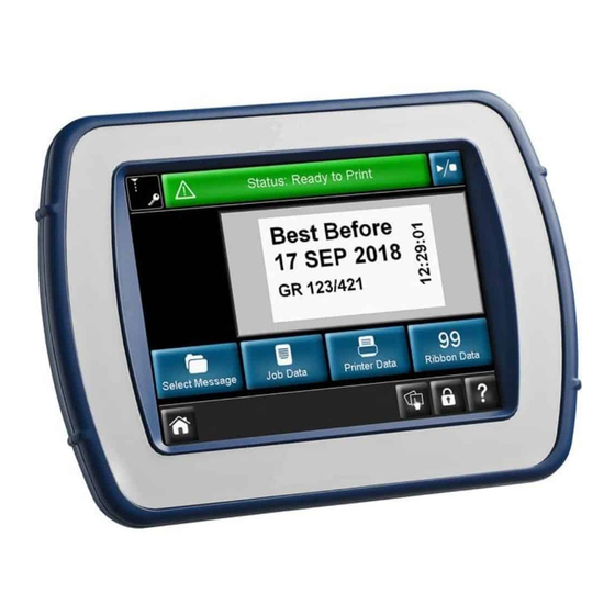
Page 45: Compact Touchscreen
Description and Installation Compact Touchscreen Note: The Compact Touchscreen is optional and might not be supplied with the printer. Stylus Rear View Compact Touch- USB A Mini-USB Ethernet screen LCD Panel Port Port Port Front View CAUTION: Due to limitations in the USBA connection, do not attach devices consuming power above 100mA to the USB port of the Compact Touchscreen. -
Page 46: Touchscreen
Description and Installation Touchscreen Notes: (1) The Touchscreen is optional and may not be supplied with the printer. (2) The printers have a powered Ethernet port. This can be used to power the Touchscreen without additional power cables. Contents Part No. Optional Touchscreen (with EPT007715 European mains lead and... -
Page 47: Touchscreen Rear View
Description and Installation Touchscreen Rear View Communication Mains Mains Mains Port Fuse Ports Switch Socket • Plug the crossover cable into the I/O box • Connect the mains cable to the Touchscreen • Connect the crossover cable to the Touchscreen •... -
Page 48: Threading The Ribbon
Description and Installation Threading the Ribbon WARNING: Care must be taken when replacing/threading ribbons to avoid cutting hands or fingers. Notes: (1) To ensure good quality print, always clean the print head and capstan before fitting a new ribbon to the printer. (2) When fitting a new ribbon, ensure loose ribbon is wound up on the take-up spool to create tension in the ribbon path. - Page 49 Description and Installation (4) The printer will be set up as either a right-hand printer or a left-hand printer. Referring to the ribbon path diagram labels on the printer cover or in the following diagrams, determine whether the printer is set up for left-hand or right-hand printing and thread the ribbon accordingly.
-
Page 50: Set Up Printer - Final Steps
Description and Installation Set Up Printer - Final Steps CAUTIONS: The printer must be calibrated before installing it on the production line. See below. In dusty environments, it may be beneficial to fit a Positive Air Kit (P/N EAS002970). Calibrating the Printer CAUTION: When calibrating, the print head must be able to extend fully, please ensure enough space is allowed... -
Page 51: Optimising The Print Head
Description and Installation Optimising the Print Head Having mechanically installed the printer in the brackets, optimise the head position for printing: (1) Go to Settings > Production Line Setup > Line Movement. Either CM (Moving) or IM (Static) will be displayed in the Line Movement pull-down menu. - Page 52 Description and Installation Peel-off Print head Roller Ribbon Guide Roller Platen Bracket Mounting - Intermittent Mode (IM) (4) Set the Print Trigger as required at Settings > Production Line Setup > Print Trigger. For more information, see “Print Trigger” on page 3-48. (5) Go to Settings >...
-
Page 53: Test Print And Calibrate
Description and Installation Test Print and Calibrate Go to Settings > Production Line Setup > Head Functions and select the desired function. For further information, see “Head Functions” on page 3-50. Speed Profile The Speed Profile function allows instantaneous display of the print trigger signal alongside the substrate speed and the ribbon speed. -
Page 54: Cm Speed Profile Graph
Description and Installation CM Speed Profile Graph Substrate speed Ribbon Speed Printing Print Go It may be necessary to scroll up/down and left/right to see the full graph. Press Refresh to repeat the capture. 2-38 EPT033612 Issue 2 March 2018... -
Page 55: Im Speed Profile Graph
Description and Installation IM Speed Profile Graph Printhead speed Ribbon Speed Printing Print Go It may be necessary to scroll up/down and left/right to see the full graph. Press Refresh to repeat the capture. EPT033612 Issue 2 March 2018 2-39... -
Page 56: User Interface Settings
Description and Installation User Interface Settings User Interface Settings are used to define the Compact Touchscreen / Touchscreen settings and connectivity to printers. Unlock User Interface Settings User interface settings are password protected to prevent accidental changes. To unlock the user interface settings whilst the user interface is connected to the printer follow the procedure from step (1). -
Page 57: Network
Description and Installation Network Set up the network settings for the Compact Touchscreen / Touchscreen. The IP address of the device can be changed manually or automatically. When connected to a network, always manually assign one IP address to the printer and another IP address to the Compact Touchscreen. While automatic assignment of IP addresses may seem simpler, some complications are associated with this approach. -
Page 58: Locating The Printer's Ip Address When Not Known
Description and Installation Locating the Printer’s IP Address when Not Known Requirements • Computer with Microsoft ActiveSync for Windows XP or Mobile Device Center for Windows Vista or Windows 7 (version 4.1 or higher). ActiveSync can be downloaded from Microsoft homepage •... -
Page 59: Use Of Usb To Find Out Which Ip The Printer Is Using
Description and Installation • Windows Mobile Device Center (or ActiveSync in Windows XP) should now activate: • To explore the device, select Explore. If the program does not start, remove the mini USB cable and reinsert it. Use of USB to Find Out which IP the Printer is Using (1) Navigate to the root folder of the device. -
Page 60: Changing The Compact Touchscreen / Touchscreen Ip Address
Description and Installation (4) Save the file. (5) Copy the file back onto the device in the ‘\Flash Disk’. (6) Remove USB cable and reboot printer. Changing the Compact Touchscreen / Touchscreen IP Address Note: User interface settings must be unlocked before starting this procedure see “Unlock User Interface Settings”... -
Page 61: Adding More Connections
Description and Installation Adding More Connections To add a new printer to the network or if an existing printer has been assigned a new IP address follow the procedure bellow. Note: User interface settings must be unlocked before starting this procedure see “Unlock User Interface Settings”... -
Page 62: Touchscreen
Description and Installation Touchscreen (1) Ensure that the printer is tuned on and attached to the network. (2) Ensure that the Touchscreen is not connected to any printers. (3) Select Settings > Printer Connection > Connection Method and choose one of the following options. Broadcast: Select Broadcast to display a list of detected devices on the network. -
Page 63: Usb Connection Setup (Printer And Compact Touchscreen Only)
Description and Installation USB Connection Setup (Printer and Compact Touchscreen only) Note: User interface settings must be unlocked before starting this procedure see “Unlock User Interface Settings” on page 2-40. To connect to a printer with a Compact Touchscreen via USB follow the procedure bellow. -
Page 64: Advanced Settings
Description and Installation ADVANCED SETTINGS System Variable • Machine ID - Use this setting to assign a name to the printer. It is this name that defines the machine ID (identity), which can be used as a variable in a message Note: Do not confuse the machine ID with the host name. -
Page 65: Install Options
Description and Installation Install Options • Hotstart - When the system is switched on, the Hotstart function (if enabled) automatically tries to load the design that was loaded when the system was last switched off Note: Any counters and real time variables in the design are re-initialised as they would be during a normal job load. - Page 66 Description and Installation THIS PAGE INTENTIONALLY LEFT BLANK 2-50 EPT033612 Issue 2 March 2018...
- Page 67 PART 3 : Operation CONTENTS Page START-UP ..................... HOME SCREENS MENUS..............SCREEN FUNCTIONS................General..................... Editor Screen ................... SHUT DOWN ..................Disconnect Compact Touchscreen / Touchscreen from Printer ..Printer Shut Down................STATUS BAR..................MESSAGES ................... NEW MESSAGE ..................3-10 Add....................3-10 Text.....................
- Page 68 Operation ADJUSTING PRINTING PARAMETERS..........3-34 Global Print Settings ............... 3-34 Quality..................3-34 Economy..................3-36 Position ..................3-39 Technical ................... 3-41 Print Counter ................3-43 Saved With Message ..............3-43 ALERT CONFIGURATION..............3-44 Configure Alerts................3-44 Ranged Alerts.................. 3-45 Error and Ready Signals..............3-45 PRINTER SETUP ..................
- Page 69 Operation SD EMULATOR ..................3-56 Unsupported Functions.............. 3-56 Enable the SD Emulator ............. 3-57 Connect to the Printer Using CoLOS Create ......3-57 Use Messages Designed for SD 5, X40 or X60......3-58 Download a File to the Printer ............ 3-58 Request a Message at the Printer ..........
- Page 70 Operation THIS PAGE INTENTIONALLY LEFT BLANK EPT033612 Issue 2 March 2018...
-
Page 71: Start-Up
Operation START-UP With the printer connected to the power supply and the mains, see “Connectivity” on page 2-21, select the Power / Reset button on the front of the printer. The printer can be operated via a Compact Touchscreen, Touchscreen, PC or laptop. -
Page 72: Home Screens Menus
Operation HOME SCREENS MENUS The default Home Screen Menus are Messages, Printer Status, Global Print Settings and Settings, as shown below: Home Screen Menus Long-press to Access Security Management It is possible to configure the third button (‘Global Print Settings’ in the example above): •... -
Page 73: Screen Functions
Operation SCREEN FUNCTIONS General Status Icons Screen Play / Stop Title Button (when activated*) Tabs Alert / Status Bar Scroll By: Line Page Lock Screen / Breadcrumb Main Log Off / Trail Screen Area Disconnect (Navigation) from Printer * For more information, see “Status Bar”... -
Page 74: Shut Down
Operation SHUT DOWN Disconnect Compact Touchscreen / Touchscreen from Printer • If you are at the Log In screen, select Disconnect OR • From any other screen, select and then select Disconnect from printer. • If a Compact Touchscreen is being used, it will turn off when its power is removed. -
Page 75: Messages
Operation MESSAGES Selecting the Messages button will open the messages screen: Message Store In the screen above, the message store called Internal and a list of messages it contains are displayed. Select any saved message from within a message store or from the list of messages. You can then edit, preview, cancel or send the message to print. -
Page 76: New Message
Operation NEW MESSAGE Select Messages > New Message to open the Message Editor - note that for new messages, the default menu will be Add: Undo/Redo Add Menu Notes: (1) The Undo/Redo buttons can be used at any stage of the message creation or editing process to undo or redo the previous action. -
Page 77: Text
Operation Text To enter text into the message, select the Add Text icon. Enter the required text using the keyboard. Move Text Area Cursor within Text Area Clear the Text Field Delete Previous Shift, Character Unicode and IME Buttons Select to Alternative Display Keyboard... - Page 78 Operation Unicode characters can be entered by selecting the Unicode button (the button will change to amber). Enter the Unicode value - the responding character (and value) will be displayed in the top right of the screen: Unicode Value Unicode Character Text Area Select...
-
Page 79: Variable
Operation Variable Variables such as clocks, counters, prompts, links, etc. can be included in the message. Select the button and select +Create New... to display a list of new variables that can be created. Clock Create a new clock variable - enter any offsets required. The following properties are available for editing: Format: Click the format field to display a list of possible clock formats. - Page 80 Operation Supported Time Formats Value Description Hours with no leading zero for single-digit hours; 12-hour clock Hours with leading zero for single-digit hours; 12-hour clock Hours with no leading zero for single-digit hours; 24-hour clock Hours with leading zero for single-digit hours; 24-hour clock Minutes with no leading zero for single-digit minutes Minutes with leading zero for single-digit minutes Seconds with no leading zero for single-digit seconds...
- Page 81 Operation Offset Policy: If a clock is required showing a later (or earlier) date than the current one, an offset may be applied. The time which will be printed is then the current time plus (or minus) the offset. The value of the offset can be set in three ways: Fixed offset A defined offset is applied.
- Page 82 Operation Truncate Date is only active for offsets with months and years. The different types of offset are applied in the following order: Year Month Week, Day, Hours and Minutes. Example: Current day = 31.01.2013, plus 1 month = 31.02.2013 Truncate Day active: Since 31.02.2013 is an invalid date, it is truncated to Date: 28.02.2013...
- Page 83 Operation This way an entire week’s production that is made on a single day can be simulated. • Update Day: The update day can be set. • Update Hour: The update hour can be set. • Update Minute: The update minute can be set. Example: Actual day: Monday the 15 Apr 2013...
-
Page 84: Counter
Operation Counter Create a new counter variable. This will increment/decrement according to the parameters set. The following properties are available for editing: Fixed Start Check this box for the counter to start at the value set in the Value property. If this box is not checked, the user will be prompted to enter a start value. -
Page 85: Prompted Field
Operation Resume Check this box and the counter will resume from the last printed number. Roll Over Check this box to set a minimum and maximum range for the counter. Example: If the minimum value is 0 and the maximum value is 5 the sequence would be: “0,1,2,3,4,5,0,1,2,3,4,5,0,1,2,3,4,5..”... -
Page 86: External Data
Operation External Data This menu is used to set up data transmission of variables from an external PC to the printer. The following properties are available for editing: Default Text: Once the Use Default check box has been ticked, the user can then enter any value. - Page 87 Operation Explanation: \x01 (SOH = Hex 01) FillSerialVar= (Must make an exact match) \x02 (STX = Hex 02) Serial (We assume that this particular variable is called “Serial”.) \x03 (ETX = Hex 03) (Must make an exact match) \x02 (STX = Hex 02) \v06 (The input data is exactly (Hexadecimal)6 characters) \x03 (ETX = Hex 03) \x17 (ETB = Hex 17)
- Page 88 Operation Name: The name of the variable is entered here. Selecting the name field will call up a keyboard where the user simply enters in the desired name and selects OK. Note: No two variables can have the same name. If the name of an already used variable is changed, the items in which the variable is used must be manually updated.
-
Page 89: Printer Data
Operation Printer Data Add the Printer ID or User ID to the message. Shift Code Create or edit shift code data within the message. The following properties are available for editing: Name: The name of the variable is entered here. Selecting the name field will call up a keyboard where the user simply enters in the desired name and selects OK. -
Page 90: Barcode
Operation Barcode Select the Add Barcode button, type the name of the message and select button. Select the More button. On the barcode’s list of Properties, enter the barcode data as appropriate, then select the button to insert the code into the message. To display / edit properties, either: •... - Page 91 Operation The following barcode properties are available for editing: Height (mm): This allows the height of the barcode to be indicated. Note: This is not applicable for all types of barcodes. Numerical values can be entered. Bold: The barcode can be formatted in bold. Invert: Selecting Invert will convert the black lines of the barcode to spaces, and the gaps between the original black lines of the barcode will be...
- Page 92 Operation Show Human Readable Code: To show the values contained in the barcodes, this box should be active. The human readable interpretation will be printed under the actual barcode. Human readable interpretation for the 2D composite component will be printed above the code (one application identifier per line). Invert: Select the checkbox to invert the barcode.
-
Page 93: Shape
Operation Shape To insert a shape into the message, select the Shape button from the Add menu, select the required shape from the list. A properties box will open, define the properties of the shape and select the button to insert into the message. Using the Move/Size and Rotate/Flip functions, arrange the item as... -
Page 94: Move/Size
Operation Move/Size Once an item has been added to the message, select the Move /Size Menu to move or resize the item within the message field. To move an item in the message: • Select the desired item within the message, then, using the directional Move arrows, move the item as required, or, •... -
Page 95: Zoom
Operation Zoom Select the Zoom Menu to change the magnification of the message area. Use the Zoom Toolbar: To view the item(s) in the Message field or the whole Message field in a different size, select the item(s) and then select the appropriate button from the above toolbar: (1) Incrementally zoom in on the message area (2) Incrementally zoom out of the message area... -
Page 96: File
Operation File At the File Menu screen, the user can select from the following Message Options: (1) Create new message (2) Save message (3) Save as a new message (4) Add new Shift Code table (5) View/edit variable properties (6) View/edit the message properties (7) Delete item from message (8) Send to print Save Message... -
Page 97: Selecting An Existing Message
Operation SELECTING AN EXISTING MESSAGE Where no message is selected, no message will be displayed in the Home screen: Selecting the Messages button will open the Message Store or stores. Select the required store and then the required message from the list. The following screen will display: Choose to Edit, Preview, Send to Print or Cancel. - Page 98 Operation (3) Select Edit. (4) The message will then open in the Message Editor, note that the Edit toolbar is open. Note: Long-press an item within the message to open its properties menu. (5) The message can now be edited, using any of the following edit functions: (10) (11)
- Page 99 Operation To edit the content within an item, select the item and select the More button. The following screen will display: Note: The above screen will differ slightly for Barcode items. The Properties area will be open as default. Dimensions and location details can be changed, as well as rotation, font and italicisation.
-
Page 100: Adjusting Printing Parameters
Operation ADJUSTING PRINTING PARAMETERS Global Print Settings This sets the print settings for new messages and any parameters that are not saved with the messages. To adjust the print settings, go to Settings > Global Print Settings: Quality The Quality menu allows the alteration of those parameters that will normally affect print quality. - Page 101 Operation Preheat The preheat settings increase the contrast on the leading edge of the print, which can be useful when printing in a cold environment. Slope Type (CM only) Controls the acceleration and deceleration of the ribbon motor. The acceleration and deceleration is determined by the speed of the web.
-
Page 102: Economy
Operation Economy The Economy menu enables the definition of some of the parameters that have a direct cost savings effect for the print run. All the values entered in this menu will therefore influence the consumption of ink ribbon. Ribbon Economy This feature uses the FADING technique, which is one of the printer's patented features. - Page 103 Operation Retraction Type (CM only) This setting is very important in reducing consumption of ribbon. The thermal transfer printer normally works at very high speeds, and in many cases the ribbon will be pulled a few millimetres too far with a resultant waste of ribbon.
- Page 104 Operation Column Mode Ribbon Economy Column Mode Ribbon Economy can be used with both IM and CM printers. When using Column Mode, the printer retracts the ribbon after each print, allowing the next print to be made next to the previous one on the used ribbon.
-
Page 105: Position
Operation Column Mode is set up by varying the Number of Columns and Column Width parameters, as follows: • Number of Columns: This is the number of columns into which the user wants to divide the ribbon width into (five columns in the preceding example). - Page 106 Operation Start Pulse Offset There may be reasons to displace the print in the Y direction, but such a displacement is prevented by printing starting in the middle of the packaging machine signal. If this occurs, an error or warning will be displayed on the screen and the machine will only print every other print.
-
Page 107: Technical
Operation Head Position Offset This option adjusts the horizontal position of the print head. Set the value at Production Line Setup > Print Head > Head Position Offset. Mirror / Flip Message Both the Mirror and Flip Message features produce a mirror image of the print and may be used to advantage when printing on the inside of transparent material. - Page 108 Operation Head up When the print head must be raised, i.e. at the end of a print, the printer's software sends a signal to a motor, thus raising the print head. There is normally a delay whilst the head is physically raised, to compensate for this delay, the Head Up value can be increased, thus causing the signal to be transmitted earlier.
-
Page 109: Print Counter
Operation Print Counter During message selection, the Print Counter prompts the user to enter a number of prints to be printed. For example, if you have selected that 100 labels are printed, once printing is complete you will be prompted to select the next action. -
Page 110: Alert Configuration
Operation ALERT CONFIGURATION Configure Alerts Go to Settings > Alert Configuration to configure errors / warnings: Note: The screen above shows configurable alerts for IM printers. There are more alert configuration options for CM printers. It is possible to change the alert level for some alerts. In the above example, the Ribbon Error is currently a Warning. -
Page 111: Ranged Alerts
Operation Y-offset (Head and Motor): If the distance between the label start and the first line is too short, a warning or error signal will be displayed on the screen. If the Y-offset is too short, the print head cannot print the first pixels and hence the print may not comply with the desired quality standards. -
Page 112: Printer Setup
Operation PRINTER SETUP Production Line Setup To add a printer to a production line or change the setup, select Production Line Setup. If the Home screen buttons are not set to default, the Production Line Setup can be found at: Settings > Production Line Setup. Line Movement Set details of the Production Line: Whether the substrate / printer are Continuous Mode (CM) or Intermittent... - Page 113 Operation Line Movement - IM (Static) EPT033612 Issue 2 March 2018 3-47...
-
Page 114: Print Trigger
Operation Print Trigger This menu changes for CM printers and for IM printers. Set details of how printing is triggered: (1) Trigger By: (a) For CM printers, from the pull-down menu, select the source for the print trigger - External Input, Internal (Distance) (which prints continuously while the print trigger is closed) or Internal Continuous (which prints continuously while a valid message is selected and there are no errors or warnings active). -
Page 115: Print Head
Operation Print Head CAUTION: The printer must be calibrated before installing it on the production line. Go to Settings > Production Line Setup > Head Functions and select Calibrate. When calibrating, the print head must be able to extend fully, please ensure enough space is allowed to perform this function. -
Page 116: Head Position Offset
Operation Head Position Offset This option adjusts the horizontal position of the print head. Note: This value must be set to zero at install and at any time that the Align function on the printer is used. The offset can also be saved in each message, allowing a degree of adjustment when the message is loaded. -
Page 117: Inputs/Outputs
Operation Inputs/Outputs Assignment This tab shows the pin, input and output assignments. Pull-down menus accompany each assignment. For a detailed pin allocation table, see page 2-12 page 2-13. For a table of functions / behaviours for each output, see page 2-18. -
Page 118: Regional Settings
Operation Regional Settings To change the UI Language or Keyboard layout, go to the following: Settings > Regional: Language and Keyboard From this tab, the user can access pull-down menus to select the printer’s defaults for the following: Language, Keyboard Layout, IME Scheme and Primary Currency. -
Page 119: File Manager
Operation FILE MANAGER This menu allows the user to add new stores and manage existing Local and Printer directories and files. To access the File Manager, go to Settings > File Manager. Printer From this directory, the user can access files and directories that reside on the printer. -
Page 120: Security Management
Operation SECURITY MANAGEMENT Security management allows users and groups to be setup and access levels set accordingly. To access the Security Management menu, from the Home Screen long-press the user / printer ID area or go to Settings > Security: Setup This screen configures the printer’s Auto Log in feature. -
Page 121: Groups
Operation Groups Create and manage groups - this will allow the access level to be set for each group. For example, Operators can be set such that they can only select and send messages to print, whereas the Operator Supervisor could be created and set such that they can create and manage messages. -
Page 122: Sd Emulator
Operation SD EMULATOR The SD Emulator is a special feature which allows the printer to print messages that have been created using CoLOS. It also allows messages to be saved on the printer converting them into EasyDesign format. Unsupported Functions The emulator provides most common functionality, however the following functions are not supported: Font Matching. -
Page 123: Enable The Sd Emulator
Enable the SD Emulator The SD Emulator must be enabled with a feature code before it can be used. A feature code can be obtained from Easyprint by contacting the technical help desk and providing the system ID of each printer. -
Page 124: Use Messages Designed For Sd 5, X40 Or X60
Operation Use Messages Designed for SD 5, X40 or X60 Messages designed for SD 5, X40 or X60 machines have some different functionality, but when being used with CoLOS Create they can be loaded and sent to an SD 3 printer and CoLOS will convert the features as needed. Alternatively the message can be permanently converted in CoLOS Create by loading the message and selecting File >... -
Page 125: Allocating A Job Source To A Printer
Operation Allocating a Job Source to a Printer (1) In CoLOS Control right click the printer to be changed and select Properties. (2) Select Job Sources > Configuration > Browse, this will display a list of available job sources. (3) Select Default Job Source (or as applicable), then select OK. (4) The device properties will now show the selected job source. - Page 126 Operation THIS PAGE INTENTIONALLY LEFT BLANK 3-60 EPT033612 Issue 2 March 2018...
- Page 127 PART 4 : Maintenance, Service and Fault Finding CONTENTS Page PREVENTATIVE MAINTENANCE ............Front Cover Sensor................Ignore Cover Sensor ..............Rear Cover ..................Vertical Print Head Calibration............Maintenance Schedule ..............Cleaning The Print Head ..............REPLACING THE PRINT HEAD............. Head Resistance................REPLACING THE PRINT HEAD ACTUATOR ........
- Page 128 Maintenance, Service and Fault Finding TROUBLESHOOTING GUIDE............... 4-47 Print Problems................. 4-47 Print Quality and Print Head............4-50 Network ................... 4-58 Printer ....................4-58 Ribbon Breaks................. 4-59 EPT033612 Issue 2 March 2018...
- Page 129 Maintenance, Service and Fault Finding EPT033612 Issue 2 March 2018...
- Page 130 Maintenance, Service and Fault Finding THIS PAGE INTENTIONALLY LEFT BLANK EPT033612 Issue 2 March 2018...
-
Page 131: Preventative Maintenance
Maintenance, Service and Fault Finding PREVENTATIVE MAINTENANCE Front Cover Sensor The printer is fitted with a front cover to protect the internal mechanism of the printer from dust. During normal use, the cover should be fitted at all times to ensure that the mechanism is protected. A sensor within the printer detects if the cover is fitted. -
Page 132: Maintenance Schedule
Maintenance, Service and Fault Finding Maintenance Schedule The printer does not require component replacement as part of a preventative maintenance routine. We recommend regular checks to ensure optimum performance is maintained and to allow any parts requiring future replacement to be identified early. Frequency Recommended Actions Regularly... -
Page 133: Cleaning The Print Head
Maintenance, Service and Fault Finding Cleaning The Print Head Note: Always clean the print head after replacing it or a ribbon. Some of the dots on the print head can get damaged during use. Overheated dots can result in disintegration of the ceramic material as shown in the picture on the left. -
Page 134: Replacing The Print Head
Maintenance, Service and Fault Finding REPLACING THE PRINT HEAD Notes: (1) This procedure is applicable for all printer variants, although the 32mm print head appears in the following photographs. (2) Tool required: 2.5mm Allen key. WARNING: Ensure printer is switched off and disconnected from the power supply before following this procedure. -
Page 135: Head Resistance
Maintenance, Service and Fault Finding Slide the old print head out. Record the new print head resistance value. Slide in the new print head assembly and fit a new retaining clip. Fit the head cable back into the connector and gently close the connector. -
Page 136: Replacing The Print Head Actuator
Maintenance, Service and Fault Finding REPLACING THE PRINT HEAD ACTUATOR Notes: (1) The print head actuator is supplied without the print head and print head adaptor board. (2) Tools required: Flat-head screwdriver, Threadlocker (medium strength), 2.5mm and 3mm Allen keys, TX20 Torx driver, 5.5mm nut spinner, long-nosed pliers. -
Page 137: Align Small Stepper Motor Gears
Maintenance, Service and Fault Finding Align Small Stepper Motor Gears Fitting the small stepper motor gears onto the plastic side arm teeth is crucial to proper printer operation. Perform this procedure after changing either: • Any parts of the print head actuator mechanism OR •... -
Page 138: Adjusting The Print Head Angle
Maintenance, Service and Fault Finding (3) Lift the stepper motor and position the gears so that the plastic side arm teeth are even on both sides of the stepper motor, as shown in the following photo: (4) Hold the stepper motor in place and retighten the four screws. (5) Refit the printer back cover and print head. -
Page 139: Replacing The Capstan Roller
Maintenance, Service and Fault Finding REPLACING THE CAPSTAN ROLLER Note: Tools required: 2mm Allen key To replace the capstan roller: (1) Turn the grub screw behind the capstan anti-clockwise. Grub Capstan Screw Roller Printer (2) Pull the capstan roller assembly out. (3) Fit the new capstan roller onto the motor shaft. -
Page 140: Changing The Drive Belt
Maintenance, Service and Fault Finding CHANGING THE DRIVE BELT Note: Tools required: 2.5mm Allen key. (1) Remove the bridge cover. Bridge Cover (2) Remove the actuator assembly, as described in “Replacing the Print Head Actuator” on page 4-10. 4-14 EPT033612 Issue 2 March 2018... - Page 141 Maintenance, Service and Fault Finding (3) Lift the print head mounting arm to expose the two screws. Belt Clamp Screws (4) Loosen the two belt clamp screws. (5) Remove the belt. (6) Fit the new belt. (7) Tighten the belt clamp screws. (8) Refit the actuator assembly onto the printer.
-
Page 142: Changing Printer Configuration
Maintenance, Service and Fault Finding CHANGING PRINTER CONFIGURATION This procedure details how to change a right-handed printer set-up to a left-handed printer set-up or vice versa. Notes: (1) Parts required for non-cassette printer: EDP003942 Rehanding Ribbon Path Labels (10 LH and 10 RH) (2) Parts required for cassette printer: EDP003941 Rehanding Ribbon Path Labels (10 LH and 10 RH) (3) Tools required: 2.5, 3mm and 4mm Allen keys, 5mm spanner,... - Page 143 Maintenance, Service and Fault Finding (10) Remove the back cover. (11) At the back of the printer, disconnect the IM stepper motor and the capstan stepper motor. CAUTION: When unplugging the stepper motor connectors from the PCB set, fully press the clip on the inner part of the connector before pulling it out (see the following photograph).
- Page 144 Maintenance, Service and Fault Finding (13) Adjust the ribbon tension. Ribbon tension is controlled by springs fitted to each of the two dancing arms. Dancing arm springs can be fitted in a number of defined positions, allowing the spring force and ribbon tension to be varied if required - see the next photograph.
- Page 145 Maintenance, Service and Fault Finding Changing from Default Dancing Arm Spring Positions Dancing arm spring positions may need to be changed from the default positions in the following conditions only: • If using 22mm wide R1 Grade ribbon, the ribbon tension must be reduced by changing the rewind dancing arm spring to position 6 and the unwind dancing arm spring to position 4.
-
Page 146: Back-Up & Restore
Maintenance, Service and Fault Finding BACK-UP & RESTORE Go to Settings > Backup & Restore: Backup On the Backup tab screen: (1) Review and note the list of back-up types that are required. (2) Go to Settings > Security > Electronic Signature and view / edit / add Electronic Signatures so that the list matches that of the desired back-up types. -
Page 147: Restore
Maintenance, Service and Fault Finding Restore The Restore tab screen follows: From the Restore tab: • Select the Source • Select an available Restore Type and select the Restore button. Update From the Update tab, if updates are found on this screen, you can manually restart the update. -
Page 148: Fault Finding
Maintenance, Service and Fault Finding FAULT FINDING Front Cover Sensor “Front Cover Sensor” on page 4-5. Sensor Test Note: To test the sensors, the printer needs to be connected to the Power Supply Unit (PSU) and the unit switched on. When you are ready to perform the test, see “Sensor Test Procedure”... -
Page 149: Sensor Test Procedure
Maintenance, Service and Fault Finding Sensor Test Procedure To access the menu that assists in testing the printer, select Settings > IO Port > Monitor. The following screen will display: Scroll down to Sensor and observe the display readings obtained. Note: All sensors are Hall Effect devices. - Page 150 Maintenance, Service and Fault Finding Home ‘Sensors’ - To test the home sensor, move the print head carrier (sledge) ‘horizontally’ slowly and gently from one side to the other while observing the sensor readings on the screen. Print Head assembly (Sledge) “Home Sensor (Left, Middle and Right)”...
-
Page 151: Io Test
Maintenance, Service and Fault Finding IO Test Select Settings > IO Port > Test. The following screen appears: Select Test Mode to check the input / output settings to ensure that they are wired correctly. EPT033612 Issue 2 March 2018 4-25... -
Page 152: Printer Led Status
Maintenance, Service and Fault Finding Printer LED Status The LED indicator on the printer is used to indicate the various states of the printer. The indicator is on the front of the printer. Printer Status LED Colour Idle Blue Ready Green Printer Open Printing... -
Page 153: Errors / Warnings
Maintenance, Service and Fault Finding ERRORS / WARNINGS “Alert Configuration” on page 3-44. List Of Errors Use this list for quick troubleshooting problems with the printer. Note: All error codes in the following list can trigger an error signal EXCEPT for the ones in Error/Warning settings that have been set to Warning or Ignore. - Page 154 Check for shorts in the cable that end in the print head itself. DO NOT REPLACE ANY PARTS - call for qualified Easyprint personnel or contact the supplier. Init: Main power The voltage supplied by the external supply power supply is tested during start.
- Page 155 Maintenance, Service and Fault Finding Error No. Error Text Action Start when printer not The printer has received a start signal ready while printing. Reduce speed or increase distance between start signals. No acknowledge on Communication error between start pulse controller and print unit.
- Page 156 Maintenance, Service and Fault Finding Error No. Error Text Action 1004 Step programming Contact service technician. cancelled 1005 Main FPGA not Contact service technician. started 1006 Main FPGA still not Contact service technician. loaded 1007 Main FPGA not Contact service technician. loaded 1008 Step driver...
- Page 157 Maintenance, Service and Fault Finding Error No. Error Text Action 1019 Calibration required CAUTIONS: (1) When calibrating, the print head must be able to extend fully, ensure enough space is allowed to perform this function. For CM printers: The print head position parameter must be set to allow this.
- Page 158 Maintenance, Service and Fault Finding Error No. Error Text Action 1047 Upgrade Failed Upgrade failed. Check the Software Versions screen. 1048 Special Action Not Error in firmware/software. Contact Found: supplier and supply information on how the error occurred. 1049 CRC Error All files on the controller have a CRC checksum.
- Page 159 Maintenance, Service and Fault Finding Error No. Error Text Action 1061 No external flash Some operations require an external detected flash card. No external flash card is detected. Abort the operation. If required insert a Compact Flash Card while the power is switched off. 1062 Error Writing File Error while writing a file to disk.
- Page 160 Maintenance, Service and Fault Finding Error No. Error Text Action 1079 Recursive log write, Error in firmware. Contact supplier and log disabled supply information on how the error occurred. 1080 Image not found The image could not be found. Check the filename (If design is saved on network by EasyDesign check the Save to SRAM field).
- Page 161 Maintenance, Service and Fault Finding Error No. Error Text Action 1102 Invalid Value The typed in value could not be interpreted. 1103 Too many characters More characters have been typed in than are specified by the variable. Type in fewer characters, or modify the design to accept more characters.
- Page 162 Maintenance, Service and Fault Finding Error No. Error Text Action 1113 Illegal compare A variable is compared to another variable using an unrecognised compare operator. Use one of the following compare operators: =, ==, !=, >=, <=, < or >. 1114 Label Missing Check the goto command.
- Page 163 Maintenance, Service and Fault Finding Error No. Error Text Action 1126 Illegal compare for Use single or double equal (= or ==) to strings test if two strings are equal. Use exclamation mark equal (!=) to test if two strings are different. 1127 Can't compare string A string can’t be compared to a...
- Page 164 Maintenance, Service and Fault Finding Error No. Error Text Action 1137 String Value overflow The maximum length of a string variable is 0x7FFF (32767) characters. Check the macro. There may be a programming error that causes the string’s maximum length to be exceeded.
- Page 165 Maintenance, Service and Fault Finding Error No. Error Text Action 1172 CodePage file not The codepage specified by the variable found could not be found. Please check the codepage selection. 1173 Interrupt Not A part of the printing software was not Initialised started correctly.
- Page 166 Maintenance, Service and Fault Finding Error No. Error Text Action 1229 Unable to print. On a 21 CFR - Part 11 compliant System log failed system, printing cannot start if the system log fails. Check free space. 1230 Invalid anchor point The anchor point setting could not be set.
- Page 167 Maintenance, Service and Fault Finding Error No. Error Text Action 1266 Network busy. Try later. 1267 Network connection Cancel was selected before the was cancelled. connection was established. 1268 Device is already The network connection is already remembered. established. 1269 The specified password is invalid.
- Page 168 Maintenance, Service and Fault Finding Error No. Error Text Action 1293 Disconnection Failed Try again. 1294 Error Disable Network Switch off unit Thread 1400 Windows Socket Init Could not initialise networking features. Failed Reboot unit. 1401 Unknown Error Unknown protocol error. 1402 Unknown Receive Id The information received was not recognised.
- Page 169 Maintenance, Service and Fault Finding Error No. Error Text Action 1414 Error Reading Double A floating point number was supposedly sent but the receiver could not recognise the format. Check transmission. Lower the baud rate. Enable Hardware handshake. 1415 Error Reading data A block of raw data was supposedly sent but the receiver could not recognise the format.
- Page 170 Maintenance, Service and Fault Finding Error No. Error Text Action 1431 Unable to start listen Reboot unit. thread 1432 Error terminating Reboot unit. listen thread 1433 Unable to accept Not used socket 1434 Printer protocol is too Check versions. Upgrade unit if required.
- Page 171 Maintenance, Service and Fault Finding Error No. Error Text Action 1603 Could not load file Could not extract the file information information from the archive. Check for valid upgrade file. 1604 Could not read Could not extract the service pack service pack information from the archive.
- Page 172 Maintenance, Service and Fault Finding Error No. Error Text Action 1618 Unsupported version The software in the unit did not meet the requirements for the upgrade. Check which version is installed, and which version is required by the upgrade file. 1619 Failed reading CFR21 Could not determine if the upgrade...
-
Page 173: Troubleshooting Guide
Maintenance, Service and Fault Finding TROUBLESHOOTING GUIDE Print Problems When poor print quality occurs, check the following list to ensure that settings/conditions are correct: Setting/Condition to Check Setting/ Setting/ Condition: Condition: IM Printers Printers Is the printer in ‘Ready’ mode and able to print? ... - Page 174 Maintenance, Service and Fault Finding Setting/Condition to Check Setting/ Setting/ Condition: Condition: IM Printers Printers Is the dwell time sufficient for the amount of print required? Is the parent machine giving the printer a print signal? Is there too much / not enough start pulse offset? Is the substrate still moving when printing?
- Page 175 Maintenance, Service and Fault Finding Setting/Condition to Check Setting/ Setting/ Condition: Condition: IM Printers Printers Is the print head heater being used and set appropriately (that is, 30° for cold environments)? Is the peel-off roller in the correct position, parallel to head and clean? ...
-
Page 176: Print Quality And Print Head
Maintenance, Service and Fault Finding Print Quality and Print Head Problem Action No Information is Printed If the printer appears to be operating correctly but no data is printed, check the following: Is a valid message selected? Check the print speed and contrast values are at appropriate levels for the thermal ribbon and substrate. - Page 177 The matching of the ribbon and the substrate is very important. An incorrect match will not give good print quality. Contact your local Easyprint distributor for further details. If lines of dots are not printing and cleaning the print head and platen / roller does not resolve the problem, replace the print head.
- Page 178 Maintenance, Service and Fault Finding Problem Action Faded print Print quality is dependent on the following: Quality of the substrate and ribbon being used, print contrast, print speed combination and the condition of the machine being used to print. The age and storage conditions of the ribbon can also affect the print quality.
- Page 179 If this is the case, use another ribbon grade. Ask your local Easyprint distributor for ribbon advice. Print smudges Reduce the Contrast value setting to compensate for extra friction forces that are applied on the ribbon during printing.
- Page 180 Maintenance, Service and Fault Finding Problem Action Encoder Check that the encoder is rotating (CM printers only) freely. The CM printer, it will not print unless the encoder is moving. Check that the encoder signal is sending a signal back to the controller. Ribbon Drive Problems If the print contrast is too high or the print speed too low, the ribbon can be...
- Page 181 There is a mismatch between the ribbon and packaging material. This is a common error when using a ribbon other than a Easyprint ribbon. After changing a print head, an incorrect print head resistance value was input. When changing the print...
- Page 182 Maintenance, Service and Fault Finding Problem Action There is shading/smudging on Head down time is too long. Reduce the first part of print out this in Print Parameters until the front edge is clean. Should the smudging still appear, increase the Motor start offset step by step until a satisfying result is obtained.
- Page 183 Maintenance, Service and Fault Finding Problem Action The packaging machine is Incorrect connection of the print signal. signalling print go but nothing Check the colours in the I/O cable. happens There is no closed contact from the packaging machine on print signal. Check the packaging machine signal.
-
Page 184: Network
Problem Action Printer constantly shows Ribbon core has incorrect specification. ribbon error Use original Easyprint ribbon. Sensor arm may be defective. Verify the sensors using the sensor test located in the diagnostics menu. Print head does not move The print head motion is driven by the up and down stepper motor. -
Page 185: Ribbon Breaks
Maintenance, Service and Fault Finding Problem Action The print head carriage A stepper motor, drive belt and linear slide does not move are used to move the print head. If the head does not drive, check the following: The drive belt and drive pulleys. Are the stepper motor connections correct? Check the condition of the linear slide. - Page 186 Maintenance, Service and Fault Finding THIS PAGE INTENTIONALLY LEFT BLANK 4-60 EPT033612 Issue 2 March 2018...
- Page 187 PART 5 : Technical Reference CONTENTS Page SYSTEM SPECIFICATION..............Compact Touchscreen ..............Printer Specification................. Power Supply Unit ................Optional Touchscreen..............PRINTING DATA..................EPT033612 Issue 2 March 2018...
- Page 188 Technical Reference THIS PAGE INTENTIONALLY LEFT BLANK EPT033612 Issue 2 March 2018...
-
Page 189: System Specification
Technical Reference SYSTEM SPECIFICATION Compact Touchscreen Type 5.7 inch, full colour Compact Touchscreen (640x480 resolution), handheld, with docking station. Compact Touchscreen 170(W) x 127.9(H) x 33.7(D) Dimensions (mm) Weight (kg) 0.385kg Connectivity USB, Ethernet, (Mini USB for power / data connection to printer) Network Interface Ethernet 10/100 base TX... - Page 190 Fonts Most TrueType fonts Controller / hardware No dedicated controller required. interface options Hardware interface options: Easyprint Compact Touchscreen (via USB cable- hot swappable), Shared Compact Touchscreen (via Ethernet cable or network), PC-based interface (via Ethernet cable or network) Connectivity...
-
Page 191: Power Supply Unit
Technical Reference Power Supply Unit Dimensions: 135mm x 58mm x 35mm Weight: 0.5kg Rated Input Voltage 90-264V; 1.5A Range: Output Voltage: +24V d.c. Rated Output Power: 120W subject to de-rating Working Temperature: 0 to +50°C subject to de-rating Storage Temperature: -20°C to +85°C Optional Touchscreen Display... -
Page 192: Printing Data
Technical Reference PRINTING DATA Material PE - PP - PA - PET - paper, Tyvek™, cellophane, etc. Print resolution Normal mode: 12 x 12 dots / mm = 300 x 300 DPI Fast Mode: 6 x 12 dots / mm = 150 x 300 dpi TrueType Fonts Arial, Arial black, Arial Narrow, Comic Sans MS, Courier New, Gautami, Georgia, HYGothic Extra,... - Page 193 PART 6 : Glossary of Terms CONTENTS Page GLOSSARY OF TERMS ................ EPT033612 Issue 2 March 2018...
- Page 194 Glossary of Terms THIS PAGE INTENTIONALLY LEFT BLANK EPT033612 Issue 2 March 2018...
- Page 195 Glossary of Terms GLOSSARY OF TERMS Alphanumeric Letter or number characters. Attribute A characteristic or distinctive feature. Breadcrumb Trail A sequential set of icons that allows the user to view where they are, where they’ve been and how to return to previously visited areas. Column Mode Printer feature which retracts the ribbon after each Ribbon Economy...
- Page 196 Some functions change behaviour if they are initiated with a long- press. QuickStep Common user interface that will be used across Easyprint’s technologies. Range Information presented by the printer - the range between which the value should appear. Ribbon Economy Patented feature that enables user to select how much ribbon will be used for each print.
- Page 197 Glossary of Terms SVGA Super Video Graphics Array. A graphics display system for PCs that supports 800 x 600 resolution (480,000 pixels). SVGA can support a palette of 16 million colours, depending upon the amount of video memory installed in a system. Universal Serial Bus.
- Page 198 Glossary of Terms THIS PAGE INTENTIONALLY LEFT BLANK EPT033612 Issue 2 March 2018...
- Page 199 Easyprint CM & IM Product Manual Easyprint A/S has a policy of continuous product improvement, the Company therefore reserves the right to modify the specification contained within this document without notice. © Easyprint A/S 2018. All rights reserved. For additional documentation, including other available languages, either scan the QR code, or go to https://www.easy-print.com/downloads...
Need help?
Do you have a question about the Compact CM and is the answer not in the manual?
Questions and answers