Table of Contents
Advertisement
CODE: 11104038A -11104038C -11104038E-11104038L-11104038N-11104038P
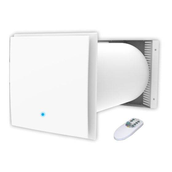
WALL-MOUNTED STATIC INTAKE-EXTRACTOR UNIT WITH HEAT RECOVERY
"PICO HP2 30 - HP2 55 - HP2 80"
CODE: 11104038H - 11104038R
WALL-MOUNTED CROSS FLOW STATIC INTAKE-EXTRACTOR UNIT WITH
HEAT RECOVERY "PICO RECO 100"
via dell'Industria 2/4 - Z.I. San Giacomo di Veglia 31029 Vittorio Veneto (Treviso), Italy
Tel/Phone +39 0438.500044 Fax +39 0438.501516
22
WWW.TECNOSYSTEMI.COM
USER MANUAL
Vers.05-28/01/2017
Advertisement
Table of Contents

Related Manuals for Tecnosystemi PICO HP2 55


Summary of Contents for Tecnosystemi PICO HP2 55
- Page 1 “PICO HP2 30 - HP2 55 - HP2 80” CODE: 11104038H - 11104038R WALL-MOUNTED CROSS FLOW STATIC INTAKE-EXTRACTOR UNIT WITH HEAT RECOVERY “PICO RECO 100” via dell’Industria 2/4 - Z.I. San Giacomo di Veglia 31029 Vittorio Veneto (Treviso), Italy Tel/Phone +39 0438.500044 Fax +39 0438.501516 WWW.TECNOSYSTEMI.COM...
-
Page 2: Safety Requirements
INTRODUCTION This manual includes the technical description, operation, installation and assembly instructions, technical data for the intake extractor unit with energy regeneration “PICO HP2”, “PICO RECO 100”, hereinafter referred to as recovery unit. SAFETY REQUIREMENTS Read the user manual carefully before use and installation of heat reversible recovery unit with individual chamber with energy regeneration. -
Page 3: Assembly Warnings
ASSEMBLY WARNINGS The recovery unit must not be used The recovery unit must be outside the temperature range, disconnected from the mains indicated in the user manual, supply before carrying out any or in aggressive or explosive installation or repair operation. atmospheres. - Page 4 EXTERNAL DIMENSIONS OF RECOVERY UNITS MOD. “HP2” DIMENSIONS (mm) EXTERNAL TUBE Ø CODE Ø 11104038L 11104038N 11104038P 11104038A 11104038C 11104038E TECHNICAL DATA OF RECOVERY UNITS MOD. “HP2” MODEL PICO HP2 - 30 PICO HP2 - 55 PICO HP2 - 80 SPEED POWER SUPPLY VOLTAGE 12 Vdc...
- Page 5 EXTERNAL DIMENSIONS OF RECOVERY UNIT MODEL DIMENSIONS (MM) “RECO 100” DIMENSIONS (mm) EXTERNAL TUBE Ø TECHNICAL DATA OF RECOVERY UNIT MOD. “RECO 100” SPEED MIN 1 AVG. 2 MAX. 3 POWER SUPPLY VOLTAGE 12Vdc POWER (W) MAX. CURRENT CONSUMED (mA) MAX.
- Page 6 OPERATION OF RECOVERY UNITS MODEL “PICO HP2” AND MODEL “PICO RECO 100” The recovery unit consists of a fixed length circular air duct, ventilation unit and external grille. The two motors, two filters and the exchanger are inside the duct. The filters are protected in order to purify the supply air and to prevent foreign objects entering the exchanger and the fans.
- Page 7 CONSTRUCTION DETAIL OF MODEL “RECO 100” EXTERNAL GRILLE EXRASLIM GRILLE DECORATIVE FRONT PANEL HIGH-EFFICIENCY CROSS FLOW FILL MEDIA 3-SPEED MOTOR LED INDICATOR FUNCTION SETTING MAX. POWER > m³/h 32 Ø HOLE 103 mm 0.57 W MAX. POWER > m³/h 50 Ø HOLE 128 mm 1.1W MAX.
- Page 8 OPERATING MODES OF THE RECOVERY UNITS RECOVERY UNIT THE DEVICE WORKS FOR 70 SECONDS IN EXTRACTION MODE AND 70 SECONDS IN AERATION MODE, WITH THE OPTION TO 70 sec. REGULATE THE THREE SPEEDS. IN THE CASE OF THE RECOVERY UNIT MOD. “PICO RECO 100”, THE FANS OPERATE SIMULTANEOUSLY (EXTRACTION AND AERATION) EXTRACTION...
-
Page 9: Use Of Remote Control
USE OF REMOTE CONTROL The fan is controlled by a remote control. The remote control has greater control functions. For models “PICO HP2” AND “PICO RECO 100” Setting the humidity value RESET FILTER Button MAINTENANCE Fan ON PRESS AND HOLD Change speed FOR 3 SECONDS Button... - Page 10 SETTING THE HUMIDITY VALUE To set the value of the desired humidity (40%, 50% or 60%) proceed as follows: • Using the remote control, select AUTO 1 mode 1 (yellow LED) or AUTO 2 (white LED). • Press the "ON" key. •...
-
Page 11: Remote Control Functions
REMOTE CONTROL FUNCTIONS DESCRIPTION OF USE OF REMOTE CONTROL KEYS 1. Turn on - On / turning the appliance on - Setting the humidity value 2. Turn off - Off / turning the appliance off - Reset alarm filter cleaning 3. - Page 12 WARNINGS FOR THE ASSEMBLY WARNING! THE RECOVERY UNIT SHOULD NOT BE INSTALLED IN PLACES WHERE THE AIR DUCT MIGHT BE BLOCKED BY BLINDS AND SHUTTERS, ETC. IN ORDER TO PREVENT THE ACCUMULATION OR DEPOSIT OF DUST. MOREOVER, THE BLINDS MIGHT OBSTRUCT THE NORMAL AIR FLOW IN THE ROOM, MAKING THE OPERATION OF THE RECOVERY UNIT INEFFICIENT.
- Page 13 pic.1 LEGEND: A: Circular wall duct B: Wall mount fastening ring C: Through holes for power supply 2) Prepare the power cable (see pic.1) taking care to route it, either from the right or left, in the upper part of the duct in correspondence with the duct hole. The mains can be laid out by means of a buried electrical sheath or an adequate electrical channel which will contain the power cord.
- Page 14 6) Insert the elements consisting of the ceramic exchanger and the filters (in the case of mod. “PICO HP2”) and the fill media in polyester and the fans in the case of the recovery unit “PICO RECO 100”. “PICO RECO 100” “PICO HP2”...
- Page 15 Insert the wall plugs provided in the holes. Grey front part Grey back part External grille mounted Mark the fixing holes for the external ventilation grille and drill. For the sake of convenience, use the back part of the grille.(see pic.2) Fix the back part of the grille to the Assemble the upper part of the grille.
- Page 16 Descrizione: Codice: per il C20002320-rev1 condizionamento La TECNOSYSTEMI si riserva, a termini di legge, la proprietà del presente del presente TAV.N.: 1 di 1 disegno con divieto di riprodurlo o comunicarlo a terzi senza la sua autorizzazione SCOSTAMENTI IN mm...
-
Page 17: Connection To The Mains
INSTALLATION DIAGRAM FOR MAX 4 “PICO” UNITS IN CASCADE FOR RECOVERY UNIT 7,2 W “PICO HP2 55 - 30 - CLEAN 55 - 30” POWER SUPPLY INCLUDED WITH THE UNIT FOR RECOVERY UNIT 36 W “PICO HP2 80 - RECO 100”... -
Page 18: Maintenance
MAINTENANCE DISCONNECT THE FAN FROM THE MAINS SUPPLY BEFORE CARRYING OUT MAINTENANCE. Maintenance of the fan means regularly cleaning the surfaces of the fan from dust and cleaning or replacing the filters. 1. Maintenance of fans (once a year). Remove the ventilator unit by pressing simultaneously on the two locks. - Page 19 2. Maintenance of the regenerator and of the filter (every 1,500 hours). Remove the filter in front of the regenerator. Pull the cord of the regenerator in order to remove the regenerator from the air duct. Take care when extracting the regenerator to avoid damaging it.
-
Page 20: Troubleshooting
TROUBLESHOOTING Possible causes Management of faults Check that the recovery unit is correctly connected to the No power supply. mains supply and connect it, if necessary. The fan does not start when the recovery unit is turned on. Turn off the recovery unit. Find The motor is blocked, the the cause of the motor blockage impeller is blocked. -
Page 21: Warranty
WARRANTY The warranty is for 1 (one) year from the date of delivery and covers material defects, excluding parts not manufactured by the supplier. The warranty is not valid in case of defects caused by: • incorrect transportation; • negligent or improper use of the product or, in any case, not compliant with the specifications in the instructions and/or manuals for installation, use and maintenance;... - Page 23 2/4 - Z.I. San Giacomo di Veglia 31029 Vittorio Veneto (Treviso) Tel/Phone +39 0438.500044 Fax +39 0438.501516 WWW.TECNOSYSTEMI.COM...
Need help?
Do you have a question about the PICO HP2 55 and is the answer not in the manual?
Questions and answers