Sign In
Upload
Download
Table of Contents
Contents
Add to my manuals
Delete from my manuals
Share
URL of this page:
HTML Link:
Bookmark this page
Add
Manual will be automatically added to "My Manuals"
Print this page
×
Bookmark added
×
Added to my manuals
Manuals
Brands
Contec Manuals
I/O Systems
DI-128L-PE
User manual
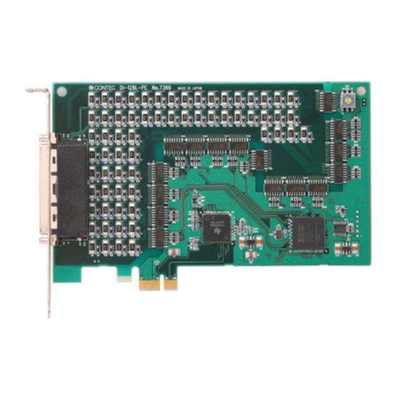
Contec DI-128L-PE User Manual
Digital i/o board with opto-isolation for pci express, digital input board with opto-isolation.
Hide thumbs
1
2
3
Table Of Contents
4
5
6
7
8
9
10
11
12
13
14
15
16
17
18
19
20
21
22
23
24
25
26
27
28
29
30
31
32
33
34
35
36
37
38
39
40
41
42
43
44
45
46
47
48
49
50
51
52
53
54
55
56
57
58
59
60
61
62
63
64
65
66
67
68
69
70
71
72
73
74
75
76
77
page
of
77
Go
/
77
Contents
Table of Contents
Troubleshooting
Bookmarks
Table of Contents
Copyright
Trademarks
Table of Contents
1 Before Using the Product
About the Board
Features
Support Software
Cable & Connector (Option)
Accessories (Option)
Customer Support
Web Site
Limited Three-Years Warranty
How to Obtain Service
Liability
Safety Precautions
Safety Information
Handling Precautions
Environment
Inspection
Storage
Disposal
2 Setup
What Is Setup
Using the Board under Windows Using the Driver Library API-PAC(W32)
Using the Board under Windows Using Software Other than the Driver Library API-PAC(W32)
Using the Board under an os Other than Windows
Step 1 Installing the Software
About the Driver to be Used
Starting the Install Program
Select API-DIO(WDM)
Select API-DIO(98/PC)
Step 2 Setting the Hardware
Parts of the Board and Factory Defaults
Setting the Board ID
Plugging the Board
Step 3 Installing the Hardware
Turning on the PC
When Using API-DIO(WDM)
When Using API-DIO(98/PC)
Step 4 Initializing the Software
When Using API-DIO(WDM)
When Using API-DIO(98/PC)
Updating the Settings
Step 5 Checking Operations with the Diagnosis Program
What Is the Diagnosis Program
Check Method
Using the Diagnosis Program
Setup Troubleshooting
Symptoms and Actions
If Your Problem Cannot be Resolved
3 External Connection
How to Connect the Connectors
Connector Shape
Connector Pin Assignment
Relationships between API-PAC(W32) Logical Ports/Bits and Connector Signal Pins
Connecting Input Signals
Input Circuit
Connecting to the Switch
Connecting Output Signals
Output Circuit
Connecting to the LED
Example of Connection to TTL Level Input
Connecting the Sink Type Output and Sink Output Support Input
4 Function
Data I/O Function
Data Input
Data Output
Monitoring Output Data
Digital Filter Function
Digital Filter Function Principle
Set Digital Filter Time
Interrupt Control Function
Disabling/Enabling Interrupts
Selecting the Edge of Input Signals, at Which to Generate an Interrupt
Clearing the Interrupt Status and Interrupt Signal
5 About Software
CD-ROM Directory Structure
About Software for Windows
Accessing the Help File
Using Sample Programs
Uninstalling the Driver Libraries
About Software for Linux
Driver Software Install Procedure
Accessing the Help File
Using Sample Programs
Uninstalling the Driver
6 About Hardware
For Detailed Technical Information
Hardware Specification
Block Diagram
Advertisement
Quick Links
Download this manual
PC-HELPER
Digital I/O Board with Opto-Isolation
for PCI Express,
DIO-6464L-PE
Digital Input Board with Opto-Isolation
DI-128L-PE
Digital Output Board with Opto-Isolation
DO-128L-PE
User's Guide
CONTEC CO.,LTD.
Table of
Contents
Previous
Page
Next
Page
1
2
3
4
5
Advertisement
Table of Contents
Need help?
Do you have a question about the DI-128L-PE and is the answer not in the manual?
Ask a question
Questions and answers
Related Manuals for Contec DI-128L-PE
I/O Systems Contec DIO-48DX-USB User Manual
Bi-directional digital i/o unit for usb (47 pages)
I/O Systems Contec DI-64T2-PCI User Manual
Digital input/output boards for pci (57 pages)
I/O Systems Contec DIO-1616TB-PE User Manual
Digital i/o board with high-speed opto-isolation for pci express (63 pages)
I/O Systems Contec DIO-3232L-PE User Manual
Digital i/o board for pci express digital input board with opto-isolation digital output board with opto-isolation (67 pages)
I/O Systems Contec DIO-6464L-PE User Manual
Digital i/o board with opto-isolation for pci express, digital input board with opto-isolation. (77 pages)
I/O Systems Contec DIO-1616L-PE User Manual
(69 pages)
I/O Systems Contec DIO-48D2-PCI User Manual
Bi-directional digital i/o board for pci (66 pages)
I/O Systems Contec F&eIT Series User Manual
(76 pages)
I/O Systems Contec DIO-8D(FIT)GY User Manual
Bi-directional digital input/output module (51 pages)
I/O Systems Contec DIO-1616RY-PE User Manual
Digital i/o board with high voltage isolation for pci express (62 pages)
I/O Systems Contec DIO-128SLX-USB Quick Start Manual
Bi-directional digital i/o unit with opto-isolation for usb (8 pages)
I/O Systems Contec N Series Quick Start Manual
Isolated digital i/o unit(16ch di, 16ch do) (7 pages)
I/O Systems Contec DIO-1616H-PE User Manual
Opto-isolated digital i/o for pci express 16 ch type, 32 ch type (63 pages)
I/O Systems Contec DIO-96D2-LPCI User Manual
Bi-directional digital i/o board for pci low profile (65 pages)
I/O Systems Contec DI-32T2-PCI User Manual
Digital input/output board for pci (62 pages)
I/O Systems Contec DIO-1616RYX-USB User Manual
Digital i/o unit with high voltage isolation for usb (47 pages)
This manual is also suitable for:
Do-128l-pe
Dio-6464l-pe
Table of Contents
Print
Rename the bookmark
Delete bookmark?
Delete from my manuals?
Login
Sign In
OR
Sign in with Facebook
Sign in with Google
Upload manual
Upload from disk
Upload from URL


Need help?
Do you have a question about the DI-128L-PE and is the answer not in the manual?
Questions and answers