Advertisement
Manual call point DKM 3.3 – bus capable for STG 1.2
Technical Data
Power supply:
Power consumption:
LED displays:
Alarm:
Short-circuit:
Alarm- + short-circuit:
Alarm- + fault signal:
Rated operating
temperature:
Rated storage
temperature:
Rated humidity:
Gehäuse:
Dimensions (L x W x D):
Weight:
Protection type:
Connections:
Colors:
Product description / Function
The DKM communicates with the STG via the safety-monitored
system ringbus. The detectors forward fault and alarm mes-
sages to the STG and indicated on a display. A technician or
building manager can therefore see all connected detectors at a
glance. Important .
Note: Please also note separate specification sheets for STG 1.2.
17 – 31 V DC
from STG 1.2 via system bus
Switch-off current 100 µ A
Standby current 250 µ A
Alarm current 620 µ A
Short-circuit current 8 mA
Rated continuous current 1 A
red LED on
yellow LED on
yellow LED on
via bus on STG 1.2
-10 – + 50 °C
-30 °C – + 60 °C
95 % RH (at 40 °C)
ABS plastic
135 x 135 x 37 mm
approx. 0.3 kg
IP52 / IP54 (with gasket)
6 x screw terminals 1.5 mm²
blue, yellow, red
•
For Oppermann control unit STG 1.2
•
Power supply and communication via safety
ringbus
•
Housings in different colors
•
LED display on alarm (red) and short circuit
(yellow)
•
Custom labeling on request
•
Installation-friendly housing
•
Straightforward installation
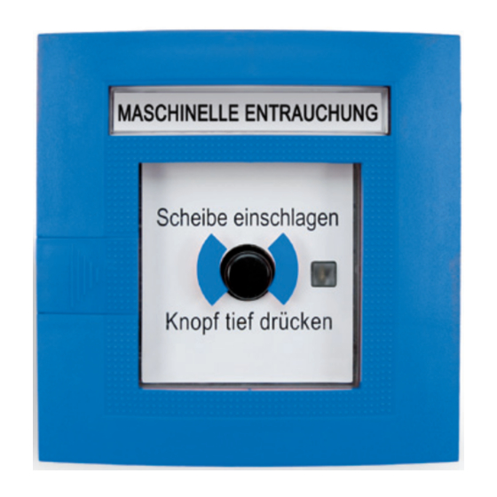
The manual call point consists of the plastic housing and door.
It contains the circuit board with terminals, trigger mechanism,
and push-button. The replaceable standardized thin glass
pane in a lockable door (protected by a standardized lock) is
a safeguard against unintended triggering. In the event of an
alarm, the glass pane is easily broken and the pushbutton can
be pressed without interference. A special retainer keeps the
button in the pressed position. The manually actuated retainer
lever is used to release the push button. The particularly low-
profile configuration of the manual call point eliminates the
need for in-wall installation.
The detector has cable connection terminals on top and on the
bottom. An opening can be punched out on the rear face of
the detector for installation on an in-wall cup. In the event of
an alarm, the glass pane (2) is punched in first, and the push-
button (3) is then pressed deeply. This actuates the micro-
switch to trigger the alarm; display LED (4) lights up. A locking
mechanism retains the engaged push-button. The engaged
push-button is reset by manually actuating the reset lever (5) or
by opening the detector door (1). The alarm is reset and the LED
(4) goes dark. The alarm must also be reset on the STG.
1
2
1
3
2
3
Fire Protection | Data sheet No. 49103 | Version 01-2016 | 1 | 6
5
4
5
4
3
3
1
1
2
2
Advertisement
Table of Contents

Related Manuals for Oppermann Regelgeräte DKM 3.3


Summary of Contents for Oppermann Regelgeräte DKM 3.3
- Page 1 Manual call point DKM 3.3 – bus capable for STG 1.2 • For Oppermann control unit STG 1.2 • Power supply and communication via safety ringbus • Housings in different colors • LED display on alarm (red) and short circuit (yellow) •...
-
Page 2: Installation Instructions
Manual call point DKM 3.3 – bus capable Installation instructions • All work must only be performed by sufficiently qualified trades- Manual detectors must be sufficiently illuminated by daylight men. The respectively applicable local rules and regulations (e.g. or an alternative light source (including emergency lighting, if national building codes, electrical/VDE regulations, etc.) must be... -
Page 3: Installation Dimensions
Manual call point DKM 3.3 – bus capable Installation dimensions 135 mm 13 mm 60 mm Space requirements toward the right to open the detector approx. 35mm ca. 35 mm In-wall installation Surface-mounted installation (remove circuit board first) x 40 mm... -
Page 4: Electrical Connection
Manual call point DKM 3.3 – bus capable Electrical connection All work on electrical installations or equipment must only be performed by a trained electrician or by an instructed person under the direction and supervision of a trained electrician in accordance with electrical engineering principles. - Page 5 Manual call point DKM 3.3 – bus capable Wiring 4 − 7 mm 8 − 10 mm Fire Protection | Data sheet No. 49103 | Version 01-2016 | 5 | 6...
- Page 6 Fault indicator/analog value display (only on DRM) The programming cable is only needed for push button alarm DKM 3.3 Programming is only possible when the detector is disconnected from power. Programming is not possible if the loop is connected to power. Programming is also not possible during an alarm. Reset the alarm first.
Need help?
Do you have a question about the DKM 3.3 and is the answer not in the manual?
Questions and answers