
Related Manuals for Grant Vortex Pro VTX15/21


Summary of Contents for Grant Vortex Pro VTX15/21
- Page 1 Grant Vortex Pro Utility and Utility System Condensing Oil Boiler Range Installation and Servicing Instructions UK | DOC 0120 | Rev 1.4 | October 2018...
- Page 2 This manual is accurate at the date of printing but will be superseded and should be disregarded if specifications and/or appearances are changed in the interests of continued product improvement. However, no responsibility of any kind for any injury, death, loss, damage or delay however caused resulting from the use of this manual can be accepted by Grant Engineering (UK) Limited, the author or others involved in its publication.
-
Page 3: Table Of Contents
COntEntS intRODUCtiOn fLUE SYStEm anD aiR SUppLY How a condensing boiler operates Air supply Boiler description Conventional flue systems Flue options Connecting a conventional flue Boiler components Balanced flue systems Prepare the wall tEChniCaL Data Flue clearances Boiler technical data Sealed system data COmmiSSiOninG Burner settings... -
Page 4: Introduction
Extensions 225 mm, 450 mm, 950 mm fitted. • Adjustable 275 to 450 mm All the models in the current Grant Vortex Pro range of boilers are • Vertical concentric balanced flue kit designed to comply with the maximum NOx emissions* under the •... -
Page 5: Boiler Components
If required, an additional flexible fuel line (600 mm) and 3/8” to 1/4” BSP male adaptor are available to purchase from Grant UK, for two-pipe oil supply systems (Grant product code: RBS104). The temperature of the water leaving the boiler to heat the radiators and hot water cylinder is user adjustable. -
Page 6: Technical Data
tEChniCaL Data BOiLER tEChniCaL Data table 2-1: Boiler technical data Utility Utility System Units 15/21 15/26 26/36 36/46 46/58 58/70 15/26 26/36 36/46 litre 16.5 Water content 126.5 Weight (dry) Maximum heat output (Kerosene) Btu/h 71,700 88,700 122,800 157,000 197,900 238,800 88,700 122,800... -
Page 7: Burner Settings
The data given above is approximate only and is based on the boiler being used with a low level balanced flue. The above settings may have to be adjusted on site for the correct operation of the burner. Gas Oil is NOT suitable for use with Grant Vortex boiler range The flue gas temperatures given above are ± 10%. -
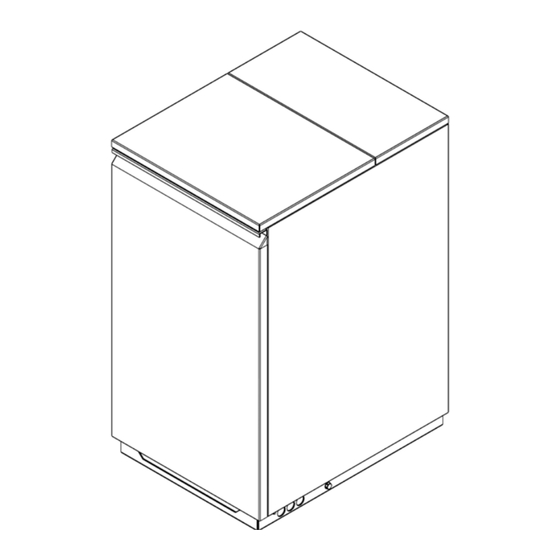
Page 8: Boiler Dimensions
BOiLER DimEnSiOnS PLAN VIEW INTERNAL DRAIN TRAP EXIT (LEFT SIDE PANEL ONLY) REAR VIEW RIGHT SIDE VIEW LEFT SIDE VIEW figure 2-4: Vortex Pro Utility 15/21 dimensions REV DISCRIPTION: 18/04/18 JOB TITLE: DRAWING TITLE: BP 05 VORTEX I N DOOR 15_21 PANEL SET. a sm DWG NO: 22624 REV:... - Page 9 PLAN VIEW INTERNAL DRAIN TRAP EXIT (LEFT SIDE PANEL ONLY) REAR VIEW LEFT SIDE VIEW RIGHT SIDE VIEW figure 2-6: Vortex Pro Utility 26/36, 36/46 and Utility System 26/36, 36/46 dimensions PLAN, ELEVATION, REV DISCRIPTION: 20/12/16 JOB TITLE: DRAWING TITLE: BP 07 VORTEX 26_46 I N DOOR PANEL ASSEMBLY .
-
Page 10: Oil Storage And Supply System
BS 5410-2. • ¼ʺ isolating valve (product code: ISOLATION1/4) Oil storage tanks should comply with the following standards: These are available to purchase from Grant UK. • Plastic tanks OFT T100 Metal braided flexible fuel hoses should be replaced ANNUALLY •... - Page 11 figure 3-1: Single pipe (gravity) system figure 3-2: Two pipe system figure 3-3: De-aeration device system Key to oil supply diagrams Oil tank External wall Burner Isolating valve Oil filter (15μm max. filtration size) Non-return valve Oil strainer Fire valve sensor De-aerator* Fire valve to BS5410 Oil pump...
-
Page 12: Burner Oil Connection
¼ʺ isolating valve (product code: ISOLATION1/4) port and that the plastic plug is discarded. These are available to purchase from Grant UK. The burner fuel pump is supplied factory set for use with a single pipe (gravity) oil supply system. - Page 13 Fit the ¼ʺ isolating valve (supplied with the boiler) to the end of the rigid oil supply pipe using a fitting to suit the pipe size These are available to purchase from Grant UK. and type (not supplied). Connect the oil supply to the burner oil pump as follows:...
-
Page 14: Installation
Installation of a Grant Vortex boiler must be in accordance with temperatures of less than 40°C when the system is up to the following recommendations: temperature. -
Page 15: Pipework Materials
4.5 pipEWORK matERiaLS inStaLLinG thE BOiLER The Grant Vortex boiler is compatible with both copper and plastic Having decided upon the position of the boiler and type of pipe. Where plastic pipe is used it must be of the oxygen barrier flue, prepare the wall as described in Section 9. -
Page 16: Pipe Connections
pipE COnnECtiOnS WatER COnnECtiOnS The Flow and Return pipework can be routed to either side of Heating flow the boiler, dependant on the type and direction of the flue system Heating return used. Thermostat phials For condensate disposal pipework refer to Section 6. A drain cock is fitted at the bottom on the front of the boiler to allow the heating system to be drained. -
Page 17: Condensate Disposal
COnDEnSatE DiSpOSaL GEnERaL REQUiREmEntS pipEWORK When in condensing mode the Grant Vortex boilers produce Condensate disposal pipework must be plastic (plastic waste or condensate from the water vapour in the flue gases. overflow pipe is suitable). This condensate is moderately acidic with a pH value of around ! nOtE ! 3.27 (similar to orange juice). -
Page 18: Condensate Soakaway
Grant product COnDEnSatE DiSpOSaL guarantee. -
Page 19: External Condensate Trap Fitting
Rear panel Disconnect condensate discharge hose from heat exchanger and condensate trap and remove it from the boiler. Replace with condensate trap hose (Grant product code: VBS107). Pass the straight connector end of the hose through the new hole in the left hand casing panel. Push the straight... -
Page 20: Sealed Systems
SEaLED SYStEm ! nOtE ! REQUiREmEntS All Grant Vortex Pro models are suitable for use with sealed Ensure that the expansion vessel used is of sufficient size systems complying with the requirements of BS EN 12828, BS EN for the system volume. -
Page 21: Filling The Sealed System
system. This can be done manually (where allowed by the local operating the safety valve until the system design pressure is water undertaking) using an approved filling loop arrangement obtained. incorporating a double check valve assembly. 10. Close the fill point and double check valves either side of the The filling loop must be isolated and disconnected after filling the filling loop and disconnect the loop. -
Page 22: Electrical
! nOtE ! If a Grant plug-in programmer is used, a permanent 230 V mains supply (fused at 5 Amp) must be taken to the boiler. A three core cable is required to connect the boiler terminal block to the live Remove the BROWn link between the boiler terminal 1 and supply. -
Page 23: Control System Wiring Diagrams
(if fitted) Wiring Centre Frost Thermostat Pump Supply to burner Grant 2-Channel Wall Mounted Programmer Boiler Terminal Block (Ref. ESKIT) Remove link 1 to 4 when plug-in programmer is fitted figure 8-1: Utility models with 3-port valve control system Grey... - Page 24 Pipe Thermostat (if fitted) Wiring Centre Frost Thermostat Pump Burner Grant 2-Channel Boiler Wall Mounted Programmer Terminal Blocks (Ref. ESKIT) Remove link 1 to 4 when plug-in programmer is fitted figure 8-3: Utility System models with 3-port valve control system...
-
Page 25: Boiler Control Panel Wiring Diagrams
The factory fitted link between terminals 1 & 4 MUST be removed Boiler when the plug-in programmer is Terminal Block fitted to the control panel. OPTIONAL: Grant Electronic 7-day plug-in programmer (Ref. EPKIT) Boiler Control Limit On/Off Switch Thermostat Thermostat... -
Page 26: Flue System And Air Supply
The top and bottom of the annular space must be sealed. Grant recommends the use of the Grant ‘Orange’ flue system, specifically designed for the Vortex range of condensing boilers. - Page 27 ‘Green’ system components as listed in Figure 9-14. Grant Vortex oil fired condensing boilers. Grant recommends the use of the Grant ‘Green’ and ‘Orange’ flue The pack includes a terminal/top plate/flexi flue adaptor, stainless system components for this application. Refer to Section 1.3 for steel smooth bore flexible flue liner, a rigid to flexi adaptor and a details.
- Page 28 Boiler flue connector (from CFA 15/70 kit) Boiler Boiler figure 9-7: Hybrid flue system using Grant Orange and Green figure 9-6: Grant Orange flue system in a typical brick chimney systems components page 28 Section 9: flue System and air Supply...
-
Page 29: Connecting A Conventional Flue
All are suitable for use with Class C2 Kerosene. instructions supplied with the flue kit. If the Grant ‘Green’ system (100 mm rigid twin-wall flue) is to be ! nOtE ! fitted to the boiler then the Grant CF adaptor kit (product code: CFA15/70) must be used –... - Page 30 The maximum flue length - from the top of the boiler flue outlet The following items are additionally available: to the outer face of the wall - is 10 metres for all Grant Vortex • Extensions to extend the flue by 225 mm, 450 mm or 950 boilers.
- Page 31 Top plate to two 45° elbows. The Grant Red system flexible stainless steel liner is directional. The arrows marked on the liner MUST be pointing vertically upwards, following the direction of the flue gases. Failure to...
- Page 32 Vertical terminal kit GTV90 (15 - 26 kW) GTV200 (26 - 70 kW) 45 elbow kit GE45/90 (15 - 26 kW) GE45/200 (26 - 70 kW) High level terminal kit GTH90 (15 - 26 kW) GTH200 (26 - 70 kW) Typical Extended wall bracket ue system...
-
Page 33: Prepare The Wall
pREpaRE thE WaLL 9.5.2 hiGh LEVEL anD VERtiCaL BaLanCED fLUE 9.5.1 LOW LEVEL BaLanCED fLUE If the boiler is to be used with the high level balanced flue (White If the boiler is to be used with a low level balanced flue (Yellow system) make the hole in the wall as shown in Figure 9-17. -
Page 34: Flue Clearances
fLUE CLEaRanCES page 34 Section 9: flue System and air Supply... - Page 35 Further guidance can be obtained from BS 5410-1:2014, OFTEC Book 4 (Installation) and Approved Document J. Grant UK flue products are fully compliant with the CE (Communauté Européenne/European Community) standards having undergone rigorous product testing. Section 9: flue System and air Supply...
-
Page 36: Commissioning
10 COmmiSSiOninG To ensure safe and efficient operation, it is essential that a Grant Vortex Pro boiler is commissioned as detailed in the following procedure. To access the controls, remove the front panel from the boiler (pull forward at the top and then lift off). -
Page 37: Before Switching On
10.1 BEfORE SWitChinG On 10.2 BURnER SEttinGS: RDB2.2 Bx BURnERS Ensure the boiler is isolated from the electrical supply and the boiler On/Off switch is set to OFF. fOR 15/21, 15/26, 26/36 anD 36/46 mODELS Check that the high limit thermostat bulb and boiler With the burner removed from the boiler: thermostat bulb are correctly located in their respective On the 15/26 models - first remove the recirculation tube... - Page 38 ! nOtE ! ! nOtE ! the distance between the end of the burner head and the front face of the diffuser (D) mUSt be correctly set for the Do not overtighten the fixing screw as this may damage burner to operate correctly. the electrode insulator.
-
Page 39: Burner Settings
10.3 BURnER SEttinGS: + 0.5 RDB3.2 BURnERS fOR 46/58 anD 58/70 mODELS With the burner removed from the boiler: figure 10-7: Ignition electrode settings model Utility 46/58 and 58/70 • To adjust the diffuser position: Loosen the diffuser clamp screw. Slide diffuser along the nozzle holder to give the correct gap (A). -
Page 40: Air Adjuster Disc
10.4 aiR aDjUStER DiSC: 10.5 SWitChinG On Switch on the electricity supply to the boiler. 15/21 anD 15/26 mODELS OnLY Set the boiler On/Off switch to ON. A neon on the switch ! nOtE ! lights when it is in the ON position. The boiler will now light automatically. -
Page 41: Running The Boiler
10.6 RUnninG thE BOiLER 10.8 COmpLEtiOn Relight the boiler and allow it to run for at least 20 minutes. With the system hot, check again for leaks, rectifying where necessary. Drain the system while it is hot to complete the Check the smoke number, if it is 0-1 then it is satisfactory. -
Page 42: Servicing
11 SERViCinG 11.2 DiSmantLinG pRiOR tO To ensure safe and efficient operation it is essential that a Grant Vortex Pro boiler is serviced at regular intervals of no longer than SERViCinG 12 months. The procedure for dismantling the boiler is as follows: Servicing and replacement of parts must only be carried out by a suitably qualified engineer. - Page 43 figure 11-1: Baffles (15/21 models) figure 11-4: Baffles (46/58 models) figure 11-2: Baffles (15/26 models) figure 11-5: Baffles (58/70 models) Position in vertical plane IMPORTANT: The ends of the turbulators must be vertical figure 11-3: Baffles (26/36 and 36/46 models) figure 11-6: Turbulators Section 11: Servicing page 43...
-
Page 44: Cleaning The Burner
11.4 CLEaninG thE BURnER: ! nOtE ! RDB2.2 Bx BURnERS OnLY fOR 15/21, 15/26, 26/36 anD 36/46 mODELS the distance between the end of the burner head and the With the burner removed from the boiler: front face of the diffuser (D) mUSt be correctly set for the Burner head, nozzle and diffuser/electrode assembly: burner to operate correctly. -
Page 45: Cleaning The Burner: All Models
11.5 CLEaninG thE BURnER: 11.6 CLEaninG thE BURnER: RDB3.2 BURnERS OnLY aLL mODELS fOR 46/58 anD 58/70 mODELS photocell The photocell is a push-fit in the front of burner body. Refer to With the burner removed from the boiler: Sections 11.9.1 and 11.9.2. Remove the burner head. -
Page 46: Burner Components
11.9 BURnER COmpOnEntS 11.9.1 UtiLitY 15/21, 15/26, 26/36, 36/46 anD UtiLitY SYStEm 15/26, 26/36 anD 36/46 (RiELLO RDB 2.2 Bx) item Description item Description Oil pump Air inlet Air damper adjustment screw Motor Reset button with lockout lamp Motor ignition capacitor Photocell Fuel suction line Control box... - Page 47 11.9.2 UtiLitY 46/58 anD 58/70 (RiELLO RDB 3.2) item Description item Description Reset button with lockout lamp Pump pressure adjustment screw Photocell Extension for gauge connection Air inlet Oil pump Combustion head Flange with insulating gasket Control box Air damper adjustment screw Section 11: Servicing page 47...
-
Page 48: Fault Finding
12 faULt finDinG 12.1 BOiLER faULt finDinG Always isolate the electricity supply to the boiler before working on the boiler. figure 12-1: Boiler fault finding fault Remedies Boiler will not start: Ensure that an adequate supply of fuel is available and that the fuel supply valve is open. -
Page 49: Burner Fault Finding - Riello Rdb
12.2 BURnER faULt finDinG - RiELLO BURnERS Section 12: fault finding page 49... -
Page 50: Spare Parts
13 SpaRE paRtS 13.1 BOiLER paRtS LiSt table 13-1: Boiler parts list Description Grant UK product code Cleaning door nut and washer set EFBS14 Double pole switch EFBS19 Baffle set (complete) - 15/21 VBS93 Baffle set (complete) - 15/26 VBS01... -
Page 51: Riello Rdb 2.2 Burners
13.3 RiELLO RDB 2.2 Bx BURnERS (15/21, 15/26, 26/36 anD 36/46 mODELS) This section gives exploded views of the Riello burners in the Grant Vortex boilers, and parts lists associated with them. Section 13: Spare parts page 51... - Page 52 page 52 Section 13: Spare parts...
- Page 53 Section 13: Spare parts page 53...
-
Page 54: Riello Rdb 3.2 Burners
13.4 RiELLO RDB 3.2 BURnERS (46/58 anD 58/70 mODELS) This section gives exploded views of the Riello burners in the Grant Vortex boilers, and parts lists associated with them. page 54 Section 13: Spare parts... - Page 55 Section 13: Spare parts page 55...
-
Page 56: Declaration Of Conformity
Indoor Grant Vortex Pro Utility System 15-26, 26-36 and 36-46 Indoor Note: All Grant system variants are supplied with glandless high efficiency integrated circulators in accordance with the following Directives: 2006/95/EEC Conforms with the safety objectives of the Low Voltage Directive and its amending directives. -
Page 57: Health And Safety Information
15 hEaLth anD SafEtY infORmatiOn 15.3 KEROSEnE anD GaS OiL fUELS Under the Consumer Protection Act 1987 and Section 6 of the Health & Safety at Work Act 1974, we are required to provide (minERaL OiLS) information on substances hazardous to health (COSHH Regulations 1988). -
Page 58: End Of Life Information
16 EnD Of LifE infORmatiOn GEnERaL Grant oil boilers incorporate components manufactured from a variety of different materials. The majority of these materials can be recycled whilst the smaller remainder cannot. Materials that cannot be recycled must be disposed of according to local regulations using appropriate waste collection and/or disposal services. -
Page 59: Product Fiche
17 pRODUCt fiChE Product fiche concerning the COMMISSION DELEGATED REGULATIONS (EU) No 811/2013 of 18 February 2013 (EU) No 813/2013 of 2 August 2013 Vortex pro Utility Symbols Unit Condensing boiler Low temperature boiler B1 boiler Combination heater Rated heat output Prated Useful heat output At rated heat output and high temperature... -
Page 60: Guarantee
18 GUaRantEE You are now the proud owner of a Grant Vortex condensing boiler free of charge repairs from Grant Engineering (UK) Limited which has been designed to During the two year guarantee period no charge for parts or give years of reliable, trouble free operation. - Page 61 • The balance of the guarantee is transferable providing the installation is serviced prior to the dwelling’s new owners taking up residence. Grant Engineering (UK) Limited must be informed of the new owner’s details. • The Company will endeavour to provide prompt service in the unlikely event of a problem occurring, but cannot be held responsible for any consequences of delay however caused.
- Page 62 nOtES page 62 notes...
- Page 63 notes page 63...
- Page 64 GRant EnGinEERinG (UK) LimitED Hopton House, Hopton Industrial Estate, Devizes, Wiltshire, SN10 2EU Tel: +44 (0)1380 736920 Fax: +44 (0)1380 736991 Email: info@grantuk.com www.grantuk.com...
Need help?
Do you have a question about the Vortex Pro VTX15/21 and is the answer not in the manual?
Questions and answers