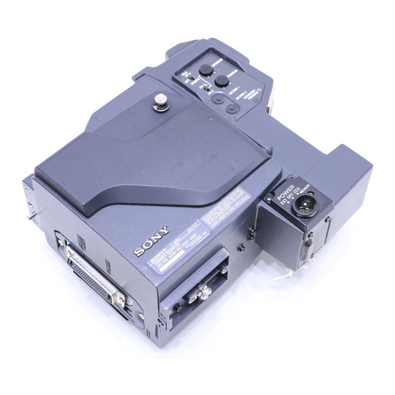
Summary of Contents for Sony CA-TX7/TX7P
- Page 1 3-859-844-13(1) Camera Adaptor Operating Instructions Before operating the unit, please read this manual thoroughly and retain it for future reference. CA-TX7/TX7P 1997 by Sony Corporation...
- Page 2 WARNING To prevent fire or shock hazard, do not expose the unit to rain or moisture. To avoid electrical shock, do not open the cabinet. Refer servicing to qualified personnel only. This symbol is intended to alert the user to the presence of uninsulated “dangerous voltage”...
-
Page 3: Table Of Contents
Table of Contents Overview ... 4 Location and Function of Parts ... 5 Front and Left Side ... 5 Switches and Knobs on the Rear and Right Side ... 7 Connectors on the Rear and Right Side ... 9 Mounting on Video Camera ... 11 Notes on Use ... -
Page 4: Overview
Consult your Sony dealer for details. The CA-TX7/TX7P Camera Adaptor, which is docked with a DXC-D30/ D30P or DXC-637 series Color Video Camera, allows connecting the camera to the CCU-TX7/TX7P Camera Control Unit via a triaxial cable. -
Page 5: Location And Function Of Parts
Note Use a DXC-D30/D30P with ROM of ver. 1.1 or later. For version check and ROM change, consult your Sony dealer. 2 TALK switch Selects whether or not to transfer intercom audio from the camera to the camera control unit. - Page 6 After resolving the problem, press this button to reset the breaker. If the breaker gets activated even after correcting the connection, contact your Sony dealer. 8 POWER switch Turns this unit’s power supply on and off. To power the unit, set the switch to EXT or CCU according to the type of power source being used.
-
Page 7: Switches And Knobs On The Rear And Right Side
Switches and Knobs on the Rear and Right Side 1 Cursor knobs 2 TALLY switch 3 Back tally indicator 4 CALL button 5 AUDIO SELECT (CH1/CH2) switches 6 MIC IN +48V (CH1/CH2) switch 1 Cursor knobs (for DXC-D30/D30P) When the CURSOR switch 8 is set to A or B, this adjusts the position and size of the box cursor that is displayed in the viewfinder of the DXC-D30/D30P. - Page 8 Location and Function of Parts 6 MIC IN +48V (CH1/CH2) switch Selects whether or not to supply power to a microphone connected via the MIC IN CH1 and CH2 connectors. ON: Supplys +48-V power to microphone. OFF: Do not supply power to microphone. Leave this switch in the ON position when using a microphone of phantom powering 7 UHF portable tuner taps...
-
Page 9: Connectors On The Rear And Right Side
Contact your Sony dealer for further information on this internal adjustment. 2 PROMPTER OUT (teleprompter video signal output) connector (BNC type) Outputs teleprompter video signals control unit. - Page 10 Use a CMA-8A/8ACE AC Adaptor for AC power sources. Contact your Sony dealer for more information on refitting the CCU connector. 6 DATA connector (10-pin)
-
Page 11: Mounting On Video Camera
Mounting on Video Camera Using the DXC-D30/D30P Loosen the two screws (M3) and remove the cover from the PRO 50-pin connector. Note Never loosen the other screws. Press the right side of the PRO 50-pin connector until the PRO 76-pin DIGITAL connector appears. -
Page 12: Mounting On The Camera
Mounting on Video Camera Attach the cover upside down. Make sure that the match mark lines up with “PRO 76P DIGITAL” indication. Using the DXC-637 series camera Mounting on the camera If necessary, replace the PRO 50-pin connector with the PRO 76-pin DIGITAL connector. - Page 13 Fit the projection on the bottom of this unit into the slot on the camera. Slide the unit along the groove on the camera, and press firmly until fixed. Tighten the two screws (M4 12) in the figure. Camera Slot Groove 12 screws Projection...
-
Page 14: Removing From The Camera
Mounting on Video Camera Tighten the two screws (M4 6) to fix the shoulder pad. Note Slide the shoulder pad to its central position before tightening the screws. Otherwise the screws may not be properly fixed. Removing from the camera Notes on Use Use and storage locations Avoid using or storing the unit in the following places:... -
Page 15: Specifications
D30P+DXF-51/51CE 1) The power consumption indicated on the name plate of the unit is total consumption of the CA-TX7/TX7P outputting 12 W from the DC OUT connector, DXC- D30/D30P, and DXF-51/51CE. When power is supplied via the DC IN connector... -
Page 16: Specifications
PRO 76-pin DIGITAL or PRO 50- Accessories supplied Operating instructions (1) Accessories not supplied Triaxial cable (Belden) CCQX-3 DC Power Cord CMA-8A/8ACE AC Adaptor WRR-810A UHF Portable Tuner Design and specifications are subject to change without notice. Sony Corporation Printed in Japan...


Need help?
Do you have a question about the CA-TX7/TX7P and is the answer not in the manual?
Questions and answers