
Related Manuals for Ormesa Juditta B30

Summary of Contents for Ormesa Juditta B30
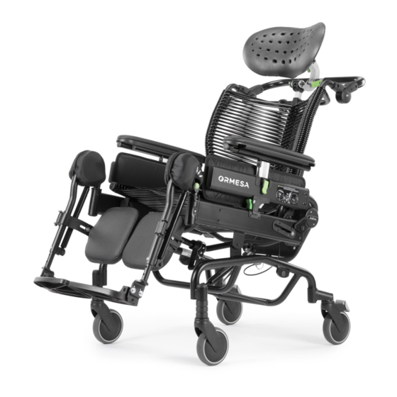
- Page 1 tilt-in-space wheelchair model model model USE AND MAINTENANCE HANDBOOK...
- Page 3 If, after reading it, you still have questions, contact your retailer, who will be happy to help you, or call ORMESA directly at +39 0742 22927, send a fax to +39 0742 22637 or send an e-mail to: info@ormesa.com...
-
Page 4: Table Of Contents
TABLE OF CONTENTS WARNINGS........................... 4 GUARANTEE ..........................6 HOW TO STORE AND TRANSPORT THE MEDICAL DEVICE ............ 6 SOME EXAMPLES OF WHAT NOT TO DO WITH JUDITTA ............7 HOW TO TILT THE WHEELCHAIR AND CLIMB UP PAVEMENTS..........8 HOW TO FACE UP TO SLOPES IN GETTING ON AND OFF (B60 version) ......... 11 HOW TO USE JUDITTA FOR TRANSPORT ON A MOVING VEHICLE (private cars, bus, etc..) 12 HOW TO FIX THE 891 TIEDOWN (4 RINGS) ON THE FRAME ............ - Page 5 TURNING THE CALF RESTS ......................41 DEPTH ADJUSTMENT of the CALFRESTS................... 42 FLESSO-EXTENSION of the CALFRESTS ..................42 ADJUSTING THE HEIGHT OF THE ARMRESTS ................43 OPENING THE SIDE SUPPORTS ....................44 ADJUSTING THE HEADREST....................... 45 ADJUSTING THE DEPTH OF THE SEAT..................47 HEIGHT ADJUSTMENT OF THE BACKREST ................
-
Page 6: Warnings
- The manual reflects the technical state of the product at the time it was sold. ORMESA reserves the right to make any changes to the product or manual suggested by experience, technical considerations or regulatory developments... - Page 7 REFER ONLY TO ORMESA, otherwise warranty and marking will be voided In case of about the of the product...
-
Page 8: Guarantee
GUARANTEE ORMESA guarantees the product for 2 years ; in case of problems, contact the retailer where you purchased it. Always ask for original spare parts, otherwise the guarantee will decline ORMESA will not be liable for damage in the following cases: - use by an unsuitable person;... -
Page 9: Some Examples Of What Not To Do With Juditta
STROLLER TO TIP OVER (SEE FIG. PAGE 10) - DO NOT USE JUDITTA WHEELCHAIR IN THE SHOWER: its steel structure is not suitable for that purpose. Contact ORMESA S.r.l. or your retailer for a specific painted aluminium aid made for that purpose DO NOT USE THE PRODUCT IF PARTS ARE MISSING OR DAMAGED. -
Page 10: How To Tilt The Wheelchair And Climb Up Pavements
HOW TO TILT THE WHEELCHAIR AND CLIMB UP PAVEMENTS VIEW FROM ABOVE Turned off anti-tip device PEDAL TO CLIMB STEPS FOR JUDITTA B30 VIEW FROM ABOVE PEDAL TO CLIMB STEPS Turned off FOR JUDITTA B60 anti-tip device 8/86... - Page 11 CLIMB FACING FORWARD WARNING! TAKE THE BACKREST AND NOT THE PUSH HANDLE PEDAL TO CLIMB STEPS PEDAL TO CLIMB STEPS FOR JUDITTA B30 FOR JUDITTA B60 DESCEND FACING BACKWARD Turned off anti-tip device Turned off anti-tip device UDITTA B30 JUDITTA B60...
- Page 12 10/86...
-
Page 13: How To Face Up To Slopes In Getting On And Off (B60 Version)
HOW TO FACE UP TO SLOPES IN GETTING ON AND OFF (B60 version) Help is needed to get on and off ramps and slopes The user can still get on a slight climb by himself, as JUDITTA B60 has an anti-tip device. -
Page 14: How To Use Juditta For Transport On A Moving Vehicle (Private Cars, Bus, Etc
WARNINGS! ORMESA RECOMMENDS THE USE OF A COMPLETE ISO 10542-2 COMPLIANT “WTORS” SYSTEM, which consists of restraint systems for both the wheelchair and its occupant - Whenever the user is transferred on a seat of the vehicle, the unoccupied wheelchair... -
Page 15: How To Fix The 891 Tiedown (4 Rings) On The Frame
HOW TO FIX THE 891 TIEDOWN (4 RINGS) ON THE FRAME only for B30 and B60 version WARNINGS: - Suitable for ISO 10542-approved four-point straps provided in the vehicle. To anchor the wheelchair to the transport vehicle see the instructions on page 14 - The User has to wear both a lap belt and a diagonal shoulder belt ISO 7176-19- or ISO 10542-approved (i.e. - Page 16 2) HOW THE WHEELCHAIR IS TO BE SECURED IN A VEHICLE (private cars, bus, etc..) HOOK THE APPROVED 4-POINT BELTS OF THE VEHCLE TO THE 891 4 TIEDOWN HOOKS (4 RINGS) AS SHOWN IN THE FIGURE AND IN THE DIRECTION OF TRAVEL OF THE VEHICLE DIRECTION OF TRAVEL OF THE VEHICLE...
- Page 17 3) CORRECT POSITIONING OF THE OCCUPANT BELT RESTRAINTS ON THE USER ATTENTION! The pelvic belt restraint should be worn low across the front of the pelvis, so that the angle of the pelvic belt restraint is within the preferred zone of 30° to 75° to the horizontal (see fig.
-
Page 18: Labels And Plates
LABELS AND PLATES Name of the model Series number Article number ® s.r.l. Via A. Da Sangallo, 1 06034 Foligno (PG) ITALY Tel. +39 074222927 Fax +39 074222637 M O D E L . P A R T N ° MAX. -
Page 19: Conformity Declaration
CONFORMITY DECLARATION ORMESA S.r.l. GUARANTEES AND DECLARES, under its own exclusive responsibility, that the following Medical Device, technical aid for rehabilitation: which this declaration refers to, conforms with the general requirements provided in the medical devices Directive 93/42/EEC and subsequent amendments and additions,... -
Page 20: About Juditta Wheelchair. Intended Use
ABOUT JUDITTA WHEELCHAIR. Intended use JUDITTA wheelchair was designed based on more than twenty-five years of experience with the elderly and disabled and is intended for hospital and home use. It may be used outside if the warnings and instructions of this manual are observed, especially the paragraphs “Warnings”... -
Page 21: Technical Features And Models
TECHNICAL FEATURES and MODELS JUDITTA is available in 3 models: JUDITTA B30 (tilt-in-space): with 20 cm front solid swiveling wheels and 30 • cm rear wheels; drum brakes are operated by a single control pedal. JUDITTA B12 (tilt-in-space): with four 12cm solid swiveling wheels, the rear •... - Page 22 Dimensions in cm size 36 size 40 size 45 size 50 (TILT-IN-SPACE) Seat bottom width Seat bottom depth Backrest width Total width Seat bottom inclination (tilt) Backrest inclination Aid weight Max capacity Hyphen-separated numbers indicate the minimum and maximum range of adjustment 20/86...
- Page 23 Dimensions in cm size 36 size 40 size 45 size 50 (TILT-IN-SPACE) Seat bottom width Seat bottom depth Backrest width Total width Seat bottom inclination (tilt) Backrest inclination Aid weight Max capacity Hyphen-separated numbers indicate the minimum and maximum range of adjustment 21/86...
- Page 24 Dimensions in cm 180° ROTATION 360° ROTATION size 36 size 40 size 45 size 50 (TILT-IN-SPACE) Seat bottom width Seat bottom depth Backrest width Total width Seat bottom inclination (tilt) Backrest inclination Aid weight Max capacity Hyphen-separated numbers indicate the minimum and maximum range of adjustment 22/86...
-
Page 25: Initial Preparation
INITIAL PREPARATION PACKING INFORMATION VOLUME WEIGHT Size 36 Size 36 Size 45 Size 50 VOLUME WEIGHT Size 36 Size 36 Size 45 Size 50 VOLUME WEIGHT Size 36 Size 36 Size 45 Size 50 23/86... - Page 26 HOW TO REMOVE JUDITTA WHEELCHAIR FROM THE BOX WARNING! CUT WITHOUT PRESSING TOO HARD PRESS GENTLY WITH THE KNIFE SO AS NOT TO DAMAGE THE CONTENTS OF THE BOX REMOVE THE ACCESSORIES TILT THE BOX AND TAKE CARE NOT TO SCRAPE THE CONTENTS DURING REMOVAL JUDITTA AFTER BEING TAKEN OUT 24/86...
-
Page 27: Assembly
ASSEMBLY BOTH SIDES 25/86... - Page 28 26/86...
- Page 29 BOTH SIDES 27/86...
- Page 30 CLAMPING LEVER INSERT THE HEADREST AND LOCK IT WITH THE CLAMPING LEVER 28/86...
- Page 31 CLICK INDICATES THAT IT IS WELL LOCKED MAKE SURE THAT THE LEGRESTS ARE WELL INSERTED AND DO NOT ROTATE 29/86...
-
Page 32: How To Fix Self-Propelling Wheels (B60 Version)
HOW TO FIX SELF-PROPELLING WHEELS (B60 version) WARNNG! to remove the self propelling wheels, do the inverse procedure 30/86... -
Page 33: Activation Of The Anti-Tip Device (B60 Version)
ACTIVATION of the ANTI-TIP DEVICE (B60 version) Anti-tip device on To deactivate the anti-tip device reverse the procedure. See the following Figure. Anti-tip device off 31/86... -
Page 34: Using Juditta Wheelchair
USING JUDITTA WHEELCHAIR BRAKING THE WHEELCHAIR ( B30 MODEL ) VIEW FROM ABOVE BRAKE PEDAL WARNNG! BEFORE THE USER GETS IN OR OUT OF THE WHEELCHAIR, AND BEFORE LOCK ADJUSTING ANY OF ITS PARTS, YOU MUST BRAKE THE AID UNLOCK 32/86... -
Page 35: Braking The Wheelchair ( B12 Models With Four 12Cm Wheels)
BRAKING THE WHEELCHAIR ( B12 MODELS ) LOCK WARNING! BEFORE THE USER GETS IN OR OUT OF THE WHEELCHAIR, AND BEFORE ADJUSTING ANY OF ITS PARTS, YOU MUST BRAKE THE AID UNLOCK BRAKING THE WHEELCHAIR ( B60 MODEL ) LOCK UNLOCK 33/86... -
Page 36: Adjusting The Tilt Of The Backrest
ADJUSTING THE TILT OF THE BACKREST REAR VIEW Backrest adjustment lever INSERT THE PIN IN THE HOLE OF THE LEVER TO LOCK THE BACKREST ADJUSTMENT 34/86... -
Page 37: Adjusting The Inclination Of The Seat Bottom (Tilt- In- Space)
ADJUSTING THE INCLINATION OF THE SEAT BOTTOM (TILT- IN- SPACE) REAR VIEW Tilting lever INSERT THE PIN IN THE HOLE OF THE LEVER TO LOCK THE TILT/INCLINATION 35/86... -
Page 38: Closing The Footrests
CLOSING THE FOOTRESTS ADJUSTING THE FOOTRESTS IN HEIGHT 1. UNSCREW THE NUTS AND REMOVE THE SCREWS USING THE SUPPLIED WRENCH 2. POSITION THE FOOTRESTS AT THE DESIRED HEIGHT INSERT THE SCREWS AND TIGHTEN THE NUTS wrench 36/86... -
Page 39: Flex. Extension Adjustment Of The Footrests
FLEX. EXTENSION ADJUSTMENT OF THE FOOTRESTS LOOSEN THE TWO SCREWS USING THE WRENCH ADJUST THE FOOTRESTS IN FLEX. EXTENSION TIGHTEN THE SCREWS Screw Wrench 37/86... -
Page 40: Turning The Legrests
TURNING THE LEGRESTS PRESS THE LOCK BUTTON RISE THE LEGRESTS SLIGHTLY AND TURN OUTSIDE WARNING! CLOSE THE LEGREST ROTATING IT UP TO THE INITIAL POSITION (inwards).A CLICK WILL CONFIRM THE RIGHT LOCK Lock button 38/86... -
Page 41: Removing The Legrests
REMOVING THE LEGRESTS PRESS THE LOCK BUTTON REMOVE THE LEGREST Lock button 39/86... - Page 42 ADJUSTING THE LEGREST INCLINATION 1. PUSH THE KNOB DOWN 2. AT THE SAME TIME ADJUST THE INCLINATION OF THE LEGREST Knob 40/86...
-
Page 43: Turning The Calf Rests
TURNING THE CALF RESTS 41/86... -
Page 44: Depth Adjustment Of The Calfrests
DEPTH ADJUSTMENT of the CALFRESTS wrench depth adjustment nut FLESSO-EXTENSION of the CALFRESTS 42/86... -
Page 45: Adjusting The Height Of The Armrests
ADJUSTING THE HEIGHT OF THE ARMRESTS Locking lever FRONT VIEW Unlock Lock Locking lever 43/86... -
Page 46: Opening The Side Supports
OPENING THE SIDE SUPPORTS 1. PUSH THE BUTTON 2. ROTATE THE SIDE UP Button Button OPEN SIDES WARNING! ! CLOSE THE SIDE JUST ROTATING UP TO THE HORIZONTAL POSITION. A CLICK WILL CONFIRM THE RIGHT LOCK FOR SAFETY REASONS, THE SIDE HAS FRICTION (BRAKING) OPENING; CHECK ITS CORRECT FUNCTIONING PERIODICALLY (AS SPECIFIED ON PAGE 83) 44/86... -
Page 47: Adjusting The Headrest
ADJUSTING THE HEADREST WARNINGS! - FIRST ADJUST THE HEADREST IN SIDE TRANSLATION, THEN GO ON WITH THE OTHER ADJUSTMENTS - USE BOTH HANDS TO ADJUST THE HEADREST SIDE VIEW unlock Locking lever lock REAR VIEW RIGHT TRANSLATION LEFT TRANSLATION 45/86... - Page 48 1. LOOSEN THE THREE LOCKING LEVERS LOOSEN THE CLAMPING LEVER ADJUST THE HEIGHT OF THE 2. ADJUST THE INCLINATION AND DEPTH HEADREST OF THE HEADREST TIGHTEN THE CLAMPING LEVER TIGHTEN THE LOCKING LEVERS CLAMPING LEVER LOCKING LEVERS LOCKED LEVER UNLOCKED LEVER TOP VIEW 46/86...
-
Page 49: Adjusting The Depth Of The Seat
ADJUSTING THE DEPTH OF THE SEAT You can adjust the seat depth by adjusting: the two screws on the sides the central bush under the seat For a right positioning see the chart on page LOOSEN THE TWO SCREWS ON THE RIGHT AND LEFT SIDES MOVE THE BACKREST IN THE DESIRED POSITION TIGHTEN THE TWO SCREWS Wrench... - Page 50 OPEN THE SPRING OF THE PIN OF THE CENTRAL BUSH UNDER THE SEAT PULL THE PIN 3- 4 MOVE THE CENTRAL BUSH (THEN THE BACKREST) AS SPECIFIED ON THE CHART ON PAGE LOCK THE SPRING Central bush Pin spring 48/86...
- Page 51 WARNINGS! FOLLOW THE INSTRUCTIONS IN THE CHART A DIFFERENT POSITIONING FROM THE INDICATED ONE AFFECTS THE POSTURE AND THE STABILITY OF THE WHEELCHAIR Seat depth Position Position Position Position 49/86...
-
Page 52: Height Adjustment Of The Backrest
HEIGHT ADJUSTMENT OF THE BACKREST LOOSEN THE FOUR SCREWS BEHIND THE BACKREST ADJUST THE BACKREST HEIGHT TIGHTEN THE FOUR SCREWS REAR VIEW Screw Wrench 50/86... -
Page 53: Tilt Adjustment Of The Push Handle
TILT ADJUSTMENT OF THE PUSH HANDLE BUTTON 51/86... -
Page 54: Removing The Upholstery For The Washing
REMOVING THE UPHOLSTERY FOR THE WASHING STUDS FOR THE WASHING, FOLLOW THE INSTRUCTIONS GIVEN ON PAGE 83 CLEAN THE PADS OF THE LEGRESTS WITH A SPONGE. DO NOT MACHINE WASH 52/86... - Page 55 REAR VIEW OF THE BACK BELTS WITH STUDS ALWAYS ATTACH THE BELTS ON THE FIRST THREE CORDS (AS IN THE FIGURE ABOVE) WE RECOMMEND TO FIX THE UPHOLSTERY WITH OPEN ARMRESTS 53/86...
-
Page 56: Assembling The Accessories
ASSEMBLING THE ACCESSORIES 824-R RECLINABLE TABLE RIGHT AND LEFT 1. Pull the stopper out destornillador stopper left locking part of the tray 3. rotate 45°outwards 2. Put the stopper in the locking part of the tray 4. insert the cap and the try lock in the tube of the armrest using a rubber hammer 54/86... - Page 57 5. hit the tray lock with the rubber hammer slightly so that is inserts into the tube slot 6. pull the stopper out using a screwdriver stopper 7. insert the spring into the slot of the tray lock Spring 55/86...
- Page 58 8. turn the locking part of the tray outwards 9. tighten the screw wrench ASSEMBLED 56/86...
- Page 59 INSERTION AND FIXING WARNING A. insert the tray so that the top is horizontal B. lock the indicated lever C. Before changing the inclination of the seat bottom (tilt-in-space) MAKE SURE THAT THERE ARE NO HOT OBJECTS or LIQUID CONTAINERS on the tray, that could cause DAMAGE or BURNS if they spill FIRST INSERT THE LONGER TABLE ROD TO FACILITATE INSERTION...
- Page 60 ADJUSTMENT ADJUSTING THE DEPTH OF THE TABLE 1) press the safety lever 2) open the locking lever pressing the safety lever down (repeat the operation on the other side) 3) adjust the tray in depth 4) lock the right and left locking levers safety lever locking lever 58/86...
- Page 61 ADJUSTING THE TILT OF THE TABLE VIEW FROM BELOW unlocked lever locked lever 59/86...
- Page 62 SETTING OF CONTROL LOCKING LEVERS should you have noticed an INEFFICIENCY, even partially, on the LOCKING of the GREEN LEVERS of the TRAY adjustments, please contact your ORTHOPAEDIC WORKSHOP to ADJUST IT WITH LITTLE INCREASES, as shown here below, up to the ACHIEVEMENT OF THE PROPER FASTENING depth adjustment lever wrench tilt adjustment lever...
-
Page 63: Abduction Block 834
ABDUCTION BLOCK WARNING! TIGHTEN THE KNOB WELL 61/86... -
Page 64: Footrest Lock 914
FOOTREST LOCK - ASSEMBLING the footrest lock WRENCH M5x30 SCREWS BUSHES LOCKING MECHANISM FOR SINGLE FOOTREST WRENCH NUTS M5x35 SCREWS 62/86... - Page 65 UNLOCKING the footrest lock LOCKING LEVER - OPERATING the footrest lock LOCKING LEVER 63/86...
-
Page 66: Calf Rest 916
CALF REST REMOVE THE KNEE PADS 64/86... - Page 67 FIX THE CALF REST (916) Adjust the depth by loosening the velcro 65/86...
-
Page 68: Removable Footplate Cover 892
REMOVABLE FOOTPLATE COVER WARNING! IN ORDER TO FIX THE PADDED COVER OF THE FOOTREST IT IS NECESSARY TO FIX THE 914 FOOTREST LOCK FOOTREST LOCK 914 VIEW FROM BELOW OF THE FOOTREST 66/86... -
Page 69: Removable Table Cover 896
REMOVABLE TABLE COVER VIEW FROM BELOW OF THE TABLE 67/86... -
Page 70: Headrest Removable Cover 936
HEADREST REMOVABLE COVER REAR VIEW OF THE HEADREST ELASTIC TIEDOWN HOOKS (4 RINGS) Only for B30 and B60 JUDITTA WHEELCHAIR conforms to the ISO 7176-19 and ANSI RESNA WC/19 standard, which defines the safety requirements for transport, facing in the direction of travel on moving vehicles (private cars, buses, etc.) FOR THE ASSEMBLY OF THE 891 ACCESSORY AND ANCHORING THE... -
Page 71: Pole 933 (B30 And B12 Version)
IV POLE (B30 and B12 version) 69/86... - Page 72 70/86...
-
Page 73: Set Of Hand Brakes 905 (B30 Version)
(B30 version) SET OF HAND BRAKES ASSEMBLE THE BRAKE LEVER AND THE DOUBLER cable control doubler Strap 71/86... - Page 74 Strap Strap Strap 72/86...
- Page 75 REMOVE THE REAR WHEELS wheel tap M12 screw Spacer REMOVE THE BRAKE SYSTEM screw wrench brake system 73/86...
- Page 76 ASSEMBLE THE RIGHT AND LEFT BRAKES, THE CABLE-LOCK PLATES AND THE WHEELS wheel tap M12 screw wrench screw M6 right plate for hand brake right hub Spacer right brake cable lock cable cable control sheath transparent external sheath 74/86...
-
Page 77: Set Of Hand Brakes 905 (B60 Version)
SET OF HAND BRAKES (B60 version) cable control doubler Strap 75/86... - Page 78 Strap Strap Strap 76/86...
- Page 79 77/86...
- Page 80 cable lock cable cable control internal view 78/86...
- Page 81 Hand brake lever sheath doupler B60 wheel with drum brake 79/86...
-
Page 82: 932 Anti-Tip Up Device (B30 Version)
ANTI-TIP UP DEVICE (B30 version) DISASSEMBLY OF THE WHEELS wheel cap M12 screw wrench spacer DISASSEMBLY OF THE HUBS AND BRAKE SET M6 screw wrench M12 screw wrench 80/86... - Page 83 ASSEMBLY OF THE LEFT/RIGHT ANTI-TIP UP DEVICE wrench M6 screw M12 screw Wrench ASSEMBLY OF THE BRAKE SET wheel cap M12 screw ASSEMBLY OF THE WHEELS wrench spacer 81/86...
- Page 84 ACTIVATION of the ANTI-TIP DEVICE BEWARE! brake the wheelchair before activating the device Anti-tip device on To deactivate the anti-tip device reverse the procedure. See the following Figure. Anti-tip device off 82/86...
-
Page 85: Chest Strap 828
BEWARE! In case of HYPERKINETIC patients, the Anti-tip up device, art. 932, is recommended when JUDITTA is used tilted and reclined. Outside this case, it is recommended to deactivate the device, which would make the handling of the wheelchair more difficult. anti-tip device CHEST STRAP REAR VIEW... -
Page 86: Maintenance, Cleaning And Disinfection
MAINTENANCE, CLEANING AND DISINFECTION REGULAR (OR PREVENTIVE) MAINTENANCE ) MONTHLY PERFORM ORDINARY MAINTENANCE OF THE AID AND OF ITS ACCESSORIES. REGULAR MAINTENANCE IS REQUIRED TO KEEP THE PRODUCT WORKING PROPERLY AND SAFELY AND IS ESSENTIAL FOR KEEPING THE MARK. THE MANUFACTURER IS NOT LIABLE FOR THE PERFORMANCE OF THE PRODUCT UNLESS REGULAR MAINTENANCE IS PERFORMED (ATTACHMENT I, DIRECTIVE 2007/47/CE). -
Page 87: Customer Service And Spare Parts
LUBRICATION The product does not need any special lubrication except if the wheels are not turning freely. In these cases, use a commercial grease spray, paying attention to the warnings on the container. AFTER LUBRICATION, DRY THE TREATED PARTS WELL TO REMOVE THE RESIDUAL LUBRICANT. -
Page 88: Conditions For Durability, Reuse And Reassignment To Anew User
Prior to recycling or reassignment an already used Ormesa product, it is required that: 1. a doctor or therapist verifies that the aid is appropriate and adequate to meet the dimensional, functional and postural needs of the new user, and if all its components are suitable / appropriate for him. - Page 92 COMPANY WITH QUALITY MANAGEMENT SYSTEM CERTIFIED BY SINCE 1980 Authorized Dealer The technical Data and information given in this handbook are not binding. ORMESA reserves the right to carry out any necessary change without prior notice or replacements...
Need help?
Do you have a question about the Juditta B30 and is the answer not in the manual?
Questions and answers