Table of Contents
Advertisement
Quick Links
Advertisement
Table of Contents

Related Manuals for Trademaster BM-21


Summary of Contents for Trademaster BM-21
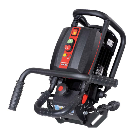
- Page 1 OPERATOR’S MANUAL BM-21 BEVELLING MACHINE...
- Page 2 You are also entitled to have the goods repaired or replaced if the goods fail to be of acceptable quality and the failure does not amount to a major failure. Read Operator’s Manual before you start to work with the machine Operator’s Manual – BM-21 Bevelling Machine...
-
Page 3: Table Of Contents
STARTUP AND OPERATION.............8 3.1. Preparing to operation..............8 3.2. Adjusting bevel width and angle...........9 3.3. Bevelling metal plates..............10 3.4.Bevelling pipes................10 3.5.Bevelling larger pipes (only for optional equipment)....13 3.6.Replacing cutting inserts.............14 3.7.Replacing milling head..............15 WIRING DIAGRAM................16 Operator’s Manual – BM-21 Bevelling Machine... -
Page 4: General Information
1. GENERAL INFORMATION 1.1. Application The BM-21 Bevelling Machine is designed for milling edges of plates and pipes made of carbon steel. The machine enables the bevelling of sheet steel edges and pipe edges with diameters from 150 mm (6’’) to 300 mm (12’’) in 0–60° angular range with maximum bevel width of 21 mm (13/16’’). -
Page 5: Equipment Included
Milling tool is equipped with 10 removable multi-edge cutting inserts made of carbide. Figure 1. Bevel dimensions 1.3. Equipment included BM-21 Bevelling Machine is supplied in metal box with complete standard equipment. The included equipment consists of: • bevelling machine with a set of cutting inserts –... -
Page 6: Safety Precautions
Never remove hot and sharp metal chips with bare hands. Securely fasten cutting inserts in milling head using fastening screws. WARNING! Do not hold rotating parts of the machine or metal chips formed during milling! Operator’s Manual – BM-21 Bevelling Machine... - Page 7 If machine falls on a hard surface, from a height, is wet or has other damage that could affect technical state of machine, stop operation and immediately send machine to service centre for inspection. WARNING! Do not hold rotating parts. Safety rules must be closely observed. Operator’s Manual – BM-21 Bevelling Machine...
-
Page 8: Startup And Operation
Bevelling is performed according to counter-rotation. The proper feed direction is shown in Figure 2; direction of milling head rotation is indicated on the motor disc under milling head cover. Figure 2. Control panel design and proper machine feed direction Operator’s Manual – BM-21 Bevelling Machine... -
Page 9: Adjusting Bevel Width And Angle
You can obtain maximum bevel width (b 21 mm, 13/16’’) for the angle of 45°. Experimentally determine the required bevel width for individual angles, by gradually increasing milling head penetration into the working piece. Figure 3. Adjusting bevel width and angle Operator’s Manual – BM-21 Bevelling Machine... -
Page 10: Bevelling Metal Plates
(Figure 4b, Item 5) touching the pipe. Then, move rollers (Figure 4a, 4b, Item 3) symmetrically to touch the pipe and secure with bolts (Figure 4b, Item 4) in this position. Adjust required bevel width and angle (see “Adjusting bevel width and angle”) and start to work with bevelling machine. Operator’s Manual – BM-21 Bevelling Machine... - Page 11 Figure 4a. Machine prepared for work on metal plates Operator’s Manual – BM-21 Bevelling Machine...
- Page 12 Figure 4b. Machine prepared for work on pipes Operator’s Manual – BM-21 Bevelling Machine...
-
Page 13: Bevelling Larger Pipes (Only For Optional Equipment)
You can optionally order the guide for bevelling larger pipes with diameters 260–600 mm ( 10–24’’, Figure 6). To prepare the machine for work on larger pipes, proceed as described in previ- ous section. Figure 6. Machine prepared for work on larges pipes ( 260–600 mm, 10–24’’) Operator’s Manual – BM-21 Bevelling Machine... -
Page 14: Replacing Cutting Inserts
3.6. Replacing cutting inserts BM-21 Bevelling Machine is equipped with uniform milling head (Figure 8, Item 1), containing two insert rings, each holding five cutting inserts, for a total of 10 inserts. The inserts can be replaced or rotated. Perform this work only with power cord unplugged from power socket. To replace or rotate the insert, unscrew lever (Figure 7, Item 1), remove pitch (Figure 7, Item 2) and remove milling head cover (Figure 7, Item 3). -
Page 15: Replacing Milling Head
Then, use size 8 Allen key to unscrew bolt (Figure 10, Item 2) and remove milling head. Size 32 flat key is not included in standard equipment. Figure 10. Replacing milling head Operator’s Manual – BM-21 Bevelling Machine... -
Page 16: Wiring Diagram
4. WIRING DIAGRAM Operator’s Manual – BM-21 Bevelling Machine... - Page 17 Parts list BM-21S v.1.04 This document is protected by copyrights. Copying, using, or distributing without permission of PROMOTECH is prohibited.
- Page 18 Parts list BM-21S v.1.04 ITEM PART NUMBER DESCRIPTION PWD-0461-17-00-00-0 POWER CORD - 230V PWD-0461-17-00-00-1 POWER CORD - 115V PWD-0461-17-00-00-2 POWER CORD - 230V (AU) SLN-0505-01-00-00-2 MOTOR ASSY - 230V SLN-0505-01-00-00-3 MOTOR ASSY - 115V ZBI-0461-02-00-00-0 DRIVING RING PKT-0461-04-00-00-0 KNOB OSL-0461-05-00-00-0 MILLING HEAD COVER PRW-0505-02-01-00-0 VERTICAL GUIDE...
- Page 19 Parts list BM-21S v.1.04 ITEM PART NUMBER DESCRIPTION SRB-000141 HEX. SOCKET BOLT M8x14 SRB-000156 HEX. SOCKET BOLT M8x35 SRB-000046 HEX. SOCKET BOLT M10x25 SRB-000309 HEX SOCKET BOLT M10x120 SRB-000148 HEX. SOCKET BOLT M8x20 WZK-0461-09-07-00-0 STOP BUTTON WIRE SET WZK-0461-09-08-00-0 CONTROLLER PLATE GROUNDING WIRE WZK-0461-09-09-00-0 MOTOR GROUNDING WIRE WKR-000446...
- Page 20 Parts list BM-21S v.1.04 SLN-0505-01-00-00-2 MOTOR ASSY - 230V SLN-0505-01-00-00-3 MOTOR ASSY - 115V ITEM PART NUMBER DESCRIPTION TRC-0461-01-02-00-2 BEARING DISK N TRC-000024 BEARING DISK P KDL-000003 STATOR BODY - 230V KDL-000004 STATOR BODY - 110V WRN-000051 ROTOR PDK-000195 CLEARANCE REMOVAL SPRING WASHER OSL-000193 FAN COVER WNT-000008...
Need help?
Do you have a question about the BM-21 and is the answer not in the manual?
Questions and answers