Table of Contents
Advertisement
Quick Links
BM-20 PLUS
BEVELLING MACHINE
OPERATOR'S MANUAL
PART# WA-B20+
BEFORE USE, ENSURE EVERYONE USING THIS MACHINE READS AND UNDERSTANDS
ALL SAFETY AND OPERATING INSTRUCTIONS IN THIS MANUAL .
Serial #............................................
Date of Purchase............................
Ver: 1.0
01/05/2015
Advertisement
Table of Contents

Related Manuals for Trademaster BM-20 Plus


Summary of Contents for Trademaster BM-20 Plus
- Page 1 BM-20 PLUS BEVELLING MACHINE OPERATOR’S MANUAL PART# WA-B20+ BEFORE USE, ENSURE EVERYONE USING THIS MACHINE READS AND UNDERSTANDS ALL SAFETY AND OPERATING INSTRUCTIONS IN THIS MANUAL . Serial #..........Date of Purchase......Ver: 1.0 01/05/2015...
-
Page 2: Table Of Contents
3.2. Operating 3.3. Replacing the cutting inserts 3.4. Replacing the milling cutters 4. ACCESSORIES 4.1. 0° guide set for facing plates 4.2. Guides for bevelling pipes 5. WIRING DIAGRAM 6. SPARE AND WEARING PARTS 7. PARTS BREAKDOWN BM-20 PLUS Operator’s Manual... -
Page 3: General Information
Machine harmful for health. Take Vibration level periodic breaks during operation. Weight 20.5 kg (45 lbs) 15° 30° 45° 60° 21 mm 20.5 mm 21 mm 20.5 mm Fig. 1. Bevel dimensions; maximum bevel width depending on the angle BM-20 PLUS Operator’s Manual... - Page 4 446 mm (17.6’’) BM-20 PLUS Operator’s Manual...
-
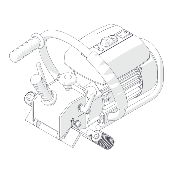
Page 5: Design
Guide set Bevel angle pitch Fig. 2. View of the machine and control panel 1.4. Equipment included The BM-20 plus is supplied in a metal box with complete standard equipment. The included equipment consists of: Bevelling machine 1 unit Cutting insert... -
Page 6: Safety Precautions
Never remove metal chips with bare hands. Clean the machine with a cotton cloth without using any agents. 20. Cover steel parts with a thin anti-corrosion coating to protect the machine from rust when not in use for any extended period. BM-20 PLUS Operator’s Manual... - Page 7 23. If the machine falls from any height, is wet, or has other damage that could affect the technical state of the machine, stop the operation and immediately send the machine to the service center for inspection and repair. BM-20 PLUS Operator’s Manual...
-
Page 8: Startup And Operation
Then, to set the required bevel angle (Fig. 4), use the 6 mm hex wrench to loosen two side screws, rotate the guide set to set the angle on the pitch, and tighten the screws in this new position. Fig. 4. Setting the bevel angle (45° is set on the drawing) BM-20 PLUS Operator’s Manual... -
Page 9: Operating
12 mm (1/2’’) should be accomplished in at least two or three passes as this will require less effort and the process will take less total time than for bevelling in a single pass. BM-20 PLUS Operator’s Manual... - Page 10 Once the work is finished, stop the motor using the STOP button and toggle the power switch to the position ‘O’. Clean the machine with a cotton cloth without using any agents. BM-20 PLUS Operator’s Manual...
-
Page 11: Replacing The Cutting Inserts
Next, place the 90° rotated insert again or replace with a new one if all four edges of the insert are worn. Set screw Fig. 7. Replacing the cutting inserts BM-20 PLUS Operator’s Manual... -
Page 12: Replacing The Milling Cutters
Fig. 9. Assemble in reverse order. The 26 mm flat wrench is not included in standard equipment. Milling cutter no. 2 Milling cutter no. 1 Fig. 9. Replacing the milling cutters BM-20 PLUS Operator’s Manual... -
Page 13: Accessories
Then, mount the 0° guide set in such a way to obtain the indication of 45° on the right pitch, and secure with the same screws. Fig. 10. Dismounting the standard guide set and mounting the 0° guide set BM-20 PLUS Operator’s Manual... -
Page 14: Guides For Bevelling Pipes
Fig. 10. Then, use the 4 mm hex wrench to unscrew four screws from the dismounted guide set and assemble the guide set for pipes as indicated (Fig. 11). Fig. 11. Assembling the guide set for pipes BM-20 PLUS Operator’s Manual... - Page 15 Then, move the rollers symmetrically to adjoin them to the pipe (Fig. 13) and tighten in this position. Set the required bevel angle and width as described before. Fig. 13. Machine prepared for work on pipes with diameters of 150–300 mm and 300–600 mm BM-20 PLUS Operator’s Manual...
-
Page 16: Wiring Diagram
5. WIRING DIAGRAM BM-20 PLUS Operator’s Manual... -
Page 17: Spare And Wearing Parts
Milling cutter no. 2 (5 cutting inserts required) KRP-0539-03-00-00-0 Cutting insert (sold 10 per box) PLY-000282 Mounting screw for inserts SRB-000311 T15P torx screwdriver for mounting screws WKT-000005 Grease for screws (5 g, 0.17 oz) SMR-000005 BM-20 PLUS Operator’s Manual... -
Page 18: Parts Breakdown
7. PARTS BREAKDOWN BM-20 PLUS Operator’s Manual... - Page 19 BM-20 PLUS Operator’s Manual...
- Page 20 BM-20 PLUS Operator’s Manual...
- Page 21 BM-20 PLUS Operator’s Manual...
Need help?
Do you have a question about the BM-20 Plus and is the answer not in the manual?
Questions and answers