Table of Contents
Advertisement
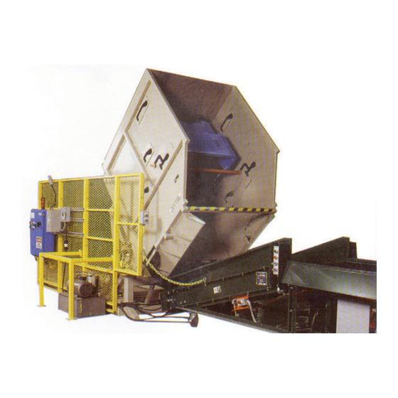
Operating and Maintenance Manual
APCU Series
All Purpose Container Unloader
Model #: APCU
Serial # _________________________________________
Placed in Service _________________________________
Southworth Products Corp
P.O. Box 1380 • Portland, ME 04104-1380
Telephone: 207-878-0700 Fax: 207-797-4734
December 2018
Advertisement
Table of Contents
Troubleshooting

Subscribe to Our Youtube Channel
Related Manuals for Southworth APCU Series


Summary of Contents for Southworth APCU Series
- Page 1 Operating and Maintenance Manual APCU Series All Purpose Container Unloader Model #: APCU Serial # _________________________________________ Placed in Service _________________________________ Southworth Products Corp P.O. Box 1380 • Portland, ME 04104-1380 Telephone: 207-878-0700 Fax: 207-797-4734 December 2018...
- Page 2 This label (part # 10095524) is required by California law. For more information visit www.65Warnings.ca.gov. This label (part # 10095524) is required by California law. For more information visit www.P65Warnings.ca.gov. APCU Owner’s Manual...
-
Page 3: Table Of Contents
CONTENTS INTRODUCTION ....................4 RESPONSIBILITY OF OWNERS AND USERS ........... 5 SAFETY ALERT SYMBOLS AND SIGNAL WORDS ..........6 SAFETY ......................7 Safety devices ..................8 INSTALLATION INSTRUCTIONS ..............20 Preparation ..................20 Positioning the lift .................. 20 Hydraulic connections ................. 20 Testing .................... -
Page 4: Introduction
Southworth shall not be liable for any loss, injury, or damage to persons or property, nor for any direct, indirect, or consequential damage of any kind resulting from the APCU unit. -
Page 5: Responsibility Of Owners And Users
It is the responsibility of the user/purchaser to advise the manufacturer where deflection may be critical to the application. Repairs All repairs shall be made by qualified personnel in conformance with Southworth’s instructions. Operators Only trained personnel and authorized personnel shall be permitted to operate the lift. -
Page 6: Safety Alert Symbols And Signal Words
SAFETY ALERT SYMBOLS AND SIGNAL WORDS The safety of all persons operating, maintaining, repairing, or in the vicinity of this equipment is of paramount con- cern. This is a powerful machine with moving parts, and is capable of causing personal injury if proper precautions are not taken. -
Page 7: Safety
Safety Southworth is concerned about the safety of everyone who operates, maintains, repairs, or works near the APCU unit. The unit is a powerful machine with moving parts, and is capable of causing personal injury if proper precautions are not taken. -
Page 8: Safety Devices
Safety Devices This unit has two kinds of safety devices. Guard fences Each photo-eye system includes a light source on one protect each side of the unit. These are designed to side of the unit, and a reflector on the other side. If keep everyone away from the moving parts of the unit any of the light beams is broken, the unit will not start, while it is operating. -
Page 9: Fig. 2A Operating Sequence - Loading Position
Fig. 2A Operating Sequence - Loading Position Fig. 2B Operating Sequence - Tilt 90 degree Position APCU Owner’s Manual... -
Page 10: Fig. 2C Operating Sequence - Dump Position
(See Part C.) you have questions about any of the instructions in this This manual contains information about the safe and manual, please contact Southworth Products Corp. proper installation, use, and maintenance of an APCU Fig. 2C Operating Sequence - Dump Position... - Page 11 APCU Owner’s Manual...
- Page 12 APCU Owner’s Manual...
- Page 13 APCU Owner’s Manual...
- Page 14 APCU Owner’s Manual...
- Page 15 APCU Owner’s Manual...
- Page 16 APCU Owner’s Manual...
- Page 17 APCU Owner’s Manual...
- Page 18 "NOTICE" label p/n-2998591T APCU Owner’s Manual...
- Page 19 Fig. 3H APCU SUPPORT STAND USE PROCEDURE DO NOT USE SUPPORT STANDS FOR HYDRAULIC, ELECTRICAL, MECHANICAL SERVICE OR MAINTENANCE. WHEN ENTERING THE MACHINE'S LOAD AREA FOR OTHER PURPOSES BOTH SUPPORT STANDS MUST BE USED. NOTICE: FAILURE TO FOLLOW THESE SPECIFIC USE PROCEDURES MAY SERIOUSLY DAMAGE THIS EQUIPMENT USING THE CONTROL PUSHBUTTON, RAISE THE TILT FRAME TO THE HIGHEST POSITION.
-
Page 20: Installation Instructions
Installation Instructions Positioning the Lift 1. Remove the shipping material and unskid the unit. Preparation On the front of this manual, write down the model num- 1. Before you start to use the unit, check for local ber, serial number, and date the unit is placed in service. codes and ordinances which may apply. -
Page 21: Testing
Electrical Connections Testing 1. Clear the area around the unit. Remove any ma- DANGER! terials which might get in the way of the load enclosure This unit requires three-phase 460V AC. as it raises or lowers. Be sure that the safety guards This voltage can kill you. -
Page 22: Operator Controls
Fig. 4 Control Panel Operator Controls he control panel on the unit includes several standard controls. See Fig. 4. “Main Disconnect” Switch - This switch controls all electrical power to the unit. “Tilt Up” Button - When the operator presses this button, the unit tilts the load enclosure 90°. - Page 23 As you load the load enclosure, you will break one or 6. Operate the unit. Press the “Tilt Up” button. The load enclosure will tilt 90°. (The machine will complete this more of the 3 photo-eye beams at the front of the unit. part of the cycle by itself - it is not necessary to hold the button.) See Fig.
-
Page 24: Fig. 5A Using The Retainer Bar
Note: Different containers utilize different retaining bar positions. Please keep this in mind as you load each container and make sure that the retaining bar is in the proper position to prevent injury or damage to equipment. The retaining bar should be placed in a position which is as close as possible to the rear of the container unloader. -
Page 25: Fig. 5B Proper Retaining
Fig. 5B Proper Retaining - Using the retainer bar The Post Office supply’s markings for containers and where the retaining bar should be used. These locations should be adhered to for retaining containers and skids. Examples of properly retained containers and skids: When you have BMC or OTR that are over load you will have to level them out before putting it into the unload- ers. - Page 26 APCU with controls 4. Operator turns the “MANUAL/AUTO” selector switch to the “AUTO” position. Operational Description 5. To operate the machine the amber-lighted “GUARD RESET” pushbutton must be pressed. Indicator Proximity Switches If the photoeyes are clear the “GUARD RESET” pushbutton light will turn off.
-
Page 27: Optional Apcu Support Stands
resses with of the “DOWN” pushbuttons. The the problem has been corrected, the machine can operator must hold the pushbutton for three sec- be reset by turning the “MANUAL/AUTO” switch to onds. During this time, the motion alarm will flash the “MANUAL”... -
Page 28: Maintenance
The cylinders and other parts can be removed accordance with accepted practice. For safety’s sake, safely from either the tilt or dump mechanisms when the if in doubt, please contact your dealer or Southworth load enclosure is completely lowered. Normally, you Products Corporation Customer Service Department should never need to work under the load enclosure. -
Page 29: Routine Maintenance-Monthly
They should be able to troubleshoot live electrical circuits safely and in accordance with accepted practice. For safety’s sake, if in doubt, please contact Southworth Products Corporation at (207) 878-0700. Before servicing the unit, read and understand this entire section and the section entitled “Operating In-... -
Page 30: Troubleshooting Table
Symptom Possible Cause Remedy Neither lift mechanism is working: The power for the unit may be switched Turn on the “Main Disconnect” switch. CAUTION! If the tilt function does off. not begin right away, don’t continue The belt conveyor may not be operating. The belt conveyor must be operating for the APCU to to operate the “up”... - Page 31 Symptom Possible Cause Remedy The tilt mechanism raises slowly. The counter-balance valve in this circuit Release the pressure from the system and clean the may be plugged. valve. The tilt mechanism does not lower. The “down” side of the control valve for The “down”...
-
Page 32: Table 1 Hydraulic Oil Specifications
Table 1 – Hydraulic Oil Specifications If the lift will be used at normal ambient temperatures, Southworth Products supplies the unit with Conoco AW 32 oil. This may be replaced by any other good quality oil with 150 SSU at 100° F and rust and oxidation inhibitors and anti-wear properties. -
Page 33: Adjustment & Replacement Procedures
WARNING! Adjustment and f any part of the base plate contacts the Replacement Procedures floor, except for the front lip, you must shim the base of the machine. Aligning the Photo-Eyes: 1. The photo-eyes are part of a system which protects 2. -
Page 34: Setting End Of Travel For "Dump Down" Function
WARNING! hydraulic system by lowering both lifting mecha- f the motor continues to run after the dump nisms completely. Be sure to turn off the power to motion should stop, the machine may be dam- the machine. aged. Move the target so that the motor stops 5. -
Page 35: Repacking A Cylinder
6. At the top end of the rod remove the “keeper” from the upper cylinder clevis and drive out the upper clevis pin. Repeat the same procedure to remove the lower cylinder clevis pin. 7. Push the rod back into the cylinder to drive the hydraulic fluid out through the hose and into the container. -
Page 36: Replacing A Cylinder
Replacing a Cylinder CAUTION! During reassembly, it is very important to Before beginning this procedure, please read and un- keep all of the parts free of dirt, dust, metal derstand this entire section. chips, water, and other contamination. Most of the problems with hydraulic systems are 1. - Page 37 Figure 7 Hydraulic Schematic APCU Owner’s Manual...
- Page 38 Figure 8 Wiring Diagram APCU Owner’s Manual...
- Page 39 Figure 8 Wiring Diagram - Operation Notes Operation Notes: • o operate the machine the green “E-STOP RESET” light must be on. The “E-STOP RESET” light will only turn on when the system emergency stop circuit is closed and the E-STOP RESET pushbutton is operated. Also, the three (3) photo-eyes on the entry side of the machine must not be obstruct- ed and the “GUARD RESET”...
- Page 40 Figure 9 DC Power Supply Kit APCU Owner’s Manual...
- Page 41 If you need to view a larger drawing please call our customer service department at 800-743-1000 and ask for drawing #3064514T Figure 10 APCU Program Ladder Logic APCU Owner’s Manual...
- Page 42 HYDRAULIC POWER UNIT SPECIFICATIONS MOTOR: Baldor: 5HP, 1750 RPM 208/230 - 460V / 3 / 60, 184TC wired for 460. PUMP: Parker gear pump: 0.61 CUIN / Rev with pump adapter and flex coupling for 1750 PSI operation. RESERVOIR: 15 gallon with suction strainer, return filter and drip pan. VALVE MANIFOLD: Parker 2-station parallel manifold with system relief valve, dual counter balance valves and pump unloading valve.
- Page 43 Figure 10B. Hydraulic Power Unit APCU Owner’s Manual...
- Page 44 Figure 10C. Hydraulic Power Unit APCU Owner’s Manual...
-
Page 45: Ordering Replacement Parts
Ordering Replacement Parts Southworth has carefully chosen the components in your lift to be the best avail- able for the purpose. Replacement parts should be identical to the original equipment. Southworth will not be responsible for equipment failures resulting from the use of incorrect replacement parts or from unauthorized modifications of the ma- chine. -
Page 46: Warranty
Labor is not included. This is buyer’s sole remedy. Except as stated herein, Southworth Products Corp. will not be liable for any loss, injury, or dam- age to persons or property, nor for direct, indirect, or consequential damage of any kind resulting from failure or defective operation of said material or equipment.
Need help?
Do you have a question about the APCU Series and is the answer not in the manual?
Questions and answers