Buderus Logano GE515 Installation And Maintenance Instructions Manual
Oil- and gas-fired boilers
Hide thumbs
Also See for Logano GE515:
- Technical manual (80 pages) ,
- Operating instructions manual (16 pages)

Related Manuals for Buderus Logano GE515


Summary of Contents for Buderus Logano GE515
- Page 1 Installation and maintenance Oil- and gas-fired boilers instructions Logano GE515 For heating engineers Please read carefully prior to installation and maintenance.
- Page 2 Updating your documentation Please let us know if you would like to make suggestions to improve our documentation or if you have noticed any errors. Logano GE515 - We reserve the right to make any changes due to technical modifications.
-
Page 3: Table Of Contents
........51 12.2 Making the system operational Logano GE515 - We reserve the right to make any changes due to technical modifications. - Page 4 ........... . 66 Logano GE515 - We reserve the right to make any changes due to technical modifications.
-
Page 5: General
Fuel oil EL Natural gas operating conditions) The Logano GE515 boilers can be operated with the indicated fuels. Select a burner which operates with Comments one of the fuels listed as suitable for the Logano GE515 boiler. The rated output details listed in the "Specification" table are nominal ratings. -
Page 6: Safety
DANGER TO LIFE from risk of electric shock. WARNING! USER NOTE User tip for the optimum utilisation and setting of the device(s) plus useful information. Logano GE515 - We reserve the right to make any changes due to technical modifications. -
Page 7: Please Observe These Notes
CAUTION! Flush existing systems before connecting the boiler. Prevent boiler damage by installing de- sludging equipment into the system return. Logano GE515 - We reserve the right to make any changes due to technical modifications. -
Page 8: Product Description
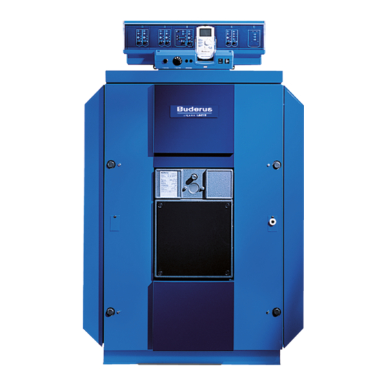
The control device is designed to monitor and control all electrical components of the Logano GE515 oil- and gas-fired special boiler. Fig. 2 Logano GE515 oil- and gas-fired special boiler Boiler shell (casing) Logano GE515 - We reserve the right to make any changes due to technical modifications. -
Page 9: Operating Conditions For Buderus G And Ge Cast Iron Boilers
This shunt pump circuit can be controlled either with a Buderus 4000 control or with a Buderus 4212 fitted with a ZM427 module. -
Page 10: Specification
Depth of burner door Net weight 1270 1430 1590 1753 1900 2060 Boiler water content Gas capacity Weight incl. packaging approx. 6–8 % higher. Logano GE515 - We reserve the right to make any changes due to technical modifications. - Page 11 High limit safety cut-out (safety limit thermostat). Max. possible flow temperature = safety limit (STB) –18 K. Example: Safety limit (STB)= 100 C; max. possible flow temperature = 100 – 18 = 82 °C. In accordance with national standards and guidelines. Logano GE515 - We reserve the right to make any changes due to technical modifications.
-
Page 12: Standard Delivery
Anchor rods Bundle Assembly components Carton (longitudinal rails and feed pipe) Casing pack A, B, C 1–3 Cartons (depending on boiler size) Thermal insulation PU sack Logano GE515 - We reserve the right to make any changes due to technical modifications. -
Page 13: Boiler Handling
Note the following if the boiler is to be stored in its assembled condition: Protect boiler connections by closing or sealing them off. USER NOTE Dispose of packaging in an environmentally responsible manner. Logano GE515 - We reserve the right to make any changes due to technical modifications. -
Page 14: Boiler Positioning
– Wire brush – 3-in-1 oil – Solvent (petrol or solution) – Spirit level, ruler, chalk, straight edge – Blanking flange with vent facility (for pressure test) Logano GE515 - We reserve the right to make any changes due to technical modifications. - Page 15 7–12 3 080 Fig. 5 Boiler compression tool size 2.3 (dimensions in mm) Mating flange Additional flange Compression unit Pull rod Extension Wedge (size 2.3) Logano GE515 - We reserve the right to make any changes due to technical modifications.
-
Page 16: Recommended Wall Clearances
As an alternative we would recommend the use of shorter (length approx. 1 m) cleaning devices or wet cleaning. Logano GE515 - We reserve the right to make any changes due to technical modifications. -
Page 17: Positioning The Boiler On A Sub-Structure Or On Foundations
1 360 1 190 1 530 1 360 1 700 1 530 1 870 1 700 2 040 1 870 2 210 2 040 Logano GE515 - We reserve the right to make any changes due to technical modifications. -
Page 18: Boiler Block Assembly
Rear section prevent them slipping. Return connection Flow connection Centre section Anchor rod Arrow – assembly direction Front section 10 Burner door with burner plate Logano GE515 - We reserve the right to make any changes due to technical modifications. -
Page 19: Arrangement Of Boiler Sections Within The Boiler Block
Remove the clean-out covers on the rear section (Fig. 10, [1] and [2]). Fig. 10 Remove the clean-out covers Logano GE515 - We reserve the right to make any changes due to technical modifications. - Page 20 Fig. 12 Remove burr Coat the hub sealing faces evenly with jointing compound. Fig. 13 Prepare packing grooves and hubs Logano GE515 - We reserve the right to make any changes due to technical modifications.
- Page 21 Peel the backing paper from the packing cord (but do not stretch), as you insert the cord into the packing groove. Fig. 16 Insert the packing cord (KM cord) Logano GE515 - We reserve the right to make any changes due to technical modifications.
- Page 22 Drive the centre section onto the rear section using a wooden or a rubber mallet (Fig. 18, [1]). Fig. 18 Knock the central section into place Logano GE515 - We reserve the right to make any changes due to technical modifications.
- Page 23 Never work directly in front of a compression tool which is under tension. Ensure that no other person is in front of the compression tool. Logano GE515 - We reserve the right to make any changes due to technical modifications.
- Page 24 CAUTION! Only remove the installation template when at least three boiler sections have been assembled. Fig. 21 Use boiler section base wedges Logano GE515 - We reserve the right to make any changes due to technical modifications.
- Page 25 Remove the boiler compression tool. Install the feed pipe in the next installation step chapter 8.4 "Sliding the feed pipe into place (carton of installation components)", page 27). Logano GE515 - We reserve the right to make any changes due to technical modifications.
-
Page 26: Positioning The Boiler Block - For Pre-Assembled Deliveries
The feed pipe and sensor well installation is described on the following pages. Install both with pre-assembled boilers and those supplied as loose sections. Logano GE515 - We reserve the right to make any changes due to technical modifications. -
Page 27: Sliding The Feed Pipe Into Place (Carton Of Installation Components)
Seal the sensor well R ¾" from the rear of the boiler (length: 110 mm) into the R ¾" thread of the flow connector (Fig. 25, [1]). Fig. 25 Install the sensor well Logano GE515 - We reserve the right to make any changes due to technical modifications. -
Page 28: Leak Test
Fig. 26 Install the flange Slowly fill the boiler with water through the fill/drain cock. Vent simultaneously at the air vent valve on the boiler flow connection. Logano GE515 - We reserve the right to make any changes due to technical modifications. -
Page 29: Boiler Water Connections
These notes are important for fault-free operation. SYSTEM DAMAGE through leaking connections. CAUTION! Connect the pipes without stress to the boiler connections. Logano GE515 - We reserve the right to make any changes due to technical modifications. - Page 30 KFE tap on the boiler. Instead use only the fill cock in the pipework (return) of the heating system. Install a fill cock into the heating system pipework (return). Logano GE515 - We reserve the right to make any changes due to technical modifications.
-
Page 31: Installing Boiler Fittings And The Burner Door
Re-connect the clean-out covers together with washers and nuts to the rear section (Fig. 30, [1] and [2]). Fig. 30 Install the clean-out covers Logano GE515 - We reserve the right to make any changes due to technical modifications. - Page 32 Fig. 32 Hooking in the burner door Hook the burner door with the hinge rings onto the hinge pins. Logano GE515 - We reserve the right to make any changes due to technical modifications.
- Page 33 Hot gas baffle plates (oben links) oben links (top l.h.) Hot gas baffle plates (oben rechts) unten rechts (r.h. bottom) unten links (l.h. bottom) – – Logano GE515 - We reserve the right to make any changes due to technical modifications.
-
Page 34: Installing The Boiler Shell
Front Centre Rear boiler section no. section no. section no. sections Fig. 36 Install the mounting brackets 4 and 7 4 and 8 Logano GE515 - We reserve the right to make any changes due to technical modifications. - Page 35 Push the longitudinal rails with pre-fitted screws (Fig. 38, [3]) into the mounting bracket recesses (Fig. 38, [4]) and secure using these screws. Fig. 38 Installing the longitudinal rails Logano GE515 - We reserve the right to make any changes due to technical modifications.
- Page 36 Push the thermal insulation in the lower area under the boiler block. The boiler section feet are set into the cut-outs of the thermal insulation. Fig. 41 Boiler block with thermal insulation Logano GE515 - We reserve the right to make any changes due to technical modifications.
- Page 37 [1]) with two hexagon screws each on the respective boiler section feet. The edges of these tie-bars must point outwards. Fig. 43 Installing the lower cross tie-bars Logano GE515 - We reserve the right to make any changes due to technical modifications.
- Page 38 Close the gap below the flue outlet with a spring hook (Fig. 46, [3]). Fig. 46 Installing the thermal insulation on the rear section Logano GE515 - We reserve the right to make any changes due to technical modifications.
- Page 39 10 boiler sections 12 boiler sections Fig. 48 Arrangement of the side panel components for various boiler sizes (dimensions in mm) K = hinged cover (110 mm) Logano GE515 - We reserve the right to make any changes due to technical modifications.
- Page 40 The angled part of the cross plate must always be down and point towards the boiler (Fig. 51). Fig. 51 Install the plinth rails Logano GE515 - We reserve the right to make any changes due to technical modifications.
- Page 41 Locate the edges and the notch for the boiler flow of the rear boiler cover (Fig. 54, [1]) forward onto the side panels. Fig. 54 Installing the rear cover Logano GE515 - We reserve the right to make any changes due to technical modifications.
- Page 42 Secure the plastic cable glands either on the l.h. or r.h. side of the upper rear boiler panel (Fig. 56, [5] and [6]). Fig. 56 Installing rear boiler panel components Logano GE515 - We reserve the right to make any changes due to technical modifications.
- Page 43 Fig. 58 Hook in the burner door facia panels Logano GE515 - We reserve the right to make any changes due to technical modifications.
-
Page 44: Boiler Flue Connection
Flue pipe sealing collar closely. Flue gas temperature sensor coupling USER NOTE Flue pipe Jubilee hose clip Re-tighten the jubilee hose clips if necessary. Flue gas collector Logano GE515 - We reserve the right to make any changes due to technical modifications. -
Page 45: Fitting The Flue Gas Temperature Sensor (Accessory)
(Fig. 59, [6]) into the flue pipe (Fig. 59, [4]). Install the flue gas temperature sensor (Fig. 59, [2]) in accordance with disconnect installation instructions. Logano GE515 - We reserve the right to make any changes due to technical modifications. -
Page 46: Installing The Control Device
(Fig. 60, [6]) in the front boiler hood with two self-tapping screws (Fig. 60, [7]). Fig. 60 Installing the control device Logano GE515 - We reserve the right to make any changes due to technical modifications. -
Page 47: Installing The Temperature Sensor Set And Burner Cable
(Fig. 62, [2]); then secure the assembly with a sensor securing device (Fig. 62, [3]). Fig. 62 Install the temperature sensor set Logano GE515 - We reserve the right to make any changes due to technical modifications. - Page 48 Fit the terminal cover (Fig. 60, [1]) with two self- tapping screws and secure on the control unit base (Fig. 65). Fig. 65 Boiler with installed control device Logano GE515 - We reserve the right to make any changes due to technical modifications.
-
Page 49: Burner Installation
(Fig. 66, [3]). Connect the breather tube on the sight glass with the burner to keep the glass free from condensation. Logano GE515 - We reserve the right to make any changes due to technical modifications. -
Page 50: System Start-Up
⎛ ⎞ --------- - 8.2–9.5 Ca HCO ⎝ ⎠ 350 < Q ≤ 1000 > 1.5 Tab. 2 Requirements of filling, make-up and heating water Logano GE515 - We reserve the right to make any changes due to technical modifications. -
Page 51: Making The System Operational
(danger of condensation) chapter 12.5 "Raising the flue gas temperature", page 52). Logano GE515 - We reserve the right to make any changes due to technical modifications. -
Page 52: Raising The Flue Gas Temperature
(Fig. 68, [1] and [2]). Fig. 68 Location of the hot gas check plates Logano GE515 - We reserve the right to make any changes due to technical modifications. - Page 53 Fig. 69 Hot gas check plate Logano GE515 - We reserve the right to make any changes due to technical modifications.
-
Page 54: Commissioning Report
Inform the system user and hand over all relevant technical documentation Confirm professional commissioning company stamp/signature/date USER NOTE Enter the fuel to be used into the table operating instructions "Preamble", page 2). Logano GE515 - We reserve the right to make any changes due to technical modifications. -
Page 55: System Shutdown
Shut down your boiler via the control device. The burner is automatically shut down when the system is shut down via the control device. Isolate the main fuel valve. Logano GE515 - We reserve the right to make any changes due to technical modifications. -
Page 56: System Inspection And Maintenance
(low fuel consumption), – to achieve a high level of operational reliability, – to maintain the highest level of environmentally responsible combustion. Logano GE515 - We reserve the right to make any changes due to technical modifications. -
Page 57: Cleaning The Boiler With Cleaning Brushes
Loosen the four bolts securing the burner door on the front sections (Fig. 71, [1] to [4]). Open the burner door. Fig. 71 Burner door fixing Logano GE515 - We reserve the right to make any changes due to technical modifications. - Page 58 Clean the combustion chamber with cleaning brush 3. Clean the remainder of the combustion chamber (Fig. 74, [2]) with cleaning brush 2. Fig. 74 Clean the hot gas flues Logano GE515 - We reserve the right to make any changes due to technical modifications.
- Page 59 Logano GE515 - We reserve the right to make any changes due to technical modifications.
-
Page 60: Wet-Cleaning The Boiler
Spray cleaning agent evenly from the top into the hot gas flues. Heat up the boiler water temperature to at least 70 °C. Brush out the hot gas flues. Logano GE515 - We reserve the right to make any changes due to technical modifications. -
Page 61: Checking The System Water Pressure
Check the heating system for leaks and the function of the expansion vessel. Fig. 78 Pressure gauge for sealed systems Red needle Pressure gauge needle Green range Logano GE515 - We reserve the right to make any changes due to technical modifications. - Page 62 (return) of the heating system. Fill make-up water through the fill tap in the heating system pipework (return). Vent the heating system. Check the water pressure once more. Logano GE515 - We reserve the right to make any changes due to technical modifications.
-
Page 63: Inspection And Maintenance Reports
Check the control device settings documentation Final check of the inspection work; document the measurement and test results Confirm the professional inspection with signature, date and company stamp Logano GE515 - We reserve the right to make any changes due to technical modifications. - Page 64 Check the function and safety in operation burner documentation Confirm the professional maintenance with signature, date and company stamp Logano GE515 - We reserve the right to make any changes due to technical modifications.
-
Page 65: Correcting Burner Faults
See the technical burner documentation for information regarding the resetting of the burner, if the burner will not start after three attempts. Logano GE515 - We reserve the right to make any changes due to technical modifications. -
Page 66: Index
Hot gas baffle plates ....33 Hot gas check plates ....33 Logano GE515 - We reserve the right to make any changes due to technical modifications. - Page 67 Notes Logano GE515 - We reserve the right to make any changes due to technical modifications.
- Page 68 Buderus Cotswold Way, Warndon, Worcester WR4 9SW Customer service: 0870 421 5933 Technical support: 0870 421 5944 Fax: 01905 753130 www.buderus-commercial.co.uk In the UK and IE, Buderus is a brand name of Bosch Thermotechnology Ltd.
Need help?
Do you have a question about the Logano GE515 and is the answer not in the manual?
Questions and answers
Can I use a Logamatic 4126 S34 Verp controller to run my GE 515 boiler?