
Related Manuals for Microtrol Black Pear RBC-TSI1

Summary of Contents for Microtrol Black Pear RBC-TSI1
- Page 1 RBC-TSI1 Installation Manual Installation and Operating Instructions RBC-TSI1 Interface 280818_IM_RBC-TSI1_v2-05...
- Page 2 RBC-TSI1 Versatile Interface Installation Manual...
-
Page 3: Table Of Contents
RBC-TSI1 Versatile Interface Installation Manual Page Important ................................... 3 Agreements for use of this product ........................... 3 Warning Indications on the Air Conditioner ....................... 4 Important Information ..............................5 Product Description ..............................6 Mechanical Data ............................... 7 Wiring Information ..............................8 Appendix A: - Definitions ............................ -
Page 4: Important
RBC-TSI1 Versatile Interface Installation Manual Important n This manual is intended for those who have the required knowledge/Qualifications for electric or control and are in charge of any of the following: § Installation of the product § Design of the control system §... -
Page 5: Warning Indications On The Air Conditioner
RBC-TSI1 Versatile Interface Installation Manual... -
Page 6: Important Information
RBC-TSI1 Versatile Interface Installation Manual... -
Page 7: Product Description
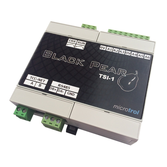
RBC-TSI1 Versatile Interface Installation Manual Product Description The RBC-TSI1 is a versatile interface for Toshiba air conditioning units, offering a wide range of external control facilities. The unit attaches to the TCC-NET A+B network. The interface is network powered and may be used with or without a remote controller being present. -
Page 8: Mechanical Data
RBC-TSI1 Versatile Interface Installation Manual Mechanical Data CAUTION w Do not exceed the specified fault relay ratings w Observe precautions for handling electrostatic sensitive devices 32mm... -
Page 9: Wiring Information
RBC-TSI1 Versatile Interface Installation Manual Wiring Information CAUTION All electrical work should be carried out by a competent person w and wiring must be in accordance with the national electrical installation regulations. Analogue Run Relay Inputs 24v 0.1A Error Relay 24v 0.1A Configuration Switches... -
Page 10: Appendix A: - Definitions
RBC-TSI1 Versatile Interface Installation Manual Appendix A: - Definitions The following nomenclature is used throughout this document. Modbus Holding Registers H-nn: These are the function 3/6/16 registers with offset nn. They are the same as registers 40000 + nn + 1 Function 3 is used to read the registers Functions 6 and 16 may be used to send values to them. -
Page 11: Appendix B: - Operating Modes
RBC-TSI1 Versatile Interface Installation Manual Appendix B: - Operating Modes B1: Standard Mode Master Unit Using A1 to A6 Using H-51 to H-55 and A5 1 2 3 4 5 6 7 8 1 2 3 4 5 6 7 8 Switch Settings: S1-2: Voltage or resistance inputs for A1 to A6 Resistance... - Page 12 RBC-TSI1 Versatile Interface Installation Manual Slave Unit Switch Settings: Using A1 to A6 Using H-51 to H-55 and A5 1 2 3 4 5 6 7 8 1 2 3 4 5 6 7 8 S1-2: Voltage or resistance inputs for A1 to A6 Resistance (for A5 active means linked to 0v) Voltage...
-
Page 13: B2: Pre-Set Slave Unit
RBC-TSI1 Versatile Interface Installation Manual B2: Pre-Set Slave Unit 1 2 3 4 5 6 7 8 Switch Settings: S1-2 &S1-3: Pre Set Mode S1-2 Off S1-3 Off Unlocked S1-2 Off S1-3 On Heat S1-2 On S1-3 Off Cool S1-2 On S1-3 On Auto S1-7 &... -
Page 14: B3: Standard Slave With Local/Restore
RBC-TSI1 Versatile Interface Installation Manual B3: Standard Slave with Local/Restore: Using A1 to A6 Using H-51 to H-55 and A5 1 2 3 4 5 6 7 8 1 2 3 4 5 6 7 8 Switch Settings: S1-2: Voltage or resistance inputs for A1 to A6 Resistance (for A5 active means linked to 0v) Voltage... -
Page 15: B4: Duty/Standby
RBC-TSI1 Versatile Interface Installation Manual B4: Duty/Standby Pre-Set Master Unit 1 2 3 4 5 6 7 8 For Duty / Standby mode the Master and Slave units must have an RS485 interconnection between them. Connect DB+ to DB+, DB- to DB- and COM to COM. Switch Settings S1-2 &... - Page 16 RBC-TSI1 Versatile Interface Installation Manual Duty/Standby Slave 1 2 3 4 5 6 7 8 The Duty/Standby Slave unit operate with the same parameter values as it associated Master unit. Should the Master unit stop sending values or go into error then the Slave unit will operate full time and an error condition will be generated...
-
Page 17: B5: Eco Timed Fan Mode
RBC-TSI1 Versatile Interface Installation Manual B5: Eco Timed Fan Mode Using A1 to A6 Using H-51 to H-54, A5 & A6 1 2 3 4 5 6 7 8 1 2 3 4 5 6 7 8 Switch Settings: S1-2: Voltage or resistance inputs for A1 to A6 Resistance (for A5 &... -
Page 18: B6: Eco Fan Band Mode
RBC-TSI1 Versatile Interface Installation Manual B6: Eco Fan Band Mode: Using A1 to A5 Using H-51 to H-54, A5 1 2 3 4 5 6 7 8 1 2 3 4 5 6 7 8 Switch Settings: S1-2: Voltage or resistance inputs for A1 to A5 Resistance (for A5 active means linked to 0v) Voltage... -
Page 19: B7: Hotel Controller Mode
RBC-TSI1 Versatile Interface Installation Manual B7: Hotel Controller Mode: Using A1 to Using H-51 to H-59, A5 & 1 2 3 4 5 6 7 8 1 2 3 4 5 6 7 8 Switch Settings: S1-2: Voltage or resistance inputs for A1 to A6 Resistance (for A5 &... -
Page 20: B8: Vn Unit
RBC-TSI1 Versatile Interface Installation Manual B8: VN Unit Note: VN units and standard fan coils cannot be mixed on the same RBC-TSI1 or on Master/Slave groups of RBC- TSI1 units. Master Unit Using A1 to A6 Using H-51 to H-55 and A5 1 2 3 4 5 6 7 8 1 2 3 4 5 6 7 8 Switch Settings:... - Page 21 RBC-TSI1 Versatile Interface Installation Manual VN Unit as Slave Using A1 to A6 Using H-51 to H-55 and A5 1 2 3 4 5 6 7 8 1 2 3 4 5 6 7 8 Switch Settings: S1-2: Voltage or resistance inputs for A1 to A6 Resistance (for A5 active means linked to 0v) Voltage (for A5 active means supplied with >...
-
Page 22: B9: Ahu Mode
RBC-TSI1 Versatile Interface Installation Manual B9: AHU Mode 1 2 3 4 5 6 7 8 The AHU mode only supports a single Air Handling Unit. Switch Settings S1-2 Off Full Demand Control S1-2 On 0-10V Input Control S1-7 & S1-8 : Modbus Address S1-7 Off S1-8 Off = Invalid for AHU mode. - Page 23 RBC-TSI1 Versatile Interface Installation Manual Relays: Relay 1 closes on defrost. Relay 2 closes on any fault. Modbus: The Modbus registers H0001, H0003 and H0005 have different functions in AHU mode as below. H0001 : Demand level (when SW1-2 is On) 0 to 1500 representing 0 to 15 power level.
-
Page 24: Appendix C: - Analogue Inputs
RBC-TSI1 Versatile Interface Installation Manual Appendix C: - Analogue Inputs Analogue Input Settings Set point, Lo-Set point, Hi_Set point, [Un]Occ SP, Occ SP Min, Occ SP Max Resistance KΩ <=0.4 >200 Voltage V <1.0 SP (deg C) Mode, Fan Speed, Air Direction, [Un]Occ MD, Occ Fan speed, VN Mode,VN Fan speed, Lock Resistance KΩ... -
Page 25: Appendix D: - Modbus
RBC-TSI1 Versatile Interface Installation Manual Appendix D: - Modbus Default serial parameters for the TSI-1 are 9600 baud, 8-bit, No parity, 1 Stop bit. Options for different baud rates and parity are available in configuration register C0 (See Appendix G) Input Registers Register Units... - Page 26 RBC-TSI1 Versatile Interface Installation Manual Holding Registers Register Units Description H0001 Deg C Set point (Deg C)*** H0002 0..3 Fan Speed H0003 0..4 Mode*** H0004 0..7 Louvre H0005 0..1 On/Off H0010 0..3 Update Mode (Global**) H0011 0..3 Update Mode (Set Point) H0012 0..3 Update Mode (Fan Speed)
- Page 27 RBC-TSI1 Versatile Interface Installation Manual Additional Functions Available via Modbus Lock Modes: Input A6 (H-56) provides a facility to set combinations of update modes for the parameters as ‘Locked’ or ‘Unlocked’. If the A6 setting for any parameter is ‘Unlocked’ then it is possible via Modbus to change that setting to ‘Locked’, ‘Local’, ‘Last Touch’...
-
Page 28: Appendix E: - Faults Codes
RBC-TSI1 Versatile Interface Installation Manual Appendix E: - Fault Codes Fault Codes: Toshiba fault codes are designated with a single letter followed by a decimal value in the range 01 to 15. The fault code values returned by the RBC-TSI1 may be converted into the equivalent Toshiba code as follows:- 1. -
Page 29: Appendix F:- Led Information
RBC-TSI1 Versatile Interface Installation Manual Appendix F:- LED Information LED Indications ‘ON’ (Amber):- Indicates that the unit is running. ‘ERR’ (Amber):- Indicates that the unit is in error. ‘HVAC’ (Green):- Flashes briefly on receipt of a message from the Air Conditioner ‘485’... -
Page 30: Appendix G:- Configuration Registers
RBC-TSI1 Versatile Interface Installation Manual Appendix G:- Configuration Registers The RBC-TSI1 has eight configuration registers referred to as C0 to C7 Each register holds a value between 0 and 15. The values held in the configuration registers may be viewed and altered by Using the configuration routine below. In addition, the values held in C0 to C7 may be viewed in Modbus registers I-05 to I-12 Register Functions: Sets the baud rate and parity for the RS485 link. - Page 31 RBC-TSI1 Versatile Interface Installation Manual Configuration settings:...
- Page 32 RBC-TSI1 Versatile Interface Installation Manual C5 & C6 Set to specify the secondary Modbus address (= 16xC5 + C6). Secondary address selected by switching S1-7 ON Perform Factory Reset...
-
Page 33: Appendix H: - Firmware Upgrade
RBC-TSI1 Versatile Interface Installation Manual Appendix H: - Firmware Upgrade Firmware Upgrade. Upgrading of the firmware requires a serial RS485 connection to the unit. This link must be capable of supporting 115,200 Baud. The procedure for upgrade is as follows: Download the revised firmware upgrade ‘BP_TSI1_FWnnn.exe’... -
Page 34: Appendix J: - Setting The Modbus Slave Address
RBC-TSI1 Versatile Interface Installation Manual Appendix J: - Setting the Modbus Slave Address The switches on the 8-Way bit switch are referred to as S1 to S8 address 1 Simple route to set Modbus For Address 1 Set S7 OFF and S8 ON These settings will always give slave address 1 2. - Page 35 RBC-TSI1 Versatile Interface Installation Manual Table 1 C5 and C6 values to set a Modbus Slave Address...
- Page 36 RBC-TSI1 Versatile Interface Installation Manual Table 2 Bit Switch Settings to Select Configuration Registers (0 = OFF, 1 = ON) Register Table 3 Bit Switch Settings to Set Register Values (0 = OFF, 1 = ON) Value...
- Page 37 RBC-TSI1 Versatile Interface Installation Manual Table 4 Reading the Configuration Register Values with the LEDs LEDs shown Left to Right 1 = Illuminated, 0 = Extinguished HVAC Value (Green) (Red) (Blue) (Amber) (Green) Flashing Flashing Flashing Flashing Flashing Flashing Flashing Flashing Flashing Flashing...
-
Page 38: Appendix K: - Revision History
RBC-TSI1 Versatile Interface Installation Manual Appendix K:- Revision History Date Document Ver Firmware Ver Comments 24/05/2016 v1.00 v1.19 First version 16/09/2016 v1.01 v1.24 Added AHU Mode Changed decals for link S2 Modified description of ECO Timed Fan Mode 26/10/2016 V1.02 V1.30 Revised description of ‘Hotel’... - Page 39 RBC-TSI1 Versatile Interface Installation Manual...
- Page 40 RBC-TSI1 Versatile Interface Installation Manual Fault code diagnosis apps now available Apple iPhone & Android 24 Hour Technical Helpline: 0870 843 0333 Fault & DN Code Apps: Android & iPhone Web Page toshiba-calc.co.uk/fault-codes/ Fault Code Text Service: 07624 803 017 technical.enquiries@toshiba-ac.com Technical Department AIR CONDITIONING...
Need help?
Do you have a question about the Black Pear RBC-TSI1 and is the answer not in the manual?
Questions and answers