Advertisement
Operating and Installation Instructions
CONTENTS
Operation in explosion-proof areas .......................................................................................
Technical data
Usage of the magnetic ball lifters
Hints for assembly
Troubleshooting
Spare part list
Exploded view
Dimensions
Accessories
ALMATEC Series
B I O C O R
B 20 / B 32
.......................................................................................
.......................................................................................
.......................................................................................
.......................................................................................
.........................................................................
.......................................................................................
.......................................................................................
.......................................................................................
.......................................................................................
.......................................................................................
.......................................................................................
.......................................................................................
.......................................................................................
.........................................................................
ought to be studied before
installing the pump
PAGE
2
3
3
3
4
6
6
6
7
8
10
12
13
14
15
Advertisement
Table of Contents

Related Manuals for Dover Almatec Biocor Series


Summary of Contents for Dover Almatec Biocor Series
-
Page 1: Table Of Contents
Operating and Installation Instructions ALMATEC Series B I O C O R B 20 / B 32 ought to be studied before installing the pump CONTENTS PAGE Introduction ..................Operation in explosion-proof areas ..................Technical data ..................Performance curves ..................Installation and operation .................. -
Page 2: Introduction
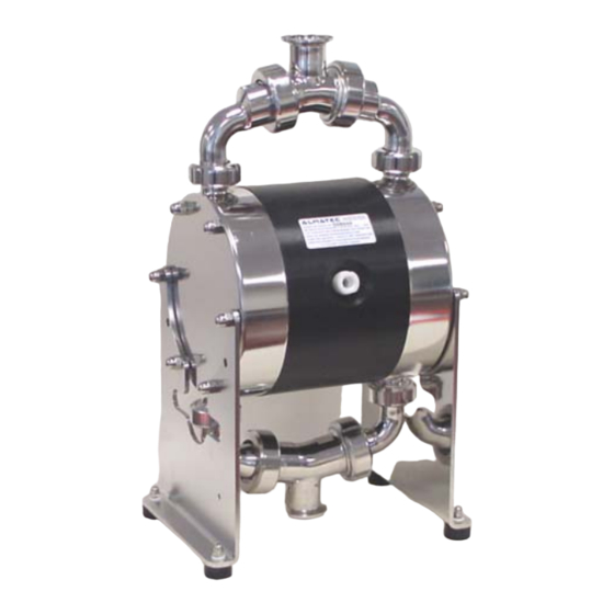
Introduction The ALMATEC Maschinenbau GmbH is certified as a modern, quality-orientated enterprise according to DIN EN ISO 9001:2000. Before release for dispatch, any BIOCOR pump has to undergo an extended final control. The performance data registered during this are archived in our records and can be read back at any time. -
Page 3: Performance Curves
Technical data B 20 B 32 Dimensions (mm): length width page page height Nominal port size (please see page 12) Air connection R 1/4“ R 1/4“ Weight (kg) Max. particle size of solids (mm) Suction lift, dry (mWC) Suction lift, wet (mWC) Max. -
Page 4: Installation And Operation
Recommended installation Installation and operation In general, the pump has to be connected load free. Neglecting this causes leakage and maybe even damages. To avoid vibrations, pulsation dampers and compensators are recommended. Before connecting the pump, take the yellow blind plugs out of the suction and discharge connections [4,6] as well as the air inlet [23]. - Page 5 premature wear. The maximum permissible stroke frequencies can be found in the following table. The pumps can briefly (up to max. one hour) be operated against a closed discharge line. Throttling on the suction side may damage the pump. Pump size B 20 B 32 Max.
-
Page 6: 3-A Approval
3-A approval BIOCOR pumps with the material combination 2 or 4 equipped with the option D (diaphragm monitoring, see page 14) are 3-A approved. Please pay attention to the following additional hints: • The pump has to be installed with a minimum distance of 100 mm between the floor and the suction port and 50 mm between the floor and the frame. -
Page 7: Disassembly
Disassembly The general design of the ALMATEC BIOCOR pumps is simple. A plastic tool designed for the mounting of the air-valve [22] is delivered along with every pump. Further special tools are not required. Please find the part number for any part in the spare part list. •... - Page 8 Dimensions (in mm) B 20 R 1/4“ B 32 17,5 R 1/4“ Code A Code M Code N1 Code N2 Code T (DIN 11864) (DIN 11851) Rd 44 x 1/6“ Rd 44 x 1/6“ M 36 x 2 M 36 x 2 1“...
- Page 9 Optional equipment For special requirements ALMATEC pneumatic double diaphragm pump of the series BIOCOR can be furnished with several optional equipments. The pump code informs, which of these are included in the pump (see page 2). Stroke counting (option code C) A sensor integrated in the center block [20] of the pump to monitor the movement of a diaphragm [15] without direct contact.
- Page 10 Barrier system (option code B) To comply with high safety standards, the barrier system replaces the standard diaphragm [15] by a tandem arrangement of two diaphragms [15,46] and a barrier chamber [40] of transparent PMMA filled with a non- conductive liquid (De-ionised water) in between. To ensure the correct operation of the pump, the barrier chambers [40] have to be filled completely.
Need help?
Do you have a question about the Almatec Biocor Series and is the answer not in the manual?
Questions and answers