Siemens SIMATIC S7-1500R/H Manual
Cpu 1515r-2 pn (6es7515-2rm00-0ab0)
Hide thumbs
Also See for SIMATIC S7-1500R/H:
- Getting started (52 pages) ,
- Equipment manual (48 pages) ,
- Manual (46 pages)
Table of Contents
Advertisement
Advertisement
Table of Contents

Related Manuals for Siemens SIMATIC S7-1500R/H


Summary of Contents for Siemens SIMATIC S7-1500R/H
- Page 2 ___________________ Preface ___________________ Documentation guide ___________________ SIMATIC Product overview ___________________ Connecting S7-1500R/H CPU 1515R-2 PN Interrupts, diagnostics, error ___________ messages and system (6ES7515-2RM00-0AB0) events ___________________ Manual Technical specifications ___________________ Dimension drawing 10/2018 A5E42009914-AA...
- Page 3 Note the following: WARNING Siemens products may only be used for the applications described in the catalog and in the relevant technical documentation. If products and components from other manufacturers are used, these must be recommended or approved by Siemens. Proper transport, storage, installation, assembly, commissioning, operation and maintenance are required to ensure that the products operate safely and without any problems.
-
Page 4: Preface
Preface Purpose of the documentation This manual supplements the system manual of the S7-1500R/H redundant system and the function manuals. This manual contains a description of the module-specific information. The system-related functions are described in the system manual. All system-spanning functions are described in the function manuals. - Page 5 Siemens' products and solutions undergo continuous development to make them more secure. Siemens strongly recommends that product updates are applied as soon as they are available and that the latest product versions are used. Use of product versions that are no longer supported, and failure to apply the latest updates may increase customers' exposure to cyber threats.
- Page 6 Preface Industry Mall The Industry Mall is the catalog and order system of Siemens AG for automation and drive solutions on the basis of Totally Integrated Automation (TIA) and Totally Integrated Power (TIP). You can find catalogs for all automation and drive products on the Internet (https://mall.industry.siemens.com).
-
Page 7: Table Of Contents
Table of contents Preface ..............................3 Documentation guide ..........................7 Product overview ..........................10 Configuration and operating principle ..................10 Hardware properties ......................12 Firmware functions ......................... 15 Operator controls and display elements ................17 2.4.1 Front view of the module with front panel ................17 2.4.2 Front view of the module without front panel ................. -
Page 8: Documentation Guide
S7-1500R/H system, e.g. diagnostics, communication. You can download the documentation free of charge from the Internet (https://support.industry.siemens.com/cs/ww/en/view/109742691). Changes and supplements to the manuals are documented in a Product Information. You can download the product information free of charge from the Internet (https://support.industry.siemens.com/cs/ww/en/view/109742691). - Page 9 You must register once to use the full functionality of "mySupport". You can find "mySupport" on the Internet (https://support.industry.siemens.com/My/ww/en/). "mySupport" - Documentation In the Documentation area in "mySupport" you can combine entire manuals or only parts of these to your own manual.
- Page 10 You can find SIEMENS PRONETA on the Internet (https://support.industry.siemens.com/cs/ww/en/view/67460624). SINETPLAN SINETPLAN, the Siemens Network Planner, supports you in planning automation systems and networks based on PROFINET. The tool facilitates professional and predictive dimensioning of your PROFINET installation as early as in the planning stage. In addition, SINETPLAN supports you during network optimization and helps you to exploit network resources optimally and to plan reserves.
-
Page 11: Product Overview
Product overview Configuration and operating principle Structure The S7-1500R redundant system consists of the following components: ● Two CPUs of the type CPU 1515R-2 PN ● Two SIMATIC memory cards ● PROFINET cable (PROFINET ring) ● IO devices ● Load power supply (optional) ●... - Page 12 The redundancy connections are the PROFINET ring with MRP. The CPUs are synchronized via a PROFINET ring. Reference You can find a detailed description of the operation and design of the CPUs in the system manual Redundant System S7-1500R/H (https://support.industry.siemens.com/cs/ww/en/view/109754833). CPU 1515R-2 PN (6ES7515-2RM00-0AB0) Manual, 10/2018, A5E42009914-AA...
-
Page 13: Hardware Properties
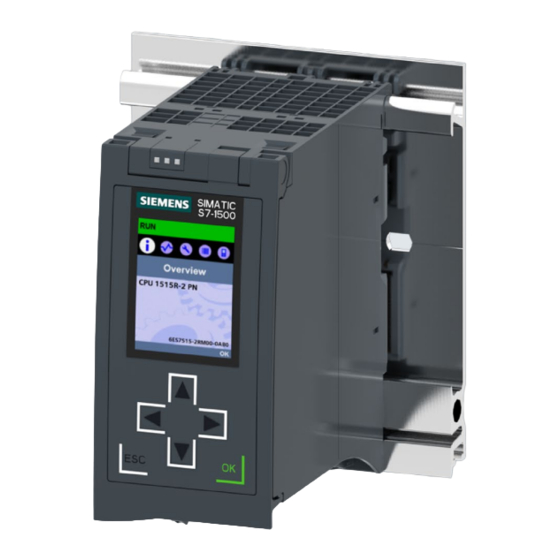
Product overview 2.2 Hardware properties Hardware properties Article number 6ES7515-2RM00-0AB0 View of the module The figure below shows the CPU 1515R-2 PN. Figure 2-2 CPU 1515R-2 PN Note Protective film Note that there is a removable protective foil on the display when the CPUs are delivered. CPU 1515R-2 PN (6ES7515-2RM00-0AB0) Manual, 10/2018, A5E42009914-AA... - Page 14 All CPUs of the redundant system S7 1500R/H have a Redundant System S7-1500R/H • display with plain text information. The display provides (https://support.industry.siemens. you with diagnostic messages as well as information com/cs/ww/en/view/109754833) about the article number, the firmware version and the System Manual serial number of the CPU.
- Page 15 The CPU has an X1 interface with two ports (X1 P1 R Redundant System S7-1500R/H • (X1 P1 R and X1 P2 R) and X1 P2 R). (https://support.industry.siemens. com/cs/ww/en/view/109754833) The PROFINET IO interface X1 (default P1 R) is • System Manual used to set up the PROFINET ring with the two CPUs and the IO devices.
-
Page 16: Firmware Functions
CPU redundancy There are two duplicate CPUs that synchronize their Redundant System S7-1500R/H data via redundancy connections within a PROFINET (https://support.industry.siemens.co ring. If one of the CPUs fails, the other CPU retains m/cs/ww/en/view/109754833) Sys- control of the process. tem Manual... - Page 17 The PROFINET device itself only contributes a few watts to the savings potential. Integrated technology Integrated closed-loop The CPUs support PID basic functions. Function manual PID Control control functionality (https://support.industry.siemens.co No controller support: m/cs/ww/en/view/108210036) PID_Compact • PID _3Step • PID_Temp •...
-
Page 18: Operator Controls And Display Elements
Product overview 2.4 Operator controls and display elements Operator controls and display elements 2.4.1 Front view of the module with front panel The figure below shows the front view of the CPU 1515R-2 PN. ① LEDs for the current operating state and diagnostic status of the CPU ②... - Page 19 (local lock) and assign a password for the display. You can find additional information on the display, the configurable protection levels and the local lock in the system manual for Redundant System S7-1500R/H (https://support.industry.siemens.com/cs/ww/en/view/109754833). Reference You can find detailed information on the individual display options, a training course and a simulation of the available menu commands in the SIMATIC S7-1500 Display Simulator (http://www.automation.siemens.com/salesmaterial-as/interactive-manuals/getting-...
-
Page 20: Front View Of The Module Without Front Panel
Product overview 2.4 Operator controls and display elements 2.4.2 Front view of the module without front panel The figure below shows the operator controls and connection elements of the CPU 1515R-2 PN. ① LEDs for the current operating state and diagnostic status of the CPUs ②... -
Page 21: Rear View Of The Module
Product overview 2.4 Operator controls and display elements 2.4.3 Rear view of the module The figure below shows the connection elements on the rear of the CPU 1515R-2 PN. ① Shield contact surfaces ② Plug-in connection for power supply ③ Plug-in connection for backplane bus ④... -
Page 22: Mode Selector
You can find a brief overview of the various operating states and system states in the section Status and error display of the CPU (Page 26). You can find a detailed description of the operating states and system states in the system manual for S7-1500R/H Redundant System (https://support.industry.siemens.com/cs/ww/en/view/109754833). CPU 1515R-2 PN (6ES7515-2RM00-0AB0) Manual, 10/2018, A5E42009914-AA... -
Page 23: Connecting
Spring opener (one spring opener per terminal) Bridged internally: ① ④ ② ③ Figure 3-1 Supply voltage connection You can find information on the various supply options in the system manual for Redundant System S7-1500R/H (https://support.industry.siemens.com/cs/ww/en/view/109754833). CPU 1515R-2 PN (6ES7515-2RM00-0AB0) Manual, 10/2018, A5E42009914-AA... - Page 24 (MDI) or a switch (MDI-X). Reference You can find additional information on the topic of "Connecting the CPU" and on the topic "Accessories/spare parts" in the system manual for Redundant System S7-1500R/H (https://support.industry.siemens.com/cs/ww/en/view/109754833). CPU 1515R-2 PN (6ES7515-2RM00-0AB0) Manual, 10/2018, A5E42009914-AA...
- Page 25 Connecting 3.1 Terminal assignment Assignment of the MAC addresses For each CPU, CPU 1515R-2 PN has: ● One PROFINET interface with two ports ● One PROFINET interface with one port Each of the PROFINET interfaces has a MAC address and each of the PROFINET ports has its own MAC address.
- Page 26 Connecting 3.1 Terminal assignment Block diagram The following figure shows the block diagram of the CPU 1515R-2 PN. ① SIMATIC memory card (X50) PN X1 P2 R PROFINET interface X1 port 2 ② Display PN X2 P1 PROFINET interface X2 port 1 ③...
-
Page 27: Interrupts, Diagnostics, Error Messages And System Events
You can find more detailed information on "Interrupts" in the STEP 7 online help. You can find additional information on the topic of "Diagnostics" and "System events" in the Diagnostics (http://support.automation.siemens.com/WW/view/en/59192926) function manual and in the system manual Redundant System S7-1500R/H (https://support.industry.siemens.com/cs/ww/en/view/109754833). - Page 28 Interrupts, diagnostics, error messages and system events 4.1 Status and error display of the CPU LED displays depending on operating states and system states CPU 1515R-2 PN has the following LEDs for displaying the current operating state and diagnostics status. ●...
- Page 29 Interrupts, diagnostics, error messages and system events 4.1 Status and error display of the CPU Meaning of the RUN/STOP, ERROR and MAINT LEDs CPU 1515R-2 PN has the following LEDs for displaying the current operating state and diagnostics status. Note LED patterns of the redundant system S7 1500R Note that it is not always possible to: •...
- Page 30 Interrupts, diagnostics, error messages and system events 4.1 Status and error display of the CPU The following table shows the meaning of the various color combinations for the RUN/STOP, ERROR and MAINT LEDs. Table 4- 1 Meaning of the LEDs RUN/STOP LED ERROR LED MAINT LED...
- Page 31 Interrupts, diagnostics, error messages and system events 4.1 Status and error display of the CPU Note MAINT LED of the two CPUs The MAINT LEDs of both CPUs only go out when the following conditions are fulfilled: • The CPUs are in the RUN-Redundant system state. •...
-
Page 32: Technical Specifications
Technical specifications General technical specifications Article number 6ES7515-2RM00-0AB0 General information Product type designation CPU 1515R-2 PN HW functional status FS01 Firmware version V2.6 Engineering with STEP 7 V15.1 or higher STEP 7 TIA Portal configurable/integrated • as of version Display Screen diagonal [cm] 6.1 cm Control elements... - Page 33 Technical specifications Article number 6ES7515-2RM00-0AB0 Backup maintenance-free • CPU processing times for bit operations, typ. 60 ns for word operations, typ. 72 ns for fixed point arithmetic, typ. 96 ns for floating point arithmetic, typ. 384 ns CPU-blocks Number of elements (total) 6 000;...
- Page 34 Technical specifications Article number 6ES7515-2RM00-0AB0 IEC counter Any (only limited by the main memory) Number • Retentivity – adjustable S7 times 2 048 Number • Retentivity – adjustable IEC timer Any (only limited by the main memory) Number • Retentivity –...
- Page 35 Technical specifications Article number 6ES7515-2RM00-0AB0 Time of day Clock 6 wk; At 40 °C ambient temperature, typically Backup time • 10 s; Typ.: 2 s Deviation per day, max. • Operating hours counter Number • Clock synchronization supported • in AS, master •...
- Page 36 Technical specifications Article number 6ES7515-2RM00-0AB0 PROFINET IO Controller Services – PG/OP communication – S7 routing – Isochronous mode – Open IE communication – Yes; Only Manager Auto, max. 50 nodes; only 16 – are recommended, however – MRPD – PROFIenergy –...
- Page 37 Technical specifications Article number 6ES7515-2RM00-0AB0 Protocols Number of connections Number of connections, max. • Number of connections reserved for • ES/HMI/web Redundancy mode Yes; Manager Auto is permanently set in TIA. • Max. 50 nodes are possible, 16 are recommend- MRPD •...
- Page 38 Technical specifications Article number 6ES7515-2RM00-0AB0 S7 message functions Program alarms Test commissioning functions Joint commission (Team Engineering) Status block Yes; up to 8 simultaneously Single step Status/control Status/control variable • Inputs/outputs, memory bits, DBs, distributed Variables • I/Os, timers, counters Number of variables, max.
- Page 39 Technical specifications Article number 6ES7515-2RM00-0AB0 Standards, approvals, certificates Suitable for safety functions Ambient conditions Ambient temperature during operation 0 °C horizontal installation, min. • 60 °C; Display: 50 °C, at an operating tempera- horizontal installation, max. • ture of typically 50 °C, the display is switched off 0 °C vertical installation, min.
- Page 40 You can find information on the general technical specifications, such as standards and approvals, electromagnetic compatibility, protection class, etc. in the system manual for Redundant System S7-1500R/H. See also S7-1500R/H Redundant System (https://support.industry.siemens.com/cs/ww/en/view/109754833) CPU 1515R-2 PN (6ES7515-2RM00-0AB0) Manual, 10/2018, A5E42009914-AA...
-
Page 41: A Dimension Drawing
Dimension drawing Dimension drawing This section contains the dimensional drawing of the module on the mounting rail, as well as a dimensional drawing with the front panel open. Keep to the dimensions when installing in cabinets, control rooms, etc. Dimension drawings of the CPU 1515R-2 PN Figure A-1 Dimension drawing of the CPU 1515R-2 PN, front and side view CPU 1515R-2 PN (6ES7515-2RM00-0AB0) - Page 42 Dimension drawing A.1 Dimension drawing Figure A-2 Dimension drawing CPU 1515R-2 PN, side view with open front panel CPU 1515R-2 PN (6ES7515-2RM00-0AB0) Manual, 10/2018, A5E42009914-AA...
Need help?
Do you have a question about the SIMATIC S7-1500R/H and is the answer not in the manual?
Questions and answers