Table of Contents
Advertisement
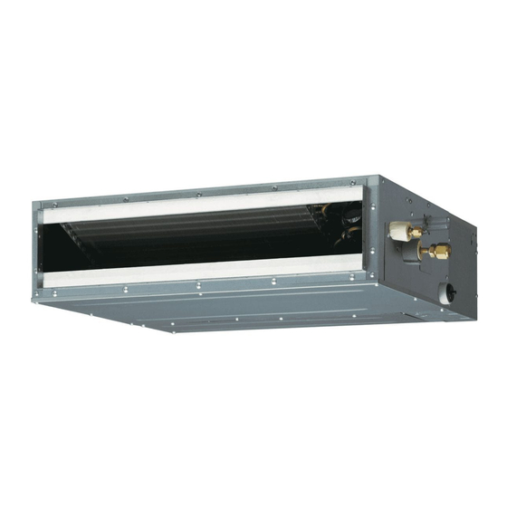
AIR CONDITIONER
Duct type
Contents
1.
SAFETY PRECAUTIONS .................................................................. 1
1.1. Precautions for using R32 refrigerant ......................................... 2
2.
PRODUCT SPECIFICATION ............................................................. 4
2.1. Installation tools .......................................................................... 4
2.2. Accessories ................................................................................ 4
2.3. Pipe requirement ........................................................................ 4
2.4. Electrical requirement ................................................................. 4
2.5. Optional parts ............................................................................. 5
3.
INSTALLATION WORK ..................................................................... 5
3.1. Selecting an installation location ................................................ 5
3.2. Installation dimensions ............................................................... 5
3.3. Installing the unit ......................................................................... 5
3.4. Drain installation ......................................................................... 7
3.5. Pipe installation .......................................................................... 9
3.6. Electrical wiring ......................................................................... 10
3.7. Remote controller setting .......................................................... 13
4.
OPTIONAL INSTALLATION WORK ................................................ 13
4.1. Optional kit installation .............................................................. 13
4.2. External input and output .......................................................... 13
4.3. Remote sensor (Optional parts) ............................................... 14
4.4. IR receiver unit (Optional parts) ................................................ 14
4.5. Auto louver grille (Optional parts) ............................................. 14
4.6. Other optional parts .................................................................. 14
4.7. Optional parts cable binding ..................................................... 15
5.
REMOTE CONTROL INSTALLATION ............................................. 15
5.1. Group control ............................................................................ 15
5.2. Multiple remote control ............................................................. 16
5.3. DIP switch 101 setting .............................................................. 16
5.4. Simultaneous multi-system operation ....................................... 17
6.
FUNCTION SETTING...................................................................... 17
6.1. Function details ........................................................................ 17
7.
TEST RUN ....................................................................................... 19
7.1. Check items .............................................................................. 19
7.2. Operation method ..................................................................... 19
8.
FINISHING ...................................................................................... 19
9.
CUSTOMER GUIDANCE ................................................................ 19
10. ERROR CODES .............................................................................. 19
NOTES: This manual describes how to install the air conditioner described above. Handling
and installation shall only be done by professionals as outlined in this manual.
1. SAFETY PRECAUTIONS
• Be sure to read this manual thoroughly before installation.
• The warnings and precautions indicated in this manual contain important information
pertaining to your safety. Be sure to observe them.
• Hand this manual, together with the operating manual, to the customer. Request the
customer to keep them on hand for future use, such as for relocating or repairing the
unit.
Indicates a potentially or imminently hazardous situation
WARNING
which, if not avoided, could result in death or serious injury.
Indicates a potentially hazardous situation that may result in
CAUTION
minor or moderate injury or damage to property.
INSTALLATION MANUAL
[Original instructions]
• The appliance shall be installed, operated and stored in a room with a fl oor area larger
than X m².
Amount of refrigerant charge
M (kg)
M ≤ 1.22
1.22 < M ≤ 1.23
1.23 < M ≤ 1.50
1.50 < M ≤ 1.75
1.75 < M ≤ 2.0
2.0 < M ≤ 2.5
2.5 < M ≤ 3.0
3.0 < M ≤ 3.5
3.5 < M ≤ 4.0
• Installation of this product must be done by experienced service technicians or profes-
sional installers only in accordance with this manual. Installation by non-professional
or improper installation of the product might cause serious accidents such as injury,
water leakage, electric shock, or fi re. If the product is installed in disregard of the
instructions in this manual, it will void the manufacturer's warranty.
• Do not turn on the power until all work has been completed. Turning on the power be-
fore the work is completed can cause serious accidents such as electric shock or fi re.
• If refrigerant leaks when you are working, ventilate the area. If the leaking refrigerant
is exposed to a direct fl ame, it may produce a toxic gas.
• Installation must be performed in accordance with regulations, codes, or standards for
electrical wiring and equipment in each country, region, or the installation place.
• Do not use means to accelerate the defrosting process or to clean, other than those
recommended by the manufacturer.
• This appliance is not intended for use by persons (including children) with reduced
physical, sensory or mental capabilities, or lack of experience and knowledge, unless
they have been given supervision or instruction concerning use of the appliance by a
person responsible for their safety. Children should be supervised to ensure that they
do not play with the appliance.
• To avoid danger of suffocation, keep the plastic bag or thin fi lm used as the packaging
material away from young children.
• The appliance shall be stored in a room without continuously operating ignition
sources (for example: open fl ames, an operating gas appliance or an operating
electric heater).
• Do not pierce or burn.
• Be aware that refrigerants may not contain an odour.
• Read carefully all safety information written in this manual before you install or use the
air conditioner.
• Install the product by following local codes and regulations in force at the place of
installation, and the instructions provided by the manufacturer.
• This product is part of a set constituting an air conditioner. The product must not be
installed alone or be installed with a device not authorized by the manufacturer.
• Always use a separate power supply line protected by a circuit breaker operating on
all wires with a distance between contact of 3 mm for this product.
• To protect the persons, earth (ground) the product correctly, and use the power cable
combined with an Earth Leakage Circuit Breaker (ELCB).
• This product is not explosion proof, and therefore should not be installed in an explo-
sive atmosphere.
• To avoid getting an electric shock, never touch the electrical components soon after
the power supply has been turned off. After turning off the power, always wait 5 min-
utes or more before you touch the electrical components.
• This product contains no user-serviceable parts. Always consult experienced service
technicians for repairing.
• When moving or relocating the air conditioner, consult experienced service technicians
for disconnection and reinstallation of the product.
• Do not touch the aluminum fi ns of heat exchanger built-in the indoor or outdoor unit to
avoid personal injury when you install or maintain the unit.
• Do not place any other electrical products or household belongings under the product.
Condensation dripping from the product might get them wet, and may cause damage
or malfunction to the property.
• Be careful not to scratch the air conditioner when handling it.
PART No. 9374342532
For authorized service personnel only.
WARNING
Minimum room area
2
X (m
)
-
1.45
2.15
2.92
3.82
5.96
8.59
11.68
15.26
(IEC 60335-2-40)
CAUTION
En-1
Advertisement
Table of Contents

Related Manuals for Fujitsu ARXG-KLLAP Series


Summary of Contents for Fujitsu ARXG-KLLAP Series
-
Page 1: Table Of Contents
INSTALLATION MANUAL AIR CONDITIONER Duct type PART No. 9374342532 [Original instructions] For authorized service personnel only. WARNING • The appliance shall be installed, operated and stored in a room with a fl oor area larger than X m². Amount of refrigerant charge Minimum room area M (kg) X (m... -
Page 2: Precautions For Using R32 Refrigerant
1.1. Precautions for using R32 refrigerant CAUTION 2-5 No ignition sources The basic installation work procedures are the same as conventional refrigerant (R410A, • No person carrying out work in relation to a refrigeration system which involves R22) models. exposing any pipe work that contains or has contained fl ammable refrigerant shall However, pay careful attention to the following points: use any sources of ignition in such a manner that it may lead to the risk of fi... - Page 3 CAUTION CAUTION 5-Cabling 10-Decommissioning • Check that cabling will not be subject to wear, corrosion, excessive pressure, vibra- • Before carrying out this procedure, it is essential that the technician is completely tion, sharp edges or any other adverse environmental effects. familiar with the equipment and all its details.
-
Page 4: Product Specification
Coupler heat insulation (large) 2. PRODUCT SPECIFICATION Hose band 2.1. Installation tools Coupler heat insulation(small) Drain hose insulation B Tool name Change from R22 to R32 (R410A) Pressure is high and cannot be measured with a R22 gauge. To prevent erroneous mixing of other refrigerants, the diameter of each port has been changed. -
Page 5: Optional Parts
2.5. Optional parts 3.2. Installation dimensions Refer to each installation manual for the method of installing optional parts. Provide a Service access for inspection purposes. Do not place any wiring or illumination in the service space, as they will impede service. Parts name Model No. - Page 6 Outlet side CAUTION • Check that duct work does not exceed the range of external static pressure of equip- ment. • Make sure to insulate ducts to avoid the dew condensation. • Make sure to insulate between ducts and walls if metal ducts are used. •...
-
Page 7: Drain Installation
3.3.4. Fix the unit 3.4. Drain installation (1) Hang the unit Hanger 3.4.1. Installing drain pipes Hanger bolt WARNING Nut A • Do not insert the drain piping into the sewer where sulfurous gas occurs. (Heat ex- (Locally purchased) change erosion may occur) •... - Page 8 • Provide a downward gradient (1/100 or more). (2) Be sure to connect Drain pipe with adhesive (polyvinyl chloride) so that there is no • Provide supporters when long pipes are installed. leakage. • Use an insulation material as needed, to prevent the pipes from freezing. Applying •...
-
Page 9: Pipe Installation
• When drain pump is used. When using conventional fl are tools to fl are R32 pipes, the dimension A should be approx- imately 0.5 mm more than indicated in the table (for fl aring with R32 fl are tools) to achieve the specifi... -
Page 10: Electrical Wiring
3.6.1. Wiring system diagram 3.6. Electrical wiring ■ Standard pair Connection cable WARNING Indoor unit Outdoor unit Earth (Ground) line • Electrical work must be performed in accordance with this Manual by a person certifi ed Power line under the national or regional regulations. Be sure to use a dedicated circuit for the unit. - Page 11 ■ Simultaneous twin (18 model only) ■ Simultaneous triple (18 model only) Connection cable Connection cable Indoor unit Junction box (Locally purchased) Junction box (Locally purchased) Indoor unit (Primary) Earth (Ground) line Outdoor unit Earth (Ground) line (Primary) Outdoor unit Earth (Ground) line Earth (Ground) line Indoor unit...
- Page 12 ■ Connection cable 3.6.2. Connection cable preparation ■ Connection cable Keep the earth (ground) wire longer than the other wires. Connection cable Control line Earth (Ground) wire Power line Connection cable Outdoor • Use a 4-core wire cable. (power supply) unit Earth (ground) ■...
-
Page 13: Remote Controller Setting
(4) Seal the cable outlet or other gaps with putty to prevent dew condensation or insect Terminal from entering the electric control box. (5) Replace the control box cover. TO REMOTE CONTROL UNIT Ex IN CAUTION Do not bundle the remote controller cable, or wire the remote controller cable in par- allel, with the indoor unit connection wire (to the outdoor unit) and the power supply cable. -
Page 14: Remote Sensor (Optional Parts)
■Operation behavior 4.5. Auto louver grille (Optional parts) *If function setting “60” is set to “00” 4.5.1. Connection method • Wiring arrangement Function setting Status Output voltage Controller PCB Stop Operation DC 12 V Normal Error DC 12 V Indoor unit fan stop Indoor unit fan operation DC 12 V External heater OFF... -
Page 15: Optional Parts Cable Binding
(2) Set the R.C. address (DIP switch setting) 4.7. Optional parts cable binding Set the R.C. address of each indoor unit using the DIP switch on the indoor unit circuit board. Bushing** Insulation Air inlet Other optional parts cables Remote controller Cable tie cable (medium,... -
Page 16: Multiple Remote Control
■ Settings when simultaneous Multi is included 5.2. Multiple remote control (3) Set the refrigerant circuit address (Remote controller setting) 1. Turn on all of the indoor units. Up to 2 remote controllers can be used to operate one indoor unit * Turn on the indoor unit with the R.C. -
Page 17: Simultaneous Multi-System Operation
3. After completing the function settings, turn off all of the indoor units, and then turn 5.4. Simultaneous multi-system operation them back on. * If error code 21, 22, 24 or 27 is displayed, there may be an incorrect setting. Perform the remote controller setting again. - Page 18 ■ Room temperature control for indoor unit sensor ■ Remote controller custom code (Only for wireless remote controller) Depending on the installed environment, correction of the room temperature sensor may The indoor unit custom code can be changed. Select the appropriate custom code. be required.
-
Page 19: Test Run
7. TEST RUN 10. ERROR CODES If you use a wireless remote controller, the lamp on the photo detector unit will output error 7.1. Check items codes by way of blinking patterns. If you use a wired remote controller, error codes will ap- pear on the remote control display. - Page 20 Error display Error display OPERATION TIMER ECONOMY OPERATION TIMER ECONOMY Error code Description Error code Description lamp lamp lamp lamp lamp lamp (green) (orange) (green) (green) (orange) (green) Compressor rotor position Filter set error ● ● detection error (permanent stop) Damper error Outdoor unit fan motor 1 error ...
Need help?
Do you have a question about the ARXG-KLLAP Series and is the answer not in the manual?
Questions and answers