Table of Contents
Advertisement
AIR CONDITIONER
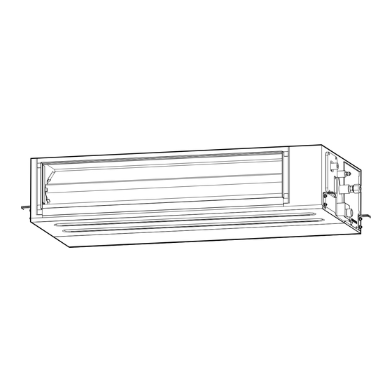
INDOOR UNIT (Duct type)
Contents
1. SAFETY PRECAUTIONS ...................................................... 1
2. PRODUCT SPECIFICATION ................................................... 4
2.1. Installation tools ............................................................ 4
2.2. Accessories .................................................................. 4
2.3. Pipe requirement ............................................................ 5
2.4. Electrical requirement ...................................................... 5
2.5. Optional parts ............................................................... 5
3. INSTALLATION WORK ......................................................... 5
3.1. Selecting an installation location ....................................... 5
3.2. Installation dimension ...................................................... 6
3.3. Installing the unit ............................................................ 6
3.4. Intake duct connection ................................................... 7
3.5. Drain installation ............................................................ 7
3.6. Pipe installation ............................................................ 8
3.7. Fresh air intake ............................................................... 9
3.8. Electrical wiring ......................................................... 10
3.9. Remote controller installation .......................................... 11
4. OPTIONAL INSTALLATION WORK ....................................... 11
4.1. Optional kit installation ................................................ 11
4.2. External input and output ............................................. 11
......................................................... 12
5. REMOTE CONTROL INSTALLATION .................................... 12
5.1. Group control ............................................................ 12
5.2. Multiple remote control ................................................ 13
5.3. DIP switch 101 setting ................................................... 13
6. FUNCTION SETTING ......................................................... 13
6.1. Function details ......................................................... 13
6.2. Static pressure ............................................................ 14
7. CHECK LIST ..................................................................... 15
8. TEST RUN ........................................................................ 15
8.1. Check items ............................................................... 15
8.2. Operation method ...................................................... 15
9. FINISHING ........................................................................ 15
10. CUSTOMER GUIDANCE ...................................................... 15
11. ERROR CODES ............................................................... 16
NOTE: This manual describes how to install the air conditioner described above. Handling
and installation shall only be done by professionals as outlined in this manual.
1. SAFETY PRECAUTIONS
• Be sure to read this manual thoroughly before installation.
• The warnings and precautions indicated in this manual contain important information
pertaining to your safety. Be sure to observe them.
• Hand this manual, together with the operating manual, to the customer. Request the
customer to keep them on hand for future use, such as for relocating or repairing the
unit.
INSTALLATION MANUAL
[Original instructions]
Indicates a potentially or imminently hazardous situation
WARNING
which, if not avoided, could result in death or serious injury.
Indicates a potentially hazardous situation that may result in
CAUTION
minor or moderate injury or damage to property.
• The appliance shall be installed, operated and stored in a room with a fl oor area larger
than X m².
Amount of refrigerant charge
M (kg)
M ≤ 1.22
1.22 < M ≤ 1.23
1.23 < M ≤ 1.50
1.50 < M ≤ 1.75
1.75 < M ≤ 2.0
2.0 < M ≤ 2.5
2.5 < M ≤ 3.0
3.0 < M ≤ 3.5
3.5 < M ≤ 4.0
• Installation of this product must be done by experienced service technicians or profes-
sional installers only in accordance with this manual. Installation by non-professional
or improper installation of the product might cause serious accidents such as injury,
water leakage, electric shock, or fi re. If the product is installed in disregard of the
instructions in this manual, it will void the manufacturer's warranty.
• Do not turn on the power until all work has been completed. Turning on the power be-
fore the work is completed can cause serious accidents such as electric shock or fi re.
• If refrigerant leaks when you are working, ventilate the area. If the leaking refrigerant
is exposed to a direct fl ame, it may produce a toxic gas.
• Installation must be performed in accordance with regulations, codes, or standards for
electrical wiring and equipment in each country, region, or the installation place.
• Do not use means to accelerate the defrosting process or to clean, other than those
recommended by the manufacturer.
• This appliance is not intended for use by persons (including children) with reduced
physical, sensory or mental capabilities, or lack of experience and knowledge, unless
they have been given supervision or instruction concerning use of the appliance by a
person responsible for their safety. Children should be supervised to ensure that they
do not play with the appliance.
• To avoid danger of suffocation, keep the plastic bag or thin fi lm used as the packaging
material away from young children.
• The appliance shall be stored in a room without continuously operating ignition
sources (for example: open fl ames, an operating gas appliance or an operating
electric heater).
• Do not pierce or burn.
• Be aware that refrigerants may not contain an odour.
PART No. 9381386215
For authorized service personnel only.
WARNING
Minimum room area
X (m
2
)
-
1.45
2.15
2.92
3.82
5.96
8.59
11.68
15.26
(IEC 60335-2-40)
En-1
Advertisement
Table of Contents

Related Manuals for Fujitsu ARXG-KHTAP Series


Summary of Contents for Fujitsu ARXG-KHTAP Series
-
Page 1: Table Of Contents
AIR CONDITIONER INSTALLATION MANUAL INDOOR UNIT (Duct type) PART No. 9381386215 [Original instructions] For authorized service personnel only. Indicates a potentially or imminently hazardous situation WARNING which, if not avoided, could result in death or serious injury. Indicates a potentially hazardous situation that may result in CAUTION minor or moderate injury or damage to property. -
Page 2: Iec 60335
CAUTION CAUTION • Read carefully all safety information written in this manual before you install or use the 2-Servicing air conditioner. 2-1 Service personnel • Install the product by following local codes and regulations in force at the place of •... - Page 3 CAUTION CAUTION 2-8 Checks to electrical devices 8-Removal and evacuation • Repair and maintenance to electrical components shall include initial safety checks • When breaking into the refrigerant circuit to make repairs – or for any other and component inspection procedures. purpose –conventional procedures shall be used.
-
Page 4: Product Specification
WARNING CAUTION 12-Recovery • Do not use the existing (for R22) piping and fl are nuts. If the existing materials are used, the pressure inside the refrigerant cycle will rise and • When removing refrigerant from a system, either for servicing or decommissioning, it is recommended good practice that all refrigerants are removed safely. -
Page 5: Pipe Requirement
2. 3. Pipe requirement External input and output For installing the External input UTZ-GXNA PCB bracket and output PCB External connect kit UTY-XWZXZG For control output port CAUTION LFNA : 36/45/54 model Air fi lter kit UTD-LFNA/B/C LFNB : 18/22/24/30 model Refer to the installation manual of the outdoor unit for description of the length of con- LFNC : 12/14 model necting pipe or for difference of its elevation. -
Page 6: Installation Dimension
3. 2. Installation dimension CAUTION Confi rm the directions of the air intake and outlet before installing the unit. The unit takes in air from the evaporator side, and expels it from the fan side. Unit: mm 3. 3. 1. Position the ceiling hole 20 or more Hanging bolt installation diagram. -
Page 7: Intake Duct Connection
CAUTION CAUTION Fasten the unit securely with special nuts A and B so that the unit does not fall. • Make sure the drain water is properly drained. • To prevent people from touching the parts inside the unit, be sure to install grilles on the inlet and outlet ports. -
Page 8: Pipe Installation
Hose band (Accessory) Drain hose insulation GOOD • When the pipe is long, install supporters. (Accessory) Outlet Drain hose insulation airfl ow (Accessory) Supporter Drain pipe Indoor unit Arrange the drain pipe lower than this portion 1.5 to 2 m Drain hose 100 mm Overlap the heat insulation. -
Page 9: Fresh Air Intake
3. 6. 1. Pipe connection CAUTION ■ Flaring • Hold the torque wrench at its grip, keeping it in the right angle with the pipe, in order Use special pipe cutter and fl are tool designed for R410A or R32 pipework. to tighten the fl... -
Page 10: Electrical Wiring
3. 8. 2. Connection cable preparation 3. 8. Electrical wiring ■ Connection cable WARNING Keep the earth (ground) wire longer than the other wires. • Electrical work must be performed in accordance with this Manual by a person certifi ed under the national or regional regulations. Be sure to use a dedicated circuit for the unit. -
Page 11: Remote Controller Installation
■ Connection cable 4. OPTIONAL INSTALLATION WORK 4. 1. Optional kit installation WARNING Regulation of cable differs from each locality, refer in accordance with local rules. Control line CN8 (Remote sensor) Power line Outdoor Connection cable unit Earth (ground) ■ Remote controller cable CN48 CN65 CN47... -
Page 12: Remote Sensor
When function setting is “Forced stop” mode. 4. 3. Remote sensor Input signal Command Remote sensor OFF → ON Forced stop • Remove the existing connector and replace it with the remote sensor connector (ensure that the correct connector is used). •... -
Page 13: Multiple Remote Control
Example If 4 indoor units are connected. 6. FUNCTION SETTING Indoor unit 1 Indoor unit 2 Indoor unit 3 Indoor unit 4 To change the function settings, refer to the procedures described in the installation RC AD SW RC AD SW RC AD SW RC AD SW manual of the remote controller (wired type). -
Page 14: Static Pressure
■ Auto restart ■ Switching functions for external output terminal Enable or disable automatic restart after a power interruption. Functions of the external output terminal can be switched. (♦... Factory setting) (♦... Factory setting) Function Setting Setting Setting Description Function Number Setting Description Number Value... -
Page 15: Check List
b. Automatic airfl ow adjustment 8. 2. Operation method Depending on your installation, choose from the following: CAUTION ■ By the wireless remote controller (with [TEST RUN] button) • This function cannot be used when there is a booster fan between the ducts. •... -
Page 16: Error Codes
11. ERROR CODES Error display Wired remote TIMER ECONOMY Description If you use a wired type remote controller, error codes will appear on the remote control- OPERATION controller lamp lamp ler display. If you use a wireless remote controller, the lamps on the IR receiver unit will lamp (green) Error code (orange)
Need help?
Do you have a question about the ARXG-KHTAP Series and is the answer not in the manual?
Questions and answers