
Related Manuals for Relay MR005DL

Summary of Contents for Relay MR005DL
- Page 1 M-Bus Display / Datalogger MR005FA / MR005DL MR006FA / MR006DL M-Bus Remote Displays and Datalogger for 3 or 20 Slaves User Manual...
-
Page 2: Table Of Contents
7 Additional functions of the Datalogger..................15 8 PC-Software FService......................16 9 Addendum ..........................17 9.1 Error Codes ........................17 9.2 Modem Configuration ....................17 10 CE Declaration ........................18 © Relay GmbH 2018 www.relay.de User Manual MR005FA+DL / MR006FA+DL ·04/2018 · VERSION 1.4... -
Page 3: Functional Description
–2M (for 2MByte) or –4M (for 4MByte). This manual describes the M-Bus Display (MR005FA and MR006FA) and the M-Bus Datalogger (MR005DL and MR006DL). All devices can be operated as transparent level converters or as a remote displays with keyboard operation or remote control. The datalogger models also offers the possibility to time-read the bus network and to collect the data in the internal flash memory. -
Page 4: Installation And Startup
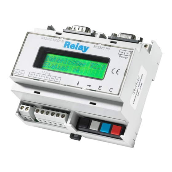
MR005FA+DL / MR006FA+DL 2 Installation and startup Connection plan: RS232C MODEM RS232C PC Power T 1:001 12345678 4076.5 kWh M-Bus RS232 PC: PC interface for service and level converter operation RS232 MODEM: Modem interface for service and level converter operation M-Bus: M+, M- M-Bus terminals (3 pairs). - Page 5 MR005FA+DL / MR006FA+DL RS232 interface: The M-Bus can be accessed by an RS232C interface. A PC should be connected to the right DB9 socket or a modem to the left DB9 plug. Only one of these connectors can be used simultaneously.
- Page 6 Do the actions which are described in “Status: Error” and then press the key again. Please write down the 16 digit string (display config) and send it together with the firmware version no. and serial no. to INFO@RELAY.DE by email. We will send you a working passcode.
-
Page 7: Description Of The Level Converter
MR005FA+DL / MR006FA+DL 3 Description of the Level Converter Function: The RS232C interface signals are directly connected to the M-Bus all the time except during the operation by keyboard, the remote access using the command menu and the automatic readout. External connected controllers (laptop, building control systems etc.) can use the device during the inactivity as a level converter for the physical layer of the M-Bus. - Page 8 MR005FA+DL / MR006FA+DL Planning M-Bus networks: Two effects must be considered before projecting M-Bus networks: 1. The signals must not be distorted to much by the influence of the capacitance of the cable. The capacitance of the network depends on the length of the network, this means the total sum of cable length.
-
Page 9: Description Of The M-Bus Display
MR005FA+DL / MR006FA+DL 4 Description of the M-Bus Display Function The M-Bus Display allows reading the meters using the keyboard and viewing the consumption values on the LCD. The meter reader is then able to get the data of many meters from one central location without the need to enter all the flats and without further technical equipment (laptop). -
Page 10: Keyboard Operation
MR005FA+DL / MR006FA+DL Access by ID: The M-Bus Display supports a different setup of the passcode mode from the menu „Display config. – Passcode mode“. If this mode is activated, the user (tenant) can make a readout limited to his own meter(s). After first key-press the tenant is requested to type in the ID (identification no.) of the required slave. - Page 11 MR005FA+DL / MR006FA+DL Displayed data: The device only displays the most important data for reasons of easy interpretation and not to confuse the reading staff. Some meters offer actual and historical values, different tariffs and additional devices like pulse counters in a heat meter. The first row always shows the primary address and ID for a clear association of the data to the respective meter.
- Page 12 MR005FA+DL / MR006FA+DL Menu structure: Status report: MB Display V1.9 Device ready for work Status: overload: Nominal bus current exceeded max.load: Bus off while over current error: Error occured in data interpretation Passcode B allows access to all functions Passcode A allows access limited to these functions: Passcode request * * The tenant has no access to the menus in the modes "Access via ID"...
- Page 13 MR005FA+DL / MR006FA+DL Page 1 Page 1 ID of location Shows the ID of location (description) Display config. Highest baudr. Highest baudrate for automatic search Lowest baudrate Lowest baudrate for automatic search Search mode Selects search mode: Adr+ID,only Adr, only ID Selects passcode mode: Standard: requests passcode on startup Passcode mode...
- Page 14 MR005FA+DL / MR006FA+DL Description of the most important menus Readout of all: This entry reads all meters according to the list of slaves and displays their data. For each meter its baud rate and primary or secondary address is used for communication. Single readout: The readout of single meters also uses information from the list of slaves.
-
Page 15: Remote Control With Commands
MR005FA+DL / MR006FA+DL 6 Remote control with commands Function In the inactive state the MR00xFA and MR00xDL work like simple level converter. The signals of the RS232C and RS485 interfaces are converted to M-Bus signals and vice versa. The CPU watches the data transmission and reacts on certain control frames. -
Page 16: Pc-Software Fservice
The software FService is described in a separate manual, which is delivered with FService. You will find this free software on the CD "Tools & Docs" and on our homepage www.relay.de. User Manual MR005FA+DL / MR006FA+DL ·04/2018 · VERSION 1.4... -
Page 17: Addendum
MR005FA+DL / MR006FA+DL 9 Addendum 9.1 Error Codes The following table shows the error codes. See “Error fixing – Status: Error”: Code Error No error RAM error (please send the device to us for repair) EEPROM write problem $18, $19, $1C EEPROM read problem Problem with communication to real time clock $30, $31, $32, $33... -
Page 18: Ce Declaration
MR005FA+DL / MR006FA+DL 10 CE Declaration User Manual MR005FA+DL / MR006FA+DL ·04/2018 · VERSION 1.4... - Page 19 MR005FA+DL / MR006FA+DL Notes: User Manual MR005FA+DL / MR006FA+DL ·04/2018 · VERSION 1.4...
Need help?
Do you have a question about the MR005DL and is the answer not in the manual?
Questions and answers