Table of Contents
Advertisement
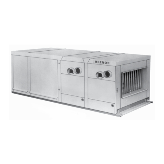
Indoor,
Separated-Combustion
Model SSCBL
WARNING:
!
FIRE OR EXPLOSION HAZARD
Failure to follow safety warnings exactly could result in serious injury, death, or
property damage.
Be sure to read and understand the installation, operation, and service instructions in
this manual.
Improper installation, adjustment, alteration, service, or maintenance can cause
serious injury, death, or property damage.
— Do not store or use gasoline or other flammable vapors and liquids in the vicinity
of this or any other appliance.
— WHAT TO DO IF YOU SMELL GAS
•
Do not try to light any appliance.
•
Do not touch any electrical switch; do not use any phone in your building.
•
Leave the building immediately.
•
Immediately call your gas supplier from a phone remote from the building. Follow
the gas supplier's instructions.
•
If you cannot reach your gas supplier, call the fire department.
— Installation and service must be performed by a qualified installer, service agency,
or the gas supplier.
®
Outdoor, Power Vented
INSTALLATION / OPERATION / MAINTENANCE
Applies to:
CQS
CQS
Model RPBL
Form I-SSCBL/RPBL (Version E.3)
Obsoletes I-SSCBL/RPBL (Version E.2)
Model SSCBL
and Model RPBL
Packaged Systems
Form I-SSCBL/RPBL, P/N 149159 R8, Page 1
Advertisement
Table of Contents

Subscribe to Our Youtube Channel
Related Manuals for Reznor SSCBL Series


Summary of Contents for Reznor SSCBL Series
- Page 1 Form I-SSCBL/RPBL (Version E.3) ® Obsoletes I-SSCBL/RPBL (Version E.2) INSTALLATION / OPERATION / MAINTENANCE Applies to: Model SSCBL and Model RPBL Packaged Systems Indoor, Separated-Combustion Model SSCBL Outdoor, Power Vented Model RPBL WARNING: FIRE OR EXPLOSION HAZARD Failure to follow safety warnings exactly could result in serious injury, death, or property damage.
-
Page 2: Table Of Contents
Table of Contents 1.0 General ...............2 7.2 Supply Voltage and Wiring ........41 7.3 Thermostat and Control Wiring ......42 1.1 Hazard Labels and Notices ........2 1.2 General Installation Information ....... 3 8.0 Controls ..............43 1.3 Warranty ..............3 8.1 Control Locations ............43 1.4 Installation Codes ............3 8.2 Fan Control ...............43 2.0 Furnace Location ............3... -
Page 3: General Installation Information
1.2 General Installation should be done by a qualified agency in accordance with the instructions in this manual and in compliance with all codes and requirements of authorities having Installation jurisdiction. The instructions in this manual apply to Model SSCBL and Model RPBL. Information 1.3 Warranty Refer to the limited warranty form in the "Literature Bag". -
Page 4: Uncrating And Preparation
Reznor distributor. If you are an authorized Distributor, follow the FOB freight policy ® procedures as published by Reznor for Reznor products. ® Check the rating plate for the gas specifications of the furnace and electrical character- istics of the unit to be sure that they are compatible with the gas and electric supplies at the installation site. -
Page 5: Dimensions And Clearances
Other shipped-separate options could include a roof curb, an outside air hood, a gas shutoff valve, a thermostat, an optional control switch, a remote console, a vent exten- sion, a gas supply regulator, and/or a disconnect switch. If ordered with either an evaporative cooling module or a DX or chilled water cooling coil module, the module is shipped separately. - Page 6 4.0 Dimensions 4.1 Dimensions (cont'd) and Clearances 4.1.2 Dimensions of Outdoor Model RPBL (cont'd) FIGURE 3 - Dimensions of Outdoor Model RPBL - inches (mm) Field Wiring 43-17/32 8-15/32 Control Voltage (1106) (215) (19) Optional Furnace Furnace Furnace 100% Blower 40-1/8 31-11/32 18(457)
- Page 7 4.1.3 Dimensions - Optional Cooling Coil Cabinet FIGURE 4 - Optional Cooling 8 (203) 2 (51) 5-1/8 (130) 7/8 (22) 7/8 (22) Coil Cabinets with DX or Chilled Water Coil, with and Liquid Line Side View Connections without Downturn Plenum DX Coil (7/8”...
-
Page 8: Clearances
4.0 Dimensions 4.2 Clearances and Clearances For safety and convenience, provide clearances as shown in the table. Clearance to (cont'd) combustibles is defined as the minimum distance from the heater to a surface or object that is necessary to ensure that a surface temperature of 90°F above the surround- ing ambient temperature is not exceeded. -
Page 9: Mounting Outdoor Model Rpbl
If the rails are not placed directly on a surface, cross-supports should be placed under- neath the rails at the ends of the unit and at all cabinet "joints" (between the blower cabinet and the furnace section, between each furnace section, and between the fur- nace and an optional downturn plenum cabinet). - Page 10 5.0 Suspension 5.4 Mounting Outdoor Model RPBL (cont'd) and Mounting 5.4.3 Mounting Outdoor Models on Field-Supplied Supports (cont'd) (without a roof curb) - Applies to Model RPBL (cont'd) FIGURE 7 - Mounting Support Dimensions With With With Option Standard Option Option AU2 AU 11, 12, 13, Heater(s)
- Page 11 Bottom Duct Connections - The blower section and optional downturn plenum have duct flanges for connection to return air and supply air ducts. Duct opening sizes and curb spacing shown in FIGURE 9D are for currently manufactured curbs that are avail- able from the system manufacturer.
- Page 12 5.0 Suspension 5.4.4 Mounting on a Roof Curb - Model RPBL (cont'd) and Mounting Roof Curb Assembly and Installation Instructions (cont'd) Curbs are shipped unassembled. Field assembly and mounting on the roof are the responsibility of the installer. All required hardware necessary to complete the 5.4 Mounting assembly is supplied.
-
Page 13: Mechanical
6.0 Mechanical WARNING This appliance is equipped for a maximum gas supply pressure of 1/2 6.1 Gas Piping and psi, 3.5 kPa, or 14 inches water column. NOTE: Supply pressures higher Pressures than 1/2 psi require installation of an additional service regulator exter- nal to the unit. - Page 14 6.0 Mechanical Sizing Gas Supply Lines (cont'd) Capacity of Piping - Cubic Feet per Hour based on 0.3" w.c. Pressure Drop Specific Gravity for Natural Gas -- 0.6 (Natural Gas -- 1000 BTU/Cubic Ft) Specific Gravity for Propane Gas -- 1.6 (Propane Gas -- 2550 BTU/Cubic Ft) 6.1 Gas Piping Diameter of Pipe Length...
-
Page 15: Venting And Combustion Air
6.2 Venting and 6.2.1 Separated-Combustion Model SSCBL Combustion Air Each furnace section in the packaged system MUST BE equipped with both combus- tion air and exhaust piping to the outdoors. Refer to FIGURES 2 and 3 in Paragraph 4.1 for locations of vent and inlet air collars. The vent pipe collar is 6" O.D.; the inlet air collar is 6"... - Page 16 6.0 Mechanical 4) Pipe Diameter and Length (cont'd) (cont'd) Maximum Pipe Length from EACH Furnace Section to a Unique 6.2 Venting and Concentric Adapter Box -- Minimum length is five feet (1.5M). Combustion Air Pipe Diameter Equivalent Length for an Elbow Model Maximum (cont'd)
- Page 17 FIGURE 12 - Follow STEPS to join the Double-Wall (Type B) Pipe to the Taper-type Reducer that Joins it to the Single-Wall or Category III Vent Run Make this connection a maximum of 6" (152mm) from the concentric adapter box. Figure 12 - STEP 1 Figure 12 - STEP 2 Figure 12 - STEP 3...
- Page 18 6.0 Mechanical 6.2.1.1 Specific Venting Requirements (cont'd) (read all before installing) (cont'd) Pipe Connections at the Concentric Adapter Box 6.2 Venting and When pipe diameters differ, depending on direction of airflow, join the pipes with either Combustion Air a taper-type reducer or enlarger. Refer to illustrations in FIGURE 14 for pipe connec- (cont'd) tion requirements at the concentric adapter box.
- Page 19 6.2.1.2 Horizontal Vent Components Required - Factory and Field Instructions - Model Description SSCBL 205883 Complete Horizontal Vent Kit (Same as Option CC6) 205885 Concentric Adapter Box Assembly (See FIGURE 13, page 17.) 53316 Screened Exhaust Assembly (illustrated below) FIGURE 15 - Parts in 205894 Inlet Guard (illustrated below) each Horizontal Vent 37661 #10-16 x 1/2"...
- Page 20 6.0 Mechanical (cont'd) 6.2.1.2 Horizontal Vent Instructions - Model SSCBL (cont'd) 3. Prepare a hole through the outside wall for the 8" (203mm) diameter combustion air pipe. Outside wall construction thickness should be between 1" 6.2 Venting and (25mm) minimum and 48" (1143mm) maximum. The larger diameter combustion air Combustion Air pipe serves as clearance for the vent pipe on non-combustible construction.
- Page 21 FIGURE 17 - Installation of a Typical Separated-Combustion Unit with Horizontal Vent and Combustion Air Pipes (Option CC6) One piece of 2” (51mm) 2” (51mm) if wall is combustible Double-Wall Attach box to wall with brackets. Vent Pipe Inlet Air Guard Combustion Air to heater (seal joints) Screened...
- Page 22 6.0 Mechanical 6.2.1 Separated-Combustion Model SSCBL (cont'd) (cont'd) 6.2.1.3 Vertical Vent Instructions - Model SSCBL 6.2 Venting and Description Combustion Air 205896 Complete Vertical Vent Kit (Same as Option CC2) (cont'd) 205885 Concentric Adapter Box Assembly (See FIGURE 13, page 17.) 53326 Exhaust (Vent) Terminal (illustrated below) Components Required 53330 Combustion Air (illustrated below)
- Page 23 FIGURE 20 - Brackets 2) Attach the Box to the Roof (Step 5) for Attaching the When the box is attached to the roof in Step 5, use the Concentric Adapter Box 2-1/2” (64mm) portion of the brackets. To adjust to construction each bracket has three 7/32”...
- Page 24 6.0 Mechanical Determine the minimum length by adding the requirements. Starting at the bottom, the maximum the vent pipe can extend below the box is 6” (152mm); plus 6” (cont'd) (152mm) through the box; plus length of bracket extending above the box; plus the width of the roof;...
- Page 25 FIGURE 24 - Installation of Unit with Vertical Vent Terminal/Combustion Air Inlet (Option CC2) Vent (flue exhaust) Terminal 9-3/8” (238mm) Side View Rear 12” (305mm) minimum Double-wall Vent View (flue exhaust) Pipe Cold Climate NOTE: In geographic areas where the design ambient is 6 ft (1.8M) minimum -10°F or lower, this Seal with silicone...
-
Page 26: Unit Inlet Air
6.0 Mechanical 6.2 Venting and Combustion Air (cont'd) (cont'd) 6.2.2 Venting Outdoor Power Vented Model RPBL (cont'd) Optional vertical vent piping provides compliance with local codes that require either 10-ft (3M) horizontal or 4-ft (1.2M) vertical clearance between the flue outlet and fresh air intake of the heating system and/or the building. - Page 27 hood top panel must be between the blower cabinet top and the end panel. Reinsert all of the sheetmetal screws. 2. Side Panels -- Slide the air hood right side panel into the groove in the blower cabinet end panel. Be sure that the side panel is underneath and to the inside of the air hood top panel.
- Page 28 6.0 Mechanical 6.3.3 Optional Dampers and Controls - RPBL and SSCBL (cont'd) Damper controls are identified on the wiring diagram as AR Options. The illustration in FIGURE 30A is intended to show location only of various air con- 6.3 Unit Inlet Air trol accessories and does not represent suggested combinations of accessories.
- Page 29 It maintains a selected positive or negative pressure setpoint by changing the amount of outside air being introduced to the building through the modulating outside air damp- ers. As more pressure is required in the building, the pressure null switch activates the damper motor driving the outside air damper towards the full open position and the recirculated air damper towards the closed position.
- Page 30 6.0 Mechanical 6.3 Unit Inlet Air (cont'd) (cont'd) 6.3.4 Optional Filter Rack & Filters (cont'd) Type of Filter *Average Efficiency *Average Arrestance Filter Airflow Range Disposable 2" Less than 20% Disposable ....0 to 400 FPM Permanent 2" Less than 20% 64% to 67% FIGURE 32 - Filter Pleated Disposable..0 to 500 FPM...
- Page 31 Optional Dirty Filter The optional dirty filter pressure switch is used to provide warning to the user by ener- Switch gizing an indicator light on an optional remote console. The light indicates that the filters are in need of cleaning or changing. The adjustable, single-pole/normally open differential switch closes when an increase in pressure differential above the setpoint, is sensed across the filter bank.
- Page 32 6.0 Mechanical Make certain the surface is level and free of debris where cooling module will be mounted. (cont'd) Provide a weather-resistant, solid wood or metal base under legs of cooling 6.3 Unit Inlet Air module base. (cont'd) FIGURE 35 - Field-Assembled Base for Optional Evaporative Cooling Module 6.3.5 Optional...
- Page 33 FIGURE 36 - Removal and Replacement of Evaporative Cooling Module Media 45° FIGURE 37 - Media must be Screen installed with 45° angle sloping downward toward the incoming Retainer outside air. Screw IMPORTANT: The media is made up of two different sheets of cooling material.
- Page 34 6.3.5 Optional Evaporative Cooling Module - RPBL (cont'd) 6.0 Mechanical (cont'd) Using a mild soap solution, wash all deposits from the inside of the pump and remove all debris from the impeller. 6.3 Unit Inlet Air 6. Reassemble the pump. Replace the parts in exact reverse order, being careful that (cont'd) everything is returned to its proper position.
- Page 35 Instructions for Lifting 1. After the blower/furnace packaged system is in place on the roof curb or mounting rails, use a 9/16" wrench or socket to remove the lifting lugs that are on the and Attaching Cabinet discharge end of the system. (NOTE: If suspending 2.
- Page 36 Instructions for Lifting and Attaching Coil Cabinet (cont'd) FIGURE 40D - Position 3) Refer to FIGURE 40E. On the leg of the downturn plenum next to the cooling the remaining side coil cabinet locate the mounting screw illustrated. Measure up 6" (152mm). At connector over the same centerline as the screw, drill the first 7/8"...
- Page 37 6.3.6 Optional Cooling c) Run the wires attached to the damper motor 1) out through the hole in the Coil Cabinet, Option discharge plenum leg into the cooling coil cabinet, 2) through the blockoff plate, across the coil cabinet, 3) out through the hole in the cooling coil cabinet leg, and AU (cont'd) 4) into the furnace section.
-
Page 38: Duct Connections - Sscbl And Rpbl
6.0 Mechanical FIGURE 40K - Top Filler Panel Installed (cont'd) Before the top filler 6.3 Unit Inlet Air panel is attached, (cont'd) remove the backing and adhere the gasket strip 6.3.6 Optional Cooling along the bottom of the Coil Cabinet, Option outside edge so that AU (cont'd) any gaps between the... -
Page 39: Blowers, Belts, And Drives
• Removable Panels (See FIGURE 42.). - The ducts should have removable access panels. These openings must be accessible when the furnace is in service and should be a minimum of 6" x 10" (152mm x 254mm) in size so smoke or reflected light may be observed inside the casing to indicate the presence of leaks in the heat exchanger. - Page 40 6.0 Mechanical 7. Turn on the electric and the gas. Light the heater following the instructions on the lighting instruction plate. (cont'd) 8. Check the motor amps with an amp meter. The maximum motor amp rating on the 6.5 Blowers, Belts, motor nameplate must not be exceeded.
-
Page 41: Electrical Supply And Controls
If the system is equipped with an optional variable frequency drive, the motor will oper- Optional Variable ate on speeds as determined by the electrical frequency. 60 hertz is maximum speed. Frequency Drive Speeds must be within the temperature rise range approved for a Model SCE Series 6 heater which is 30-90°F. -
Page 42: Thermostat And Control Wiring
7.0 Electrical Disconnect Switch A disconnect switch is a required part of this installation. The disconnect switch may be Supply and fusible or non-fusible. When providing or replacing fuses in a fusible disconnect switch, Controls use dual element time delay fuses and size according to 1.25 times the maximum total (cont'd) input amps. -
Page 43: Controls
8.0 Controls 8.1 Control Locations FIGURE 46 - 41 1 27 30 31 32 33 34 35 36 37 38 39 40 Locations of Standard and Optional Controls NOTE: Illustration of cabinet is not entirely accurate Optional Downturn Plenum Cabinet for these models. -
Page 44: High Temperature Limits
8.0 Controls 8.3 High Temperature Limits Each furnace is equipped with a non-adjustable high temperature limit switch which (cont'd) shuts off the gas in the event of motor failure, lack of air due to dirty filters, or restric- tions at the inlet or outlet of the unit. See Paragraph 9.3, "Check Installation after Start- up", for checking operation of high temperature limit controls. - Page 45 All furnaces are standardly equipped with a 24-volt combination valve which includes the automatic electric on-off valve controlled by the room thermostat, the pressure regulator, the safety pilot valve, and the manual shutoff valve. The standard gas valve allows for single-stage control from a single-stage, 24-volt thermostat. The standard combination control valve is replaced with a two-stage combination gas 8.8.2 Optional Two- control valve providing for low fire or high fire operation controlled by a two-stage...
- Page 46 8.0 Controls 8.8 Gas Controls (cont'd) (cont'd) 8.8.3 Optional Two-Stage Operation - Makeup Air (cont'd) TABLE B - Recommended Settings for Staging Application - Options AG4, AG5, AG17, and AG19 Ductstat Settings - Set each Ductstat (See FIGURE 47) in furnace "order" No.
- Page 47 FIGURE 49 - Duct Temperature Sheetmetal Sensor Location Retaining Plate 1. Remove access panel in the ductwork Gasket adjacent to the control compartment access panel. Sensor Capillary 2. Element is retained by either spring Sensor Bracket clips or cable straps. (NOTE: Bracket 3.
- Page 48 8.0 Controls Electronic Modulation between 25% and 100% Firing Rate), Options AG39, AG40, AG41, AG42 (cont'd) (cont'd) The furnace with this type of electronic modulation will ignite at any input rate in the available range and will maintain average thermal efficiencies equal to or greater than 8.8 Gas Controls the thermal efficiency at full fire.
- Page 49 Sensor Location - For the convenience of the installer, the duct temperature sensor is factory installed in the cabinet leg (See FIGURE 49, page 47). Although the sensor has a mixing tube, Options AG39 and at this distance from the discharge it does not receive a true mix, so the temperature AG41 read by the sensor will be slightly higher than the actual air entering the ductwork.
- Page 50 8.0 Controls Electronic Modulation between 25% and 100% Firing Rate), Options AG39, AG40, AG41, AG42 (cont'd) (cont'd) Wiring and Service 8.8 Gas Controls For wiring, consult the wiring diagram attached to the furnace. All wires in the electrical (cont'd) box connecting the modulation controls must be 150°C. 8.8.4 Optional This is a unique system which includes custom-built components and custom settings.
-
Page 51: Pilot And Ignition Systems
8.9 Pilot and Ignition System - Natural gas units are equipped with a spark ignited intermittent safety pilot system that shuts off the pilot gas flow between heat cycles. Propane units Ignition (or as an option on natural gas units) require a lockout device that stops the gas flow to Systems the pilot if the pilot fails to light in 120 seconds. -
Page 52: Burner Air Shutters
8.0 Controls All propane gas burners are equipped with one flash carryover and a regulated gas lighter tube system. The carryover lighter tube receives its gas supply through a regula- (cont'd) tor, simultaneously with the gas to the burner orifices. 8.10 Burners, During regular service, check the main burner ports, the carryover assemblies, and the Orifices, and... -
Page 53: Start-Up
9.2 Start-Up Close all panels tightly. Turn electric and gas supply on to the furnace. Adjust the thermostat or ductstat so that a call for heat exists. Observe for complete sequencing of safety pilot and ignition. Operating Sequence c) If the flame is extinguished during main burner operation, the safety switch closes the main valve 1. -
Page 54: Maintenance And Service
10.0 Maintenance WARNING and Service If you turn off the power supply, turn off the gas. See Hazard Levels, page 2. This unit will operate with a minimum of maintenance. To ensure long life and satis- factory performance, a furnace that is operating under normal conditions should be inspected every four months. - Page 55 equilibrium, close the manual shutoff valve. Observe the gas pressure. There should be no loss of gas pressure on the manometer. If the manometer indicates a loss of pressure, replace the combination gas valve before placing the heater in operation. NOTE: Operational pressure settings and instructions for checking pressure settings are in Paragraph 6.2.
- Page 56 10.0 Maintenance 10.2.2 Pilot and Main Burners (cont'd) and Service Pilot and Spark Ignition System (cont'd) (cont'd) If no spark occurs, check the following: a) Voltage between Terminals TH and 7 on the ignition controller should be at least 10.2 Maintenance 20 volts and no higher than 32 volts.
-
Page 57: Troubleshooting
10.3 Troubleshooting TROUBLE PROBABLE CAUSE REMEDY Venter motor 1. No power to the furnace. 1. Turn on power, check supply fuses or circuit breaker. will not start 2. No 24-volt power to venter relay. 2. Turn up thermostat, check control transformer output. Check for loose or improper wire connections. - Page 58 Form I-SSCBL/RPBL, P/N 149159 R8, Page 58...
-
Page 59: Index
INDEX Dimensions 5 Vertical Vent Kit 22 Components 4 Mounting Support Dimensions Installation of Model SSCBL Spark Gap 56 Optional Airflow Proving with Vertical Vent 25 Stage-Adder Module 46 Switch 44 Roof Curb Dimensions 11 INSTALLATION RECORD 60 Stage Adder Module 4 Ampere Rating 42 Dimensions - Concentric Installer 60... -
Page 60: Installation Record - To Be Completed By The Installer
________________________________________________________________________________________ BUILDING OWNER OR MAINTENANCE PERSONNEL: For service or repair • Contact the installer listed above. • If you need additional assistance, contact the Reznor Distributor listed above. ® • For more information, contact your Reznor Representative by calling 800-695-1901.
Need help?
Do you have a question about the SSCBL Series and is the answer not in the manual?
Questions and answers