Table of Contents
Advertisement
Quick Links
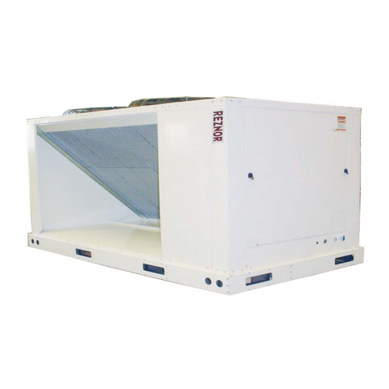
Air Cooled Condensing Unit
Designed for Reznor Split Systems
Check, Test, and Startup MUST be followed, as documented in this manual.
A completed Condenser Startup Form (page 41) may be required for validation of any warranty
claims. The factory reserves the right to deny warranty without completed Condenser Startup Form.
This booklet includes operation, maintenance, and service information. Before beginning any procedure, carefully
review the information, paying particular attention to the warnings. All installation procedures including handling of
refrigerant must be in compliance with all codes and requirements of authorities having jurisdiction.
Condenser Startup Form on page 48 should be completed on initial startup.
®
IMPORTANT:
Installer should complete information on page 49.
Owner should keep this booklet for future reference.
Installation/Operation/Maintenance
Applies to: Model MASA
R-410A
Refrigerant
Only
0901MASA--EN, page 1
Advertisement
Table of Contents

Related Manuals for Reznor MASA


Summary of Contents for Reznor MASA
- Page 1 Installation/Operation/Maintenance ® Applies to: Model MASA Air Cooled Condensing Unit Designed for Reznor Split Systems R-410A Refrigerant Only IMPORTANT: Check, Test, and Startup MUST be followed, as documented in this manual. A completed Condenser Startup Form (page 41) may be required for validation of any warranty claims.
-
Page 2: Table Of Contents
6.1.3.5 Brazing Connections ... . . 16 Model MASA Technical Information... .41 6.1.3.6 Piping Support and Insulation ..16 Performance tables . -
Page 3: General
1.0 GENERAL 1.1 Hazard Labels There are warning labels on the condensing unit and throughout this manual. For your safety, read the definitions below and comply with all boxes labeled and Notices CAUTION, WARNING, and DANGER during installation, operation, mainte- nance, and service of this system. -
Page 4: General Information
A Model MASA outdoor condensing unit operates on R-410A refrigerant and has two independent refrigeration circuits configured in an approximate 1/3- 2/3 arrangement. The Model MASA condensing unit is designed for use with a Reznor PREEVA air handler unit with a 1/3-2/3 two-circuit cooling coil. PREEVA indoor Model is SDH;... -
Page 5: Receiving, Moving, And Uncrating
3.0 RECEIVING MOVING/UNCRATING 3.1 Receiving The unit was test operated and inspected at the factory prior to crating and was in proper operating condition. If the heater has incurred damage in shipment, document the damage with the transport company and contact your supplier. 3.2 Moving The heavy gauge base of the condensing unit has forklift openings in both sides. -
Page 6: Dimensions
4.2 Dimensions Figure 2a - model MASA 15 and 22 dimensions Figure 2b - model MASA 30, 37, 44, 59 dimensions MASA Sizes Dimensions (mm) 30, 37 2184 2134 44, 59 2794 2743 0901MASA--EN, page 6... -
Page 7: Mounting
Table 1 Approximate Operating Weight of Condensing Unit MASA Size The heavy gauge base of the condensing unit has fork lift holes and a pair of 5.2 Lifting lifting holes on each corner for rigging. If lifting with a forklift, forks must have a minimum length of 610mm. -
Page 8: Location Of Piping Connections At The Split System Evaporator Coil
Refer to FIGURE 4A or 4B for illustration of a split system refrigerant piping system con- necting a MASA condensing unit to a PREEVA evaporator coil. In FIGURE 4A, the con- densing unit is higher than the evaporator coil. In FIGURE 4B, the condensing unit is lower than the evaporator coil. - Page 9 Figure 4A - Refrigerant Piping on a PREEVA Split System with the Condensing Unit Installed at a Higher Level than the Air Handler Unit 7. Field installation P or oil trap at the end of the evaporator 0901MASA--EN, page 9...
- Page 10 Figure 4B - Refrigerant Piping on a PREEVA Split System with the Condensing Unit Installed at a Lower Level than the Air Handler Unit 0901MASA--EN, page 10...
-
Page 11: Refrigerant Piping Guidelines (R-410A Refrigerant)
6.1.3 Refrigerant Piping Guidelines (R-410A Refrigerant) The information in this section is a guideline and is not intended to provide all of the instructions needed for designing and installing the R-410A refrigerant lines. The installer is responsible for designing the refrigerant connecting sys- tem and for complying with standard refrigerant piping procedures. - Page 12 IF AN APPLICATION REQUIRES MORE THAN 18.3M OF EQUIVALENT LENGTH OF TUBING (LIQUID LINE OR SUCTION LINE) BETWEEN THE CONDENSER AND THE AIR HANDLER, CONTACT REZNOR FOR APPROVAL. Table 3 - Recommended Size of Refrigerant Piping for each Segment...
-
Page 13: Liquid Line Piping
Length IMPORTANT Note: Recommended maximum total equivalent line length between the condenser and evaporator coil is 18.3. For line segments longer than 18.3m equivalent length, consult Reznor for approval. 6.1.3.3 Liquid Line Piping Design the liquid lines (a line for each circuit from the condenser to the thermal expan-... - Page 14 Protect the filter drier from excessive heat when brazing. Table 4 - Two Liquid Line Refrigerant R410A Liquid Line Filter Driers Shipped in the Condensing Unit MASA Filter Driers are Shipped Circuit for Field Installation Loose in the Condensing...
-
Page 15: Suction Line Piping
• Never place bulb in a trap or downstream of a trap. • Position bulb as shown in FIGURE 5. • Bulb must have 100% contact with tubing. • Secure the bulb tightly. • Cover bulb with waterproof insulation. Figure 5 - Position of the Position bulb flat against the surface of the suction line tubing. -
Page 16: Brazing Connections
6.1.3.5 Brazing Connections CAUTION Do not leave system open to the atmosphere any longer than minimum required for installation. Exposure for more than five minutes may contaminate the system. POE oil in the compressors is extremely susceptible to moisture absorption. Always keep ends of tubing sealed during installation. -
Page 17: Leak Test The Refrigerant Circuits
The MASA condensor unit was pressure tested in the fac- installed piping by closing tory. It is forbidden to redo a pressure test on the MASA unit as severe damage the shut-off valves (2 per wlll occur. -
Page 18: R-410A Refrigerant Charge
Charge the refrigerant slowly through the gauge port on the liquid line. R-410A refrigerant must be charged as a liquid. Provide in the field installed liquid line a charge point. That charge point is also neces- sary for pressure testing (see 6.2.3). MASA Size Circuit Table 6 Condenser Refrigerant Charge by... -
Page 19: Electrical And Wiring
7.0 ELECTRICAL The electrical installation may only be carried out by an appropriately & WIRING qualified person current to IEE regulations. The supply line to the air cooled condensing unit should include a main switch. The minimum distance 7.1 General between the contacts must be more than 3mm. - Page 20 Compressor Wiring - A 3-phase scroll compressor must be phased correctly or com- pressor will operate in reverse. Since there is a chance of unknowingly connecting the power in such a way as to cause rotation in reverse, it is important to check this on startup.
- Page 21 Figure 6a - Wiring Diagram MASA 15, 22 0901MASA--EN, page 21...
- Page 22 Figure 6b - Wiring Diagram MASA 30, 44 0901MASA--EN, page 22...
- Page 23 Figure 6c - Wiring Diagram MASA 59 0901MASA--EN, page 23...
-
Page 24: Controls And Operation
OPERATIONS An FX07 platform was programmed to work properly with a PREEVA (SDH or RDH) and a MASA appliance and can be supplied as option. An anti-short 8.1 Digital control cycling protection for the compressors is integrated in the FX07. When... -
Page 25: Final Checks And Start-Up
Assumptions: All connections are made; actual startup is imminent. Site 9.0 FINAL CHECKS & is clean; all excess supplies, scraps, and debris have been removed. START-UP WARNING: 9.1 General Comments To prevent injury or death due to electrocution or contact with moving parts, lock disconnect switch open when doing checks prior to startup. -
Page 26: Start-Up
9.2 Start-up CAUTION Note: Redo startup Crankcase heaters must be allowed to warm up for at least 24 hours procedures when prior to startup. Disable cooling controls before turning on power the cooling season to warmup crankcase heaters. See Hazard Levels, page 3. begins. -
Page 27: Operating Sequence
9.2.2 Operating Sequence MPORTANT • All refrigeration For a three-stage cooling sequence, the operating sequence is #1 (Circuit A Compressor); then #2 (Circuit B Compressor); and then #1 checks MUST be and #2 (both Circuit A and Circuit B Compressors). made by a refrig- eration technician 9.2.3 Refrigerant Charge... -
Page 28: Determine Superheat
9.2.3.2 Determine SUPERHEAT Measure and record temperature (insulate probe from surrounding air tem- perature) and pressure in the suction line at the compressor inlet. STEP 1) Record Measurements: Temperature = _______°C and Pressure = _______ barg STEP 2) From Temperature/Pressure Conversion Chart, APPENDIX, page 40, convert Measured Pressure (STEP 1) to ________°C STEP 3) Subtract Measured Temperature (STEP 1) from... -
Page 29: Maintenance And Service
The procedures in the schedule below are only for the condensing unit. Refer to and comply with the maintenance schedule for the Reznor PREEVA unit or other air handler with evaporator. 10.2 Maintenance... -
Page 30: Condenser Fan(S) Maintenance
10.3 Condenser Check condenser fans. Carefully clean debris and dirt from guards, fan blades Fan(s) and motors. If any parts need to be replaced, use only factory-authorized replace- Maintenance ment parts. Figure 8 - Condenser Fan Rotation and Fan Fan rotation is Blade Spacing from Top Top View counterclockwise. -
Page 31: Compressor Maintenance And Replacement
Use the fol- lowing 13 steps as a checklist, taking each item in order before proceeding to the next. If more information is required, contact your Reznor supplier. 0901MASA--EN, page 31... - Page 32 All components of the manufacturer’s Model No. must be identi- cal. System components are matched to the compressor. Replacing a com- pressor with a model other than the Thomas & Betts (Reznor) specified replacement will void the product warranty.
- Page 33 CAUTION DO NOT LIFT compressor by copper tubing; damage will occur. Compressor must remain upright. See Hazard Levels, page 3. WARNING Wear eye protection, gloves, and protective clothing when handling refrigerant, POE oil, and when brazing. See Hazard Levels, page a) BEFORE REMOVING THE FAULTY COMPRESSOR, remove R-410A refrigerant charge using proper recovery procedures.
- Page 34 Use an acid test kit to check the oil for acid. If acid is found, beginning in Step 4, follow procedures indicated for burnout cleanup. Dispose of oil and compressor using an approved environmentally safe disposal method. Table 8 - Compressor Oil Charge MASA Size Circuit Compressor ZP20K ZP39K ZP29K...
- Page 35 □ Step 6. Check Circuit for Leaks Comply with instructions in Paragraph 6.2.1. □ Step 7. Evacuate the Circuit Comply with instructions in Paragraph 6.3. Continue and/or repeat Steps 6 and 7 until evacuation is complete. CAUTION Do not use the replacement compressor as an evacuation assist and never apply voltage to a compressor while it is in a vacuum.
- Page 36 □ Step 10 . System Startup Connect refrigerant pressure gauges and electric meters. Refer to Start-Up Paragraph 9.2 and perform all procedures required prior to checking sub- cooling and superheat which is done in Step 11. CAUTION Be sure to connect pressure gauges to the suction and discharge lines before start-up so that compressor rotation can be checked immediately.
-
Page 37: Troubleshooting Chart
IMPORTANT: 10.6 Troubleshooting Do not release refrigerant to the atmosphere! If required service Chart procedures include the adding or removing of refrigerant, the service technician must comply with all national, state or province, and local laws. SYMPTOM POSSIBLE CAUSE REMEDY A. - Page 38 SYMPTOM (cont’d) POSSIBLE CAUSE (cont’d) REMEDY (cont’d) F. High suction pressure 1. Excessive load on evaporator coil. 1. Check for high entering wet bulb temperature. Check for excessive air. 2. Compressor is unloaded. 2. Check head pressure; check thermal expansion valve if not functioning properly;...
-
Page 39: Spare Parts
10.7 Spare parts list 0901MASA--EN, page 39... -
Page 40: Appendix
Cut filter drier out with a tubing cutter. • Model MASA R-410A compressors require Ultra 22CC POE oil. • POE oil absorbs moisture quickly; do not expose oil to the atmosphere. -
Page 41: Model Masa Technical Information
APPENDIX (cont’d) Model MASA Technical Information General 0901MASA--EN, page 41... -
Page 42: Performance Tables
APPENDIX (cont’d) Performance tables 0901MASA--EN, page 42... - Page 43 APPENDIX (cont’d) 0901MASA--EN, page 43...
- Page 44 APPENDIX (cont’d) 0901MASA--EN, page 44...
- Page 45 APPENDIX (cont’d) 0901MASA--EN, page 45...
- Page 46 APPENDIX (cont’d) 0901MASA--EN, page 46...
- Page 47 APPENDIX (cont’d) 0901MASA--EN, page 47...
-
Page 48: Pressure/Temperature Chart For R-410A Refrigerant For Checking Subcooling And Superheat
APPENDIX (cont’d) Pressure/ R-410A Refrigerant R-410A Refrigerant Temperature temperature pressure temperature pressure Chart for R- °C bar (abs) °C bar (abs) 410A Refrigerant -20,0 25,0 16,4 for Checking -19,0 26,0 16,9 Subcooling and -18,0 27,0 17,3 Superheat -17,0 28,0 17,8 -16,0 29,0 18,2... -
Page 49: Condenser Startup Form
® CONDENSER STARTUP FORM Complete on initial startup. Completed form may be required for warranty. Date: __________ Customer Name: _______________________________ Condenser Model #: _______________________ Address: _____________________________________ Condenser Serial #: _______________________ City: ________________________________ Air Handler Brand: ________________________ Contractor Firm Name: __________________________ Air Handler Model #: _______________________ Installing Contractor: ____________________________ Air Handler Serial #: _______________________ PRE-STARTUP CHECK LIST ( See Section References for details.) -
Page 50: Form
________________________________________________________________________________________ BUILDING OWNER OR MAINTENANCE PERSONNEL: For service or repair • Contact the installer listed above. • If you need additional assistance, contact the Reznor Distributor listed above. Manufacturer Distributor ReznorEurope N.V. Reznor U.K. Limited J&M Sabbestraat 130 Park Farm Road...
Need help?
Do you have a question about the MASA and is the answer not in the manual?
Questions and answers