Advertisement
The AMD-102 wireless magnetic contact is designed for operation as part of the ABAX two-
way wireless system. The device is supported by the ACU-100 controller with firmware
version 2.01 or later and by the INTEGRA 128-WRL control panel with firmware version 1.07
or later. This manual applies to the magnetic contact with electronics version 1.3 or later.
Two reed switches are employed in the magnetic contact. You can
program by radio which of them is to be active. The magnetic
contact has two additional inputs (one NC type and the other one
for roller shutter detector). It occupies two positions in the ABAX
system (first: magnetic contact; second: additional inputs).
Explanations for Fig. 1:
1 - additional input terminals:
R
- input for roller shutter detector
COM - common ground
M
- NC type input
2 - tamper contact which reacts to opening and/or tearing off the
housing from its mounting surface.
3 - CR123A 3 V lithium battery, ensuring operation for approx.
3-year period. The device monitors the battery status. When the
voltage drops to 2.6 V, a low battery message is sent. Indication
of the low battery status will continue until the battery is
replaced.
4 - location of the side reed switch (mounted on the other side of
the electronics board).
5 - location of the bottom reed switch (mounted on the other side
of the electronics board).
The LED indicator is only "on" in the test mode, indicating
communication (during polling), violation and tamper.
1. Installation
Before you mount the magnetic contact permanently, check the level of signal
received from the device by the ACU-100 controller or by the INTEGRA 128-WRL
control panel and, if necessary, change the place of installation so that the
location is optimal in terms of communication.
Install the battery inside the magnetic contact just before registering it in the
ABAX system. If unregistered or having no communication with the ABAX
system, the device will consume more energy, which will reduce the battery life.
Be particularly careful during installation so as not to make damage to the reed
switches on the electronics board.
The magnetic contact is designed for indoor installation. The detector should be mounted on
a fixed surface (e.g. window or door frame), and the magnet on a movable surface (e.g.
window or door). Mounting the magnetic contact on ferromagnetic surfaces and/or near to
WIRELESS MAGNETIC CONTACT WITH INPUT
FOR ROLLER SHUTTER DETECTOR
®
AMD-102
amd102_en 11/12
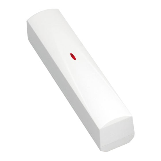
Fig. 1. View of detector
electronics board.
Advertisement
Table of Contents

Related Manuals for Satel AMD-102


Summary of Contents for Satel AMD-102
- Page 1 AMD-102 amd102_en 11/12 The AMD-102 wireless magnetic contact is designed for operation as part of the ABAX two- way wireless system. The device is supported by the ACU-100 controller with firmware version 2.01 or later and by the INTEGRA 128-WRL control panel with firmware version 1.07 or later.
- Page 2 AMD-102 SATEL strong magnetic and electrical fields is not advisable, because it can result in malfunctioning of the device. 1. Open the housing. 2. Install the battery and add the magnetic contact to the wireless system (see the ACU-100 controller user manual, INTEGRA 128-WRL control panel installer manual or VERSA control panel installer manual).
-
Page 3: Specifications
SATEL AMD-102 9. Configure the magnetic contact: – for the magnetic detector, define which of the two reed switches is to be active; – for the input for roller shutter detector, program the pulse count (the number of pulses after which the input will be violated) and pulse validity duration (the time counted from the pulse occurrence, during which next pulses must occur for the input to become violated). - Page 4 Manufacturer: SATEL spółka z o.o. ul. Schuberta 79 Product: 80-172 Gdańsk, POLSKA AMD-102 – Wireless magnetic contact tel. (+48) 58 320-94-00 fax. (+48) 58 320-94-01 Product description: Magnetic contact intended for use with ABAX wireless alarm system components with additional analyzed input for connecting external roller shutter detector, operating at 868MHz.
Need help?
Do you have a question about the AMD-102 and is the answer not in the manual?
Questions and answers