Denon AVR-3313CI Manual
Integrated network av receiver
Hide thumbs
Also See for AVR-3313CI:
- User manual ,
- Owner's manual (187 pages) ,
- Getting started manual (11 pages)
Table of Contents
Advertisement
Model Information
Index
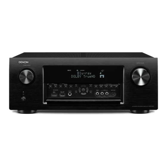
Front Panel
Rear Panel
Remote Control
Warranty
Reset Procedure
Accessories
Protection History
Display Mode
Upgrades/Updates
Product Specifications
I/R Codes
NOTE:
This edition is missing the FAQ's content (pages 15 and 16) .................................................................7/30/2015
This edition is missing the link to the IR Codes.....................................................................................7/30/2015
MODEL:
Model Information
INTEGRATED NETWORK AV RECEIVER
AVR-3313CI
1
MI073015E3-1
Advertisement
Table of Contents


Need help?
Do you have a question about the AVR-3313CI and is the answer not in the manual?
Questions and answers